Control
Center
|
|
Control Center
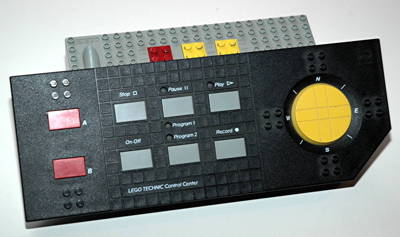
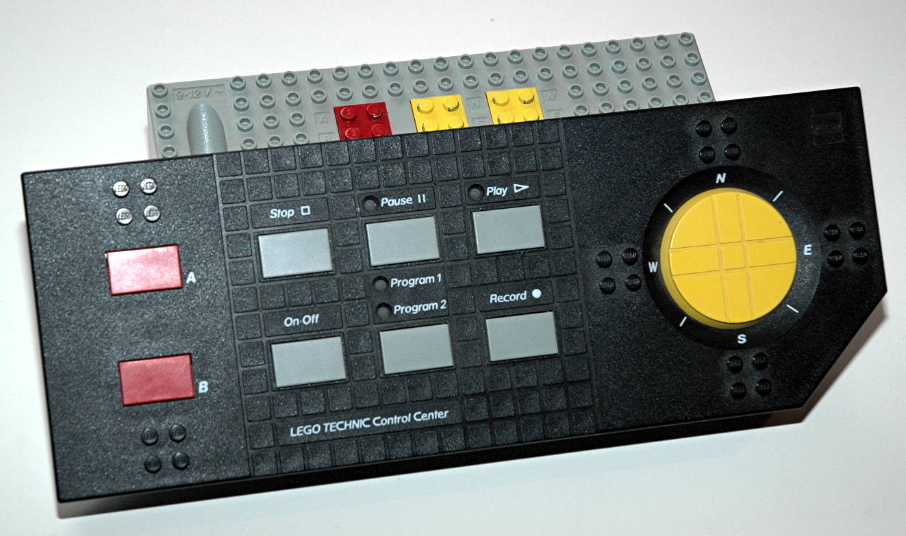
The Control Center is the heart of this set. It was the first
programmable power system for LEGO® motors. There
is a battery compartment on the bottom which holds 6 C sized
batteries (LR14) in series, producing a total of 9 volts DC. This
particular unit is nearly identical to that found in 8094 except that
the buttons are a different color and it has an input for a
transformer! This allows it to be powered from a wall plug
instead of using up dozens of batteries.
The Control Center has 3 color coded power outputs, each capable of
driving a 9V motor. The red output is labeled "A-B" and is
controlled by the two red buttons on the left with the same
labels. One buttons drives one direction, and the other reverses
polarity and drives the motor the other way. The yellow
outputs are labeled "N-S" and "E-W". They are controlled by a 4
way control pad on the right. Movement of the control pad in a
diagonal direction effectively controls 2 channels at once.
The gray buttons in the center control programming. There are two
memory sections which the Control Center can toggle between. Once
a memory is selected, you can push Program and the system will record
your inputs, including duration, and including pauses. When you
are done recording the program, you push Stop and it is stored to
memory, even if the unit is switched off. You can then play it
back (Go) at any time, or you can control the system manually.
There is obviously some limit to the amount of memory on the system so
it can only record a certain number of inputs, however, I have never
found the limit.
|
|
1st
Model: Helicopter
|
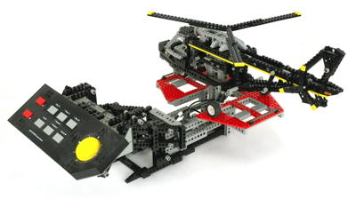
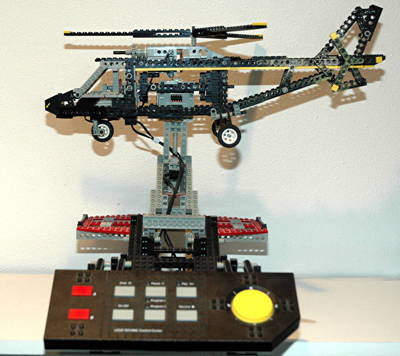
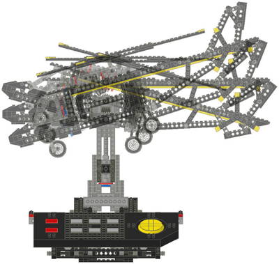
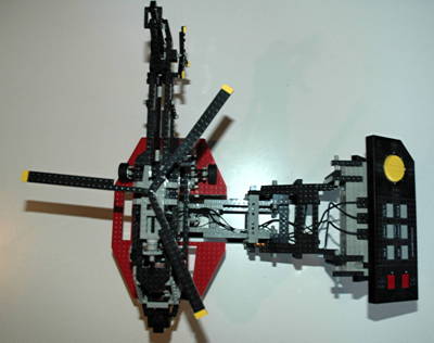
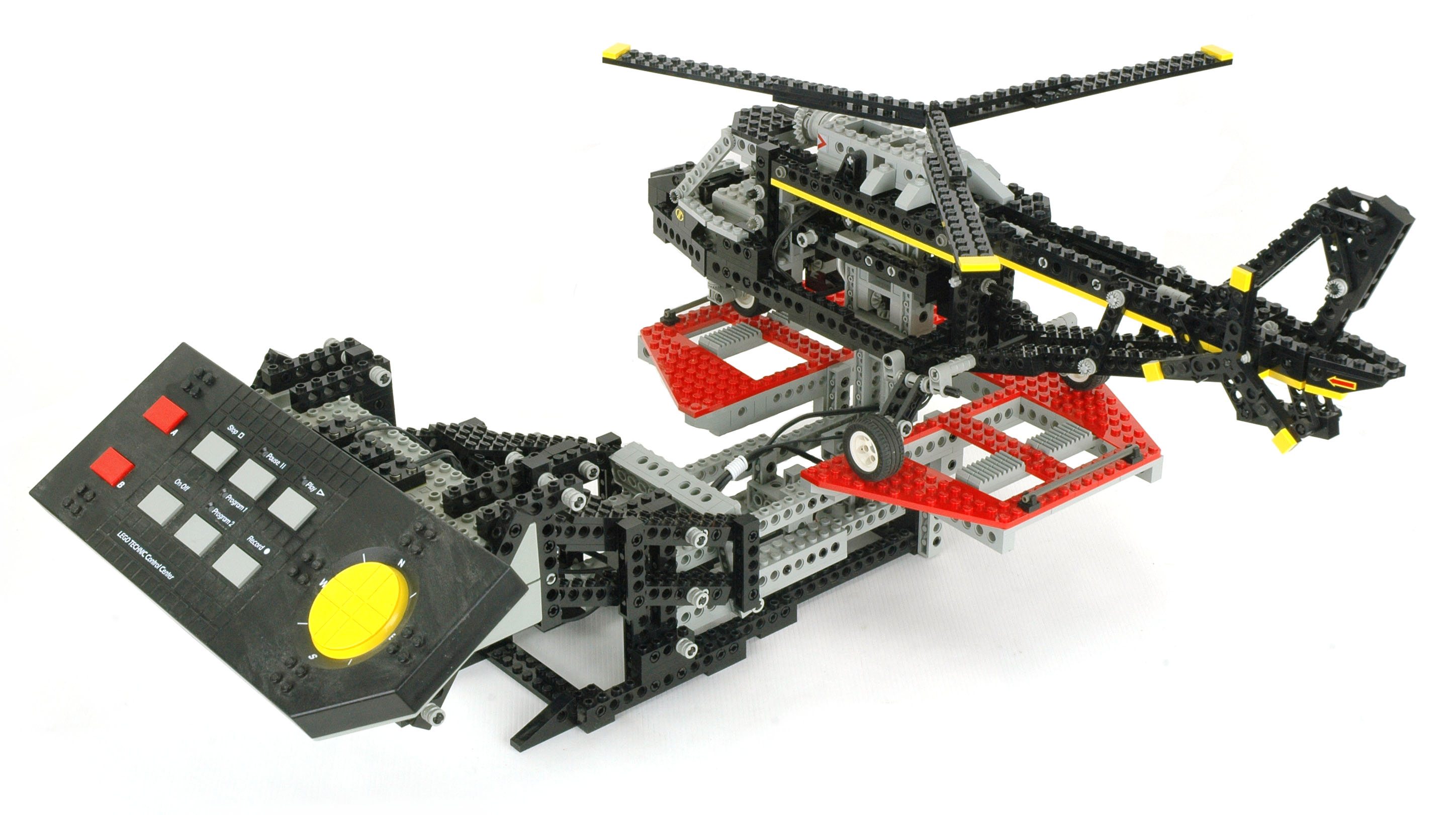
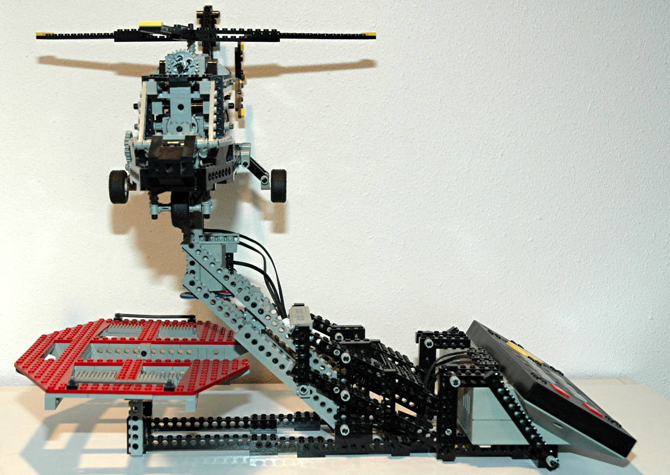
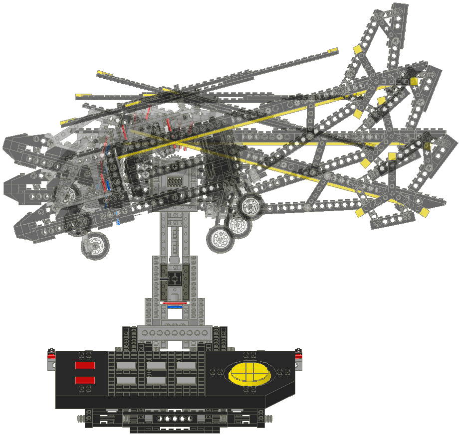
This
marvelous
helicopter
is nearly the best ever produced in the Technic
line with the possible exception of 8856.
Its
list
of functions is large (and so is the model), but what really
makes it stand apart is the way that it can actually be "flown" like a
flight simulator.
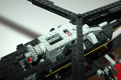
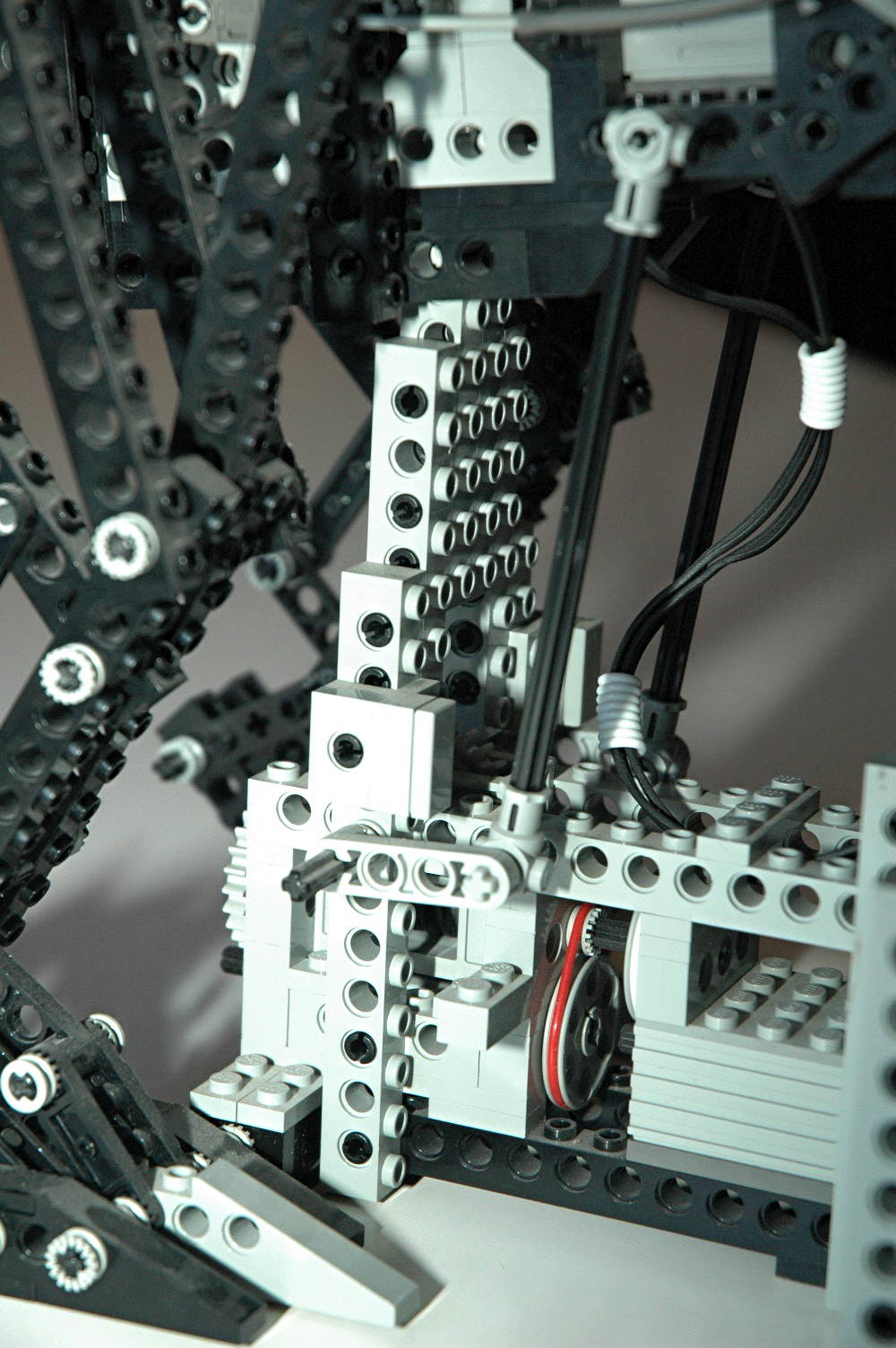
The 3 motors are integrated such that they can hardly be noticed, and
even the wiring tucks away and is bundled with a rare set of silicone
helical loops (seen in some of the photos in white).
|
Click to download the LDraw
file of this model.
Model by Benjamin Wendl
Click for an animation of
the helicopter in motion.
|
|
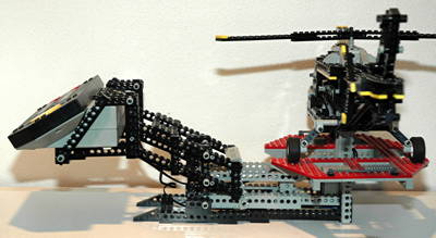
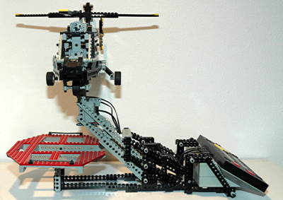
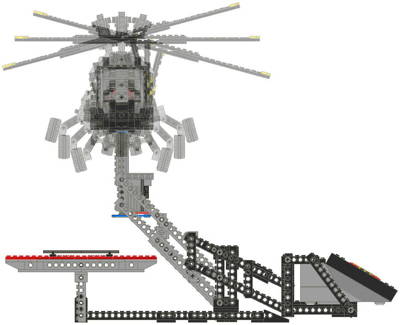
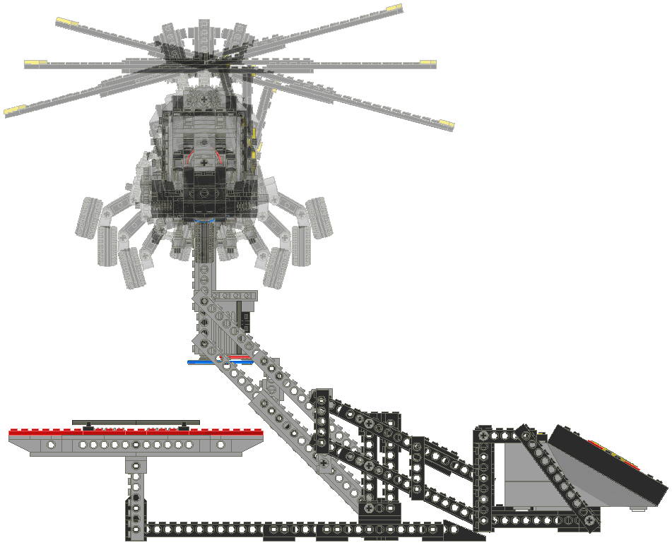
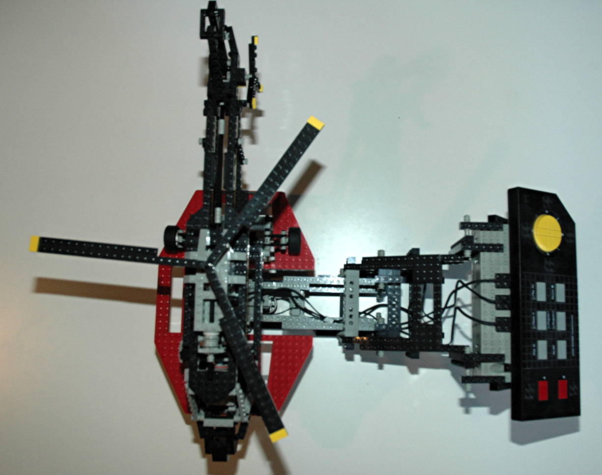
Elevation
The mechanism for controlling elevation of this helicopted is
ingenious. The Control Center is actually used as a counterweight
which acts against the helicopter via a pair of 4-bar linkages.
Depression of the Control Center raises the helicopter. The
weight and lever arm are accurate enough a counterbalance (with the
addition of internal friction) that the helicopter stays up. When
the Control Center is lifted, the helicopter descends into a gentle
landing on the attached landing pad. The landing pad is static
and remains at the same level. Note that batteries must be
installed in the Control Center (even if you are not using them) to get
the balance right.
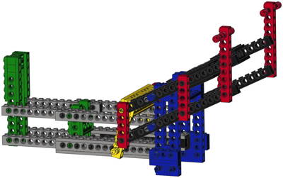
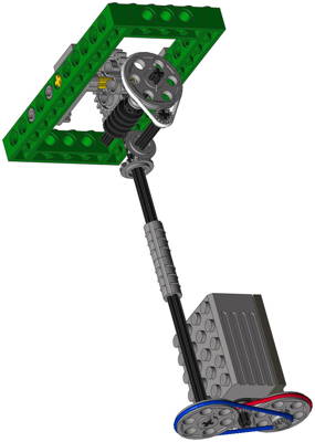
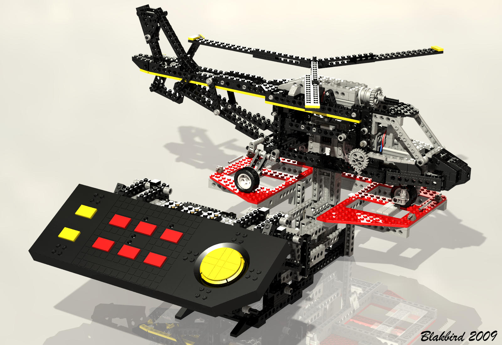
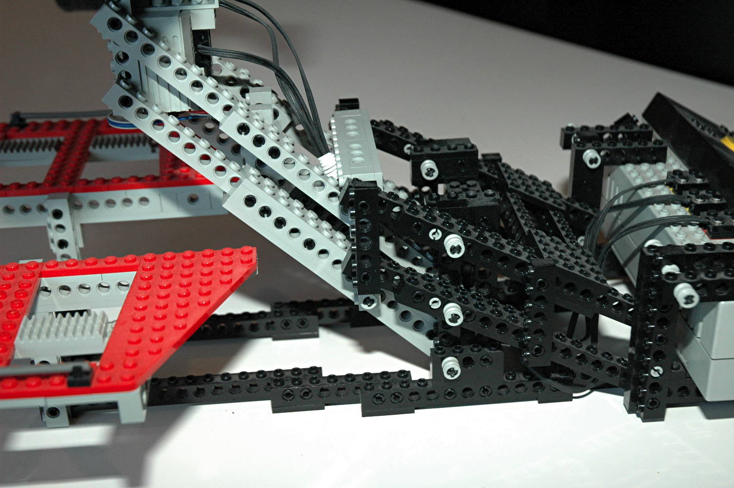
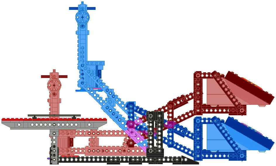
The mechanism to control the elevation is rather complex and is
pictured at right. In consists of a pair of nested 4-bar linkages
which are linked via a central connection.
The outer linkage is made from mostly black beams and supports the
Control Center. The computer image shows the horizontal links in
black and the vertical links in red. Items of the same color
remain parallel throughout motion which keeps the Control Center
parallel to the ground.
The inner linkage is made mostly from gray beams and support the
helicopter. The computer image shows the horizontal links in gray
and the vertical links in green. Items of the same color remain
parallel throughout motion which keeps the helicopter mount
perpendicular to the ground.
Both linkages are attached to ground at the structural tower shown in
blue and are each pinned there on two axes. The yellow link is
the key to the whole thing. It couples the motion of the inner
and outer linkages, connecting to them at the pins shown in yellow.
The final image shows the raised and lower positions superimposed for
comparison. Note the fact that the helicopter linkage moves a
greater vertical distance than the Control Center linkage. This
is due to the fact that the yellow coupling attaches to the inner
linkage one stud further from the rotation axis than it does to the
outer linkage.
Elevation change is the only non-motorized function of the model.
|


Image
by Benjamin Wendl
Click for an animation of the
elevation in motion.
|
|
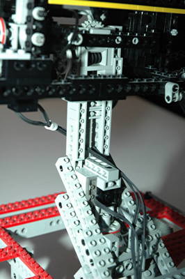
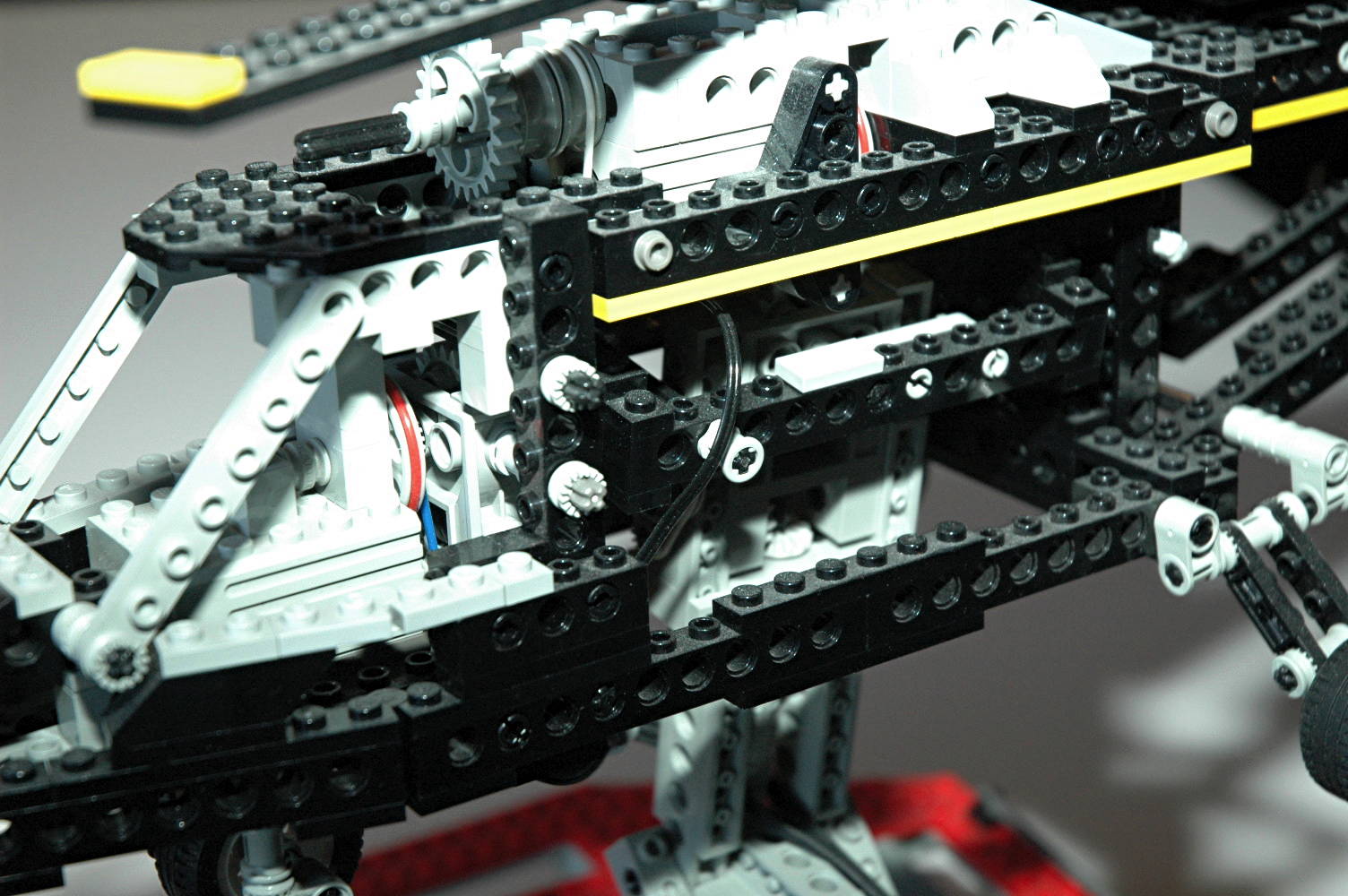
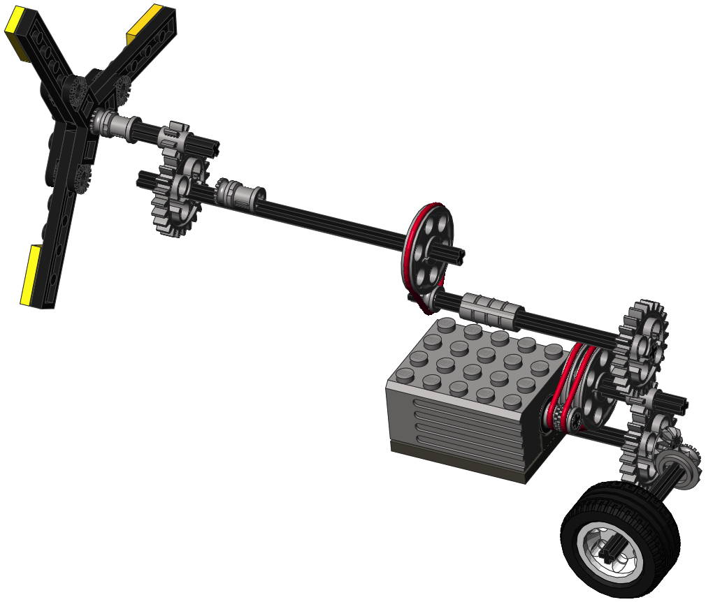
Pitch
The pitch of the helicopter is motorized and controllable via the side
to side motion of the control pad. The motor which drives this motion
is housed in the vertical portion of the stand which raises and lowers
with the entire model.
The helicopter is mounted to the stand with a box structure called a
gimbal. It can rotate on two axes independently or together:
pitch and roll. A worm gearbox in the stand allows the pitch
rotation nose up and down about 40 degrees.
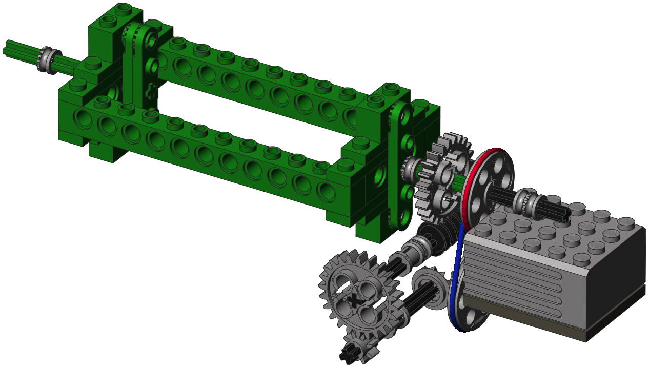
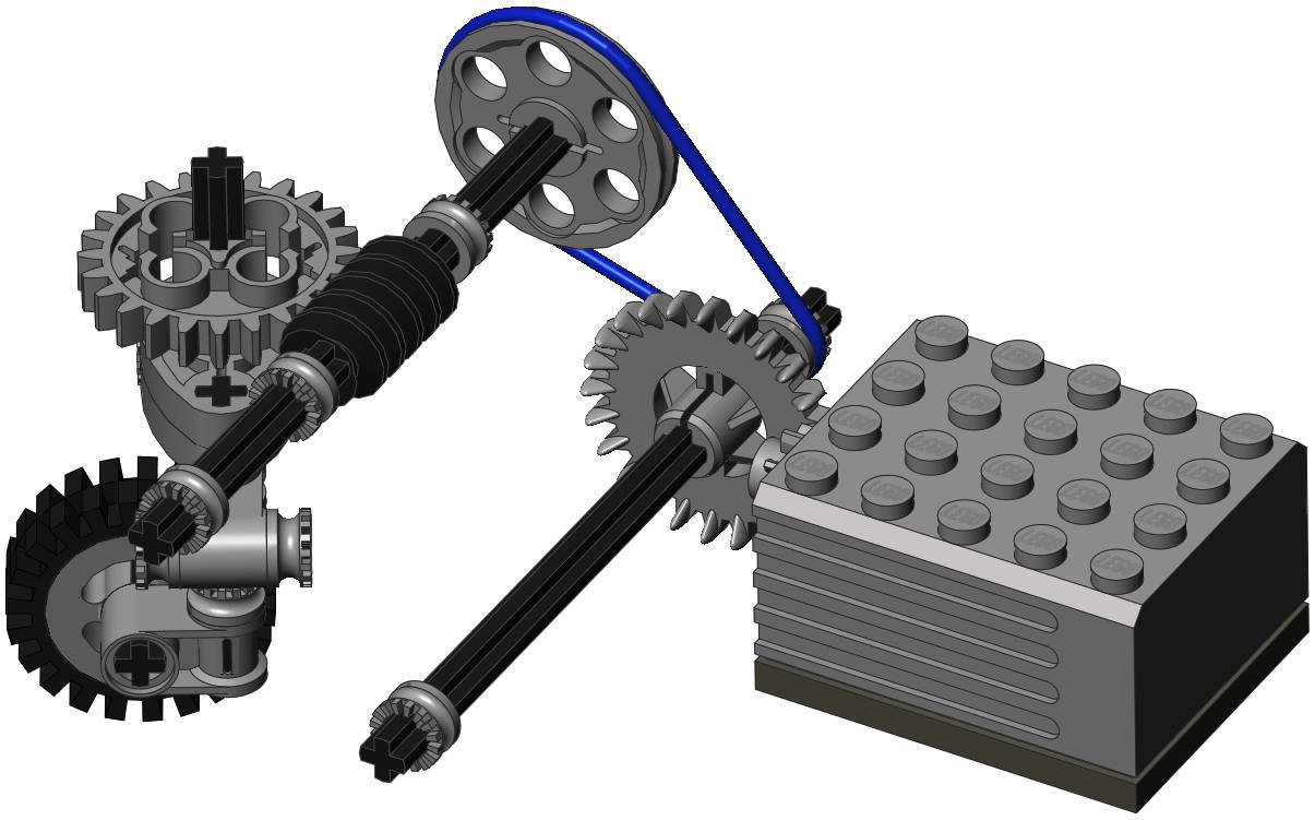
As can be seen in the computer image, the high speed motor drives
through 2 different silicone belts (red and blue). The use of
belts rather than gears allows the pulleys to slip rather than stall
the motor when the helicopter hits the stops. Each stage of drive
belt results in a reduction of about 3:1. A set of bevel gears
then drives torque into a third belt (white) which drives a new worm
gearbox (hidden). The gearbox both drives and supports a 24 tooth
spur gear. The axle at the center of this spur gear (shown in
yellow) is coupled to the gimbal (shown in green) with a pair of
liftarms such that rotation of the axle directly produces rotation of
the gimbal. Because a worm gear is used, the model maintains the
attitude at which it was last positioned.
The movement is quite slow thanks to the total gear reduction of (3:1 x
3:1 x 12:12 x 3:1 x 24:1) = 216:1.
The final image shows the nose up and down positions superimposed for
comparison.
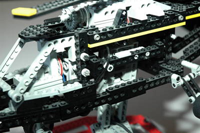
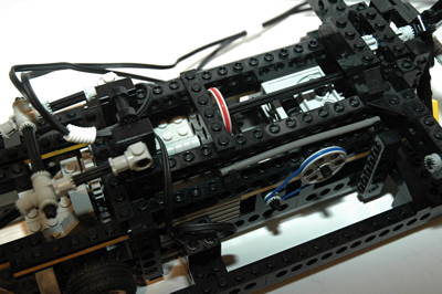
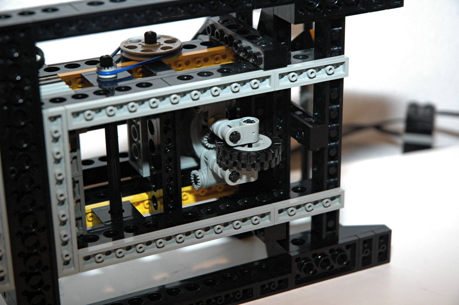
Note in the photographs that a number of wires have to be carefully
routed through this area without interfering with the motion of the
parts.
|
Image
by Benjamin Wendl
Click for an animation of the
helicopter pitching. |
|
Roll
The roll of the helicopter is motorized and controllable via the up and
down motion of the control pad. The motor which drives this motion
is housed in cockpit of the helicopter model.
The helicopter is mounted to the stand with a box structure called a
gimbal. It can rotate on two axes independently or together:
pitch and
roll. A worm gearbox in the body allows roll port and starboard
about 20 degrees. I wouldn't want to roll much further than this
in a helicopter.
As can be seen in the computer image, the high speed motor drives
through 2 different silicone belts (red and blue). The use of
belts
rather than gears allows the pulleys to slip rather than stall the
motor when the helicopter hits the stops. Each stage of drive
belt
results in a reduction of about 3:1. A set of bevel gears then
drives
torque into a set of 8 and 24 tooth spur gears on the right side of the
body. Finally, a worm gearbox (hidden) drives and supports the
green axle of the gimbal with a pair of rotors such that rotation of
the axle
directly produces rotation of the gimbal. Because a worm gear is
used, the model maintains the attitude at which it was last positioned.
The movement is quite slow thanks to the total gear reduction of (3:1 x
3:1 x 12:12 x 24:8 x 24:1) = 216:1.
The final image shows the roll positions superimposed for
comparison.
|
Image
by Benjamin Wendl
Click for an animation of the
helicopter rolling. |
|
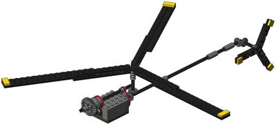
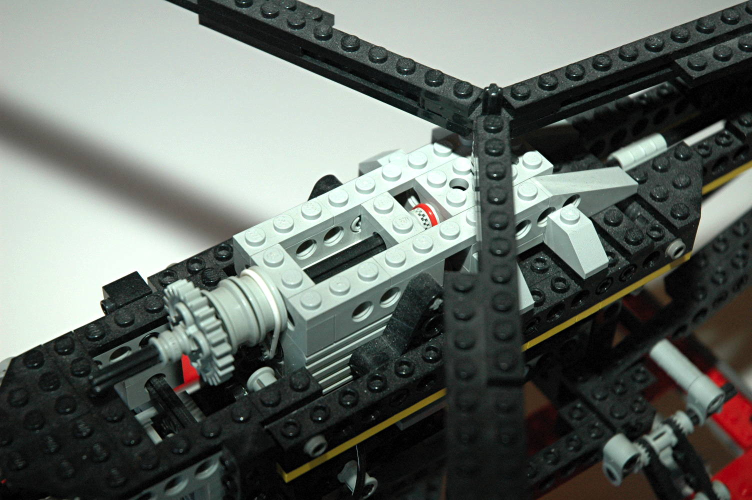
Rotors
Like virtually all Technic helicopters, the main and tail rotors
rotate. In this case, they are motorized to turn at the same rate
via a motor located in the body at the approximate position a turbine
would be located in a real helicopter. The large A and B buttons
on the Control Center command the rotor motion clockwise or
counter-clockwise.
As can be seen in the computer image (best seen by zooming in) the high
speed motor drives
through 2 different silicone belts (both red). The use of belts
rather than gears allows the pulleys to slip rather than stall the
motor when the rotor is started or stopped. Each stage of drive
belt
results in a reduction of about 3:1. A set of bevel gears drives
both the main and tail rotors.
The 24 tooth gear at the front of the assembly does not actually do
anything, it is merely meant to represent the spinning compressor fan
of a turbine.
It is not immediately obvious from simply playing with the Control
Center, but the manual tells you how to lock the rotors on so the
buttons don't have to be held. If the A and B buttons are pressed
together and then only one is released, the function will stay on until
another red button is pressed.
|
Click for an animation of the
rotors in motion. |
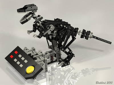
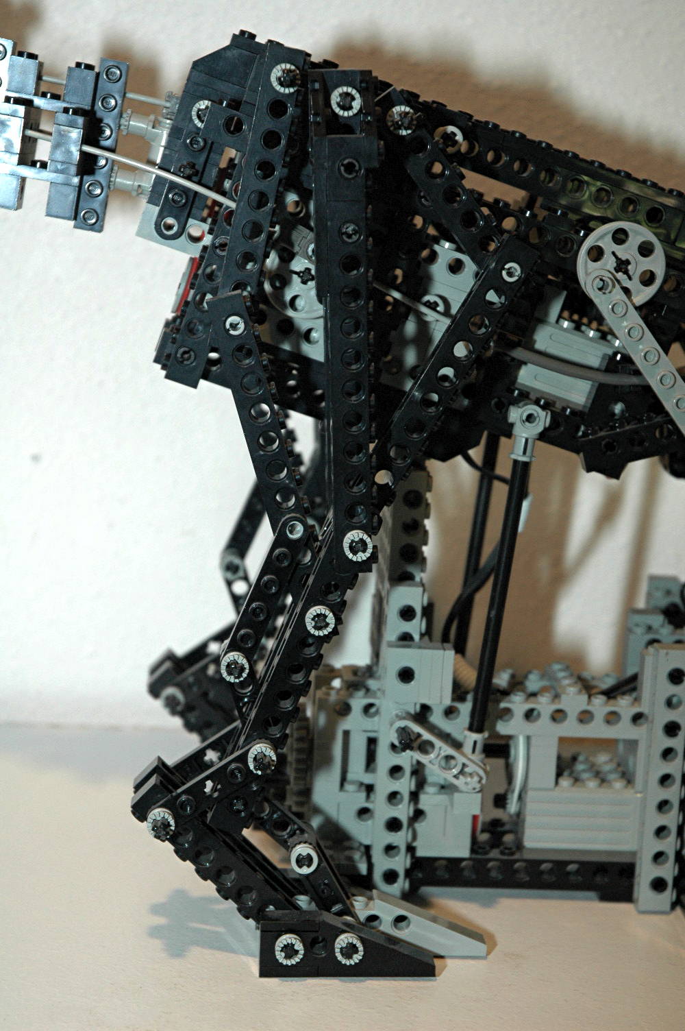
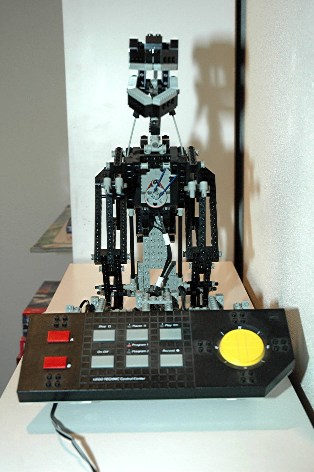
2nd
Model: Dinosaur
|
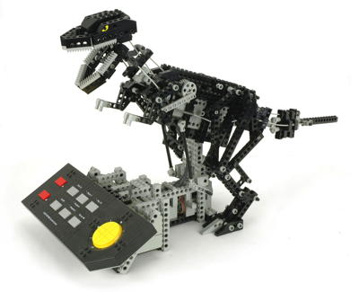
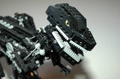
This
dinosaur
(presumably
a Tyrannosaur) is one of my favorite models
ever. Firstly, it is a Technic model which is not a piece of
machinery which makes it a rare breed indeed. It is the only
biologic form ever produced in Technic, and the motion produced by the
three motors is nothing short of magnificent. Each control in and
of itself is lovely to watch, but the beauty of the Control Center is
that all three can be operated concurrently.
This dinosaur is supported by and integral with a gray stand which
contains the Control Center.
This model uses the Flex System more significantly than any other
model, and probably to the best effect. The organic movements
would be much more difficult to replicate with gear systems.
|
Click to download the LDraw
file of this model.
Model by
Benjamin Wendl
Click for an animation of
the dinosaur in motion. |
|
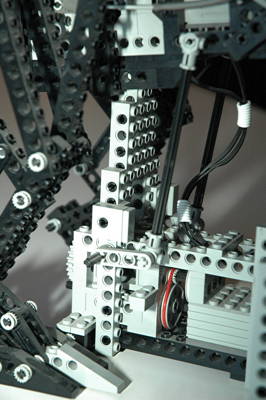
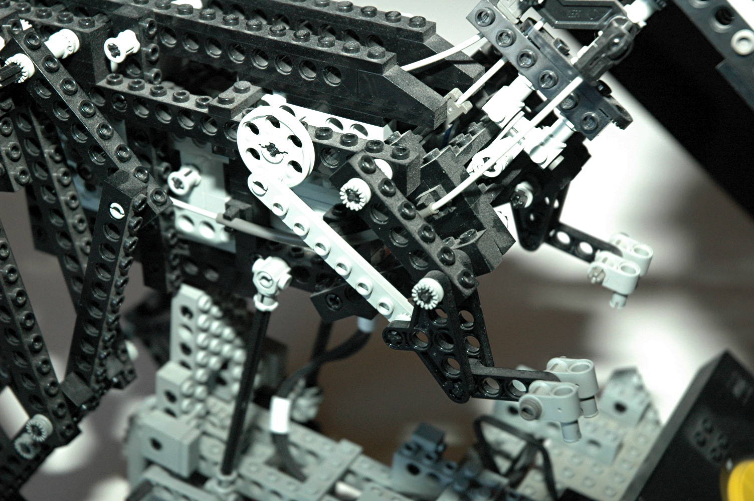
Bending
The dinosaur can bend down and lower its head almost to the Control
Center using a motor mounted in the support stand. As can be seen
in the computer image, the high speed motor drives
through 2 different silicone belts (red and white). The use of
belts
rather than gears allows the pulleys to slip rather than stall the
motor when the dinosaur bends fully. Each stage of drive belt
results in a reduction of about 3:1. A set of 24 and 8 tooth spur
gears then drives a worm gearbox. The output axle (shown in green)
turns a pair of liftarms which use push rods to rotate the dinosaur at
its pivot axle on the stand. Because a worm gear is used,
the model maintains the attitude at which it was last positioned.
The movement is quite slow thanks to the total gear reduction of (3:1 x
3:1 x 24:8 x 24:1) = 216:1.
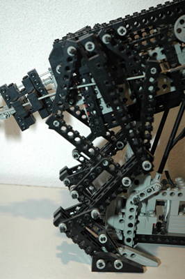
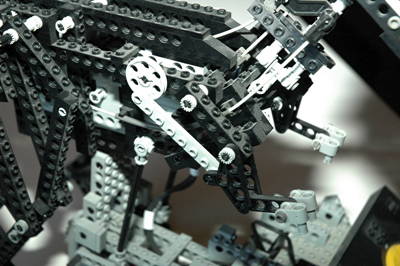
The lower set of pictures shows the complex geometry of the legs which
mimics the (estimated) musculature of a real creature. A
comparison of the images at the two extreme positions shows the change
in muscle and tendon geometry. This can be further appreciated in
the animation.
|

Click for an animation of
the dinosaur tipping.
|
|
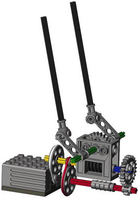
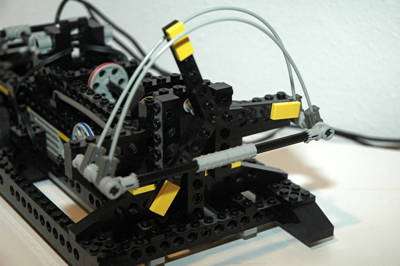
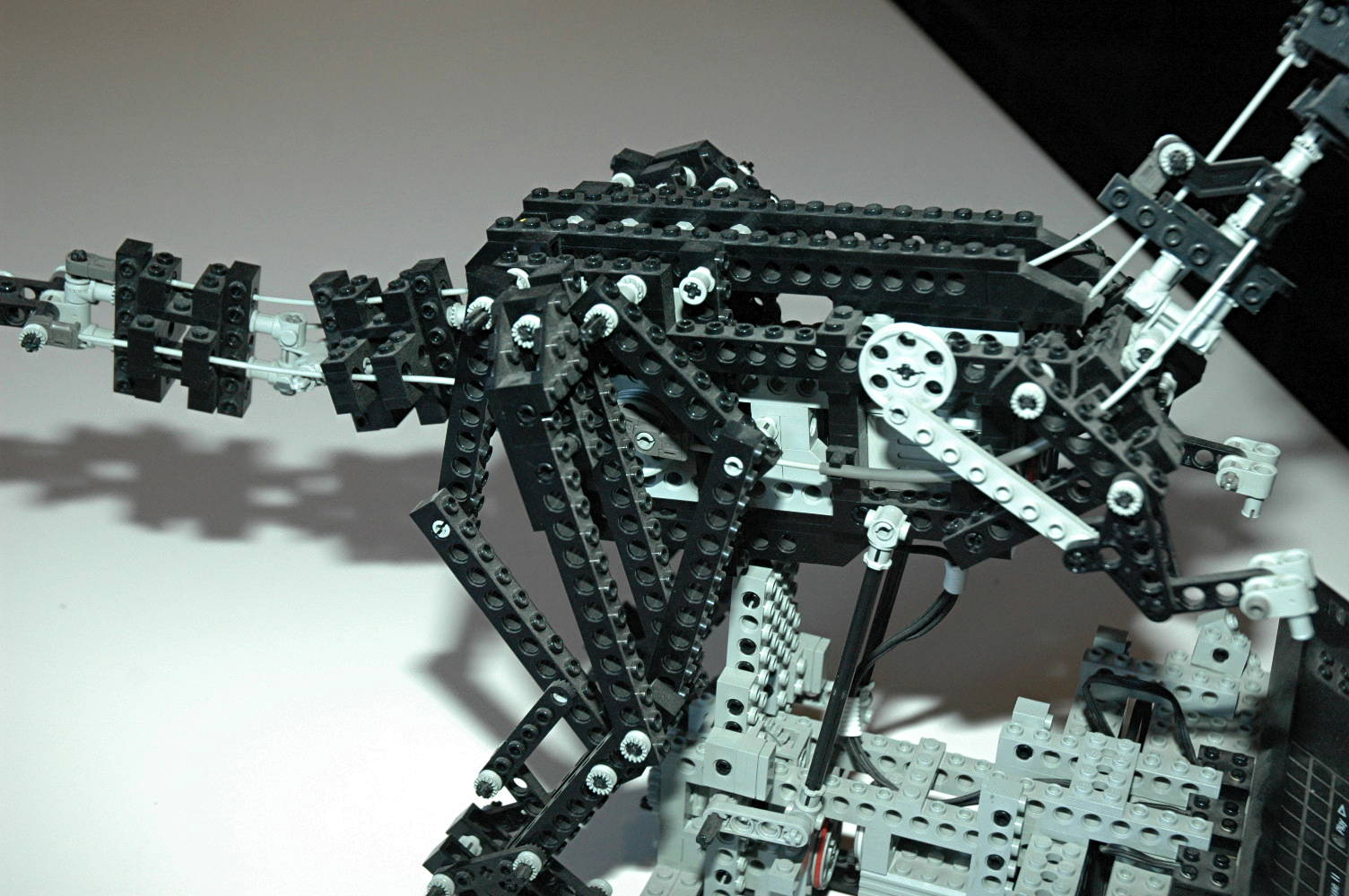
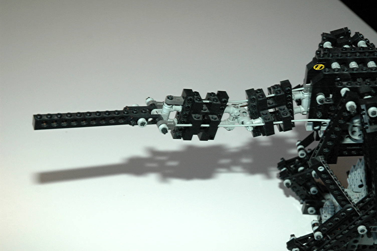
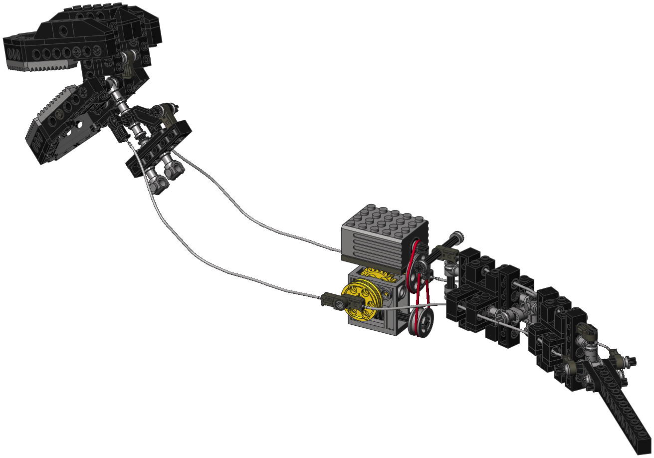
Tail and Head
The tail and head wag side to side using a motor in the back of the
torso via a system of flexible cables. The head and tail are
linked together so that they move in unison. This is a reasonable
assumption since a creature with such a massive head would need to use
the tail for counter balance.
As can be seen in the computer image, the high speed motor drives
through 2 different silicone belts (red). The use of belts
rather than gears allows the pulleys to slip rather than stall the
motor if the resistance becomes too high. Each stage of drive
belt
results in a reduction of about 3:1. The second pulley drives a
worm gearbox. The output pulleys (shown in yellow) are used as
cranks. The left and right side are 180 degrees out of phase and
each holds a pair of flex cable ends. Both the head and the tail
form a pull-pull loop. Movement of the forward cables tips the
head side to side, and movement of the rear cables swings the tail side
to side. Because a worm gear is used,
the model maintains the attitude at which it was last positioned.
The total gear reduction is (3:1 x 3:1 x 24:1) = 72:1.
The tail is hinged in three places horizontally, allowing it to forma
gentle curve. It does not bend vertically, and the extra flex
cable on the top helps to support the weight.
|


|
|
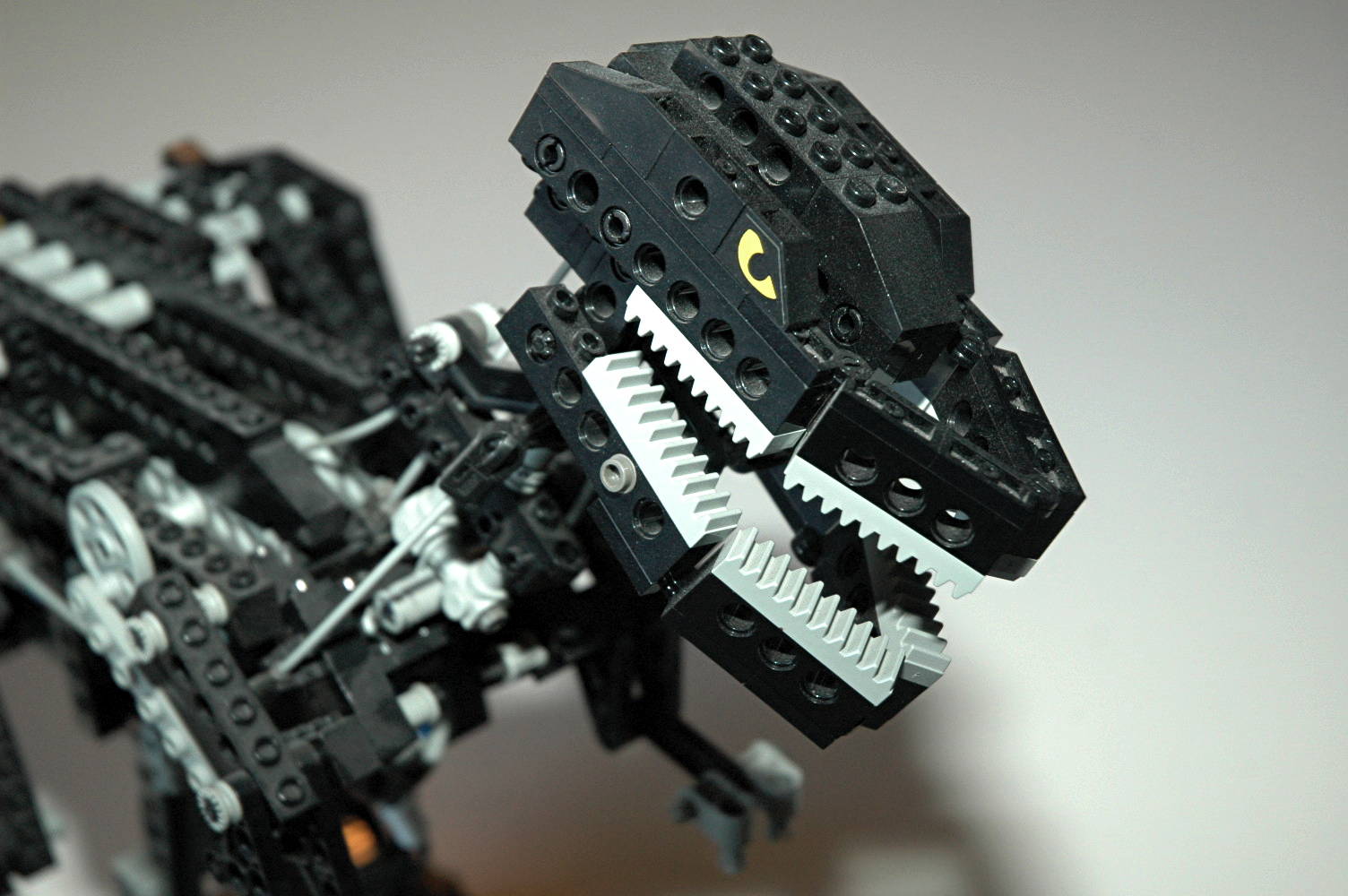
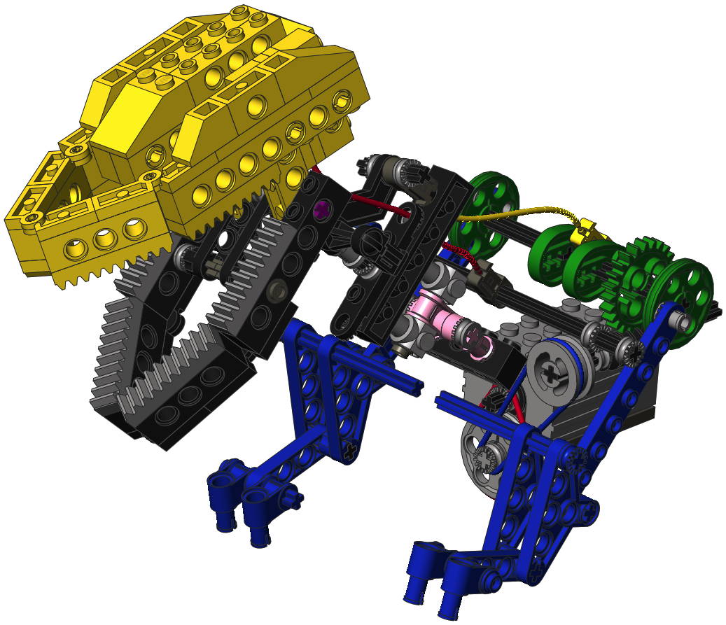
Arms and Jaw
The arms swing up and down and the jaw opens and closes using a motor
in the front of the torso. The arms and jaw are linked
together so that they move in unison.
As can be seen in the computer image, the high speed motor drives
through 2 different silicone belts (red and blue). The use of
belts
rather than gears allows the pulleys to slip rather than stall the
motor if the resistance becomes too high. Each stage of drive
belt
results in a reduction of about 3:1. The second pulley drives a
worm
gearbox (hidden). The output pulleys (shown in green) are used as
cranks. The
left and right side are 180 degrees out of phase. The cranks
oscillate the blue arms up and down. Because a worm gear
is used,
the model maintains the attitude at which it was last positioned.
The total gear reduction is (3:1 x 3:1 x 24:1) = 72:1.
In addition to the green pulley cranks, on the same axle are a pair of
cams shown in green and also used as cranks. A flex axle connects
here (shown in yellow) and attaches to the movable upper jaw.
Oddly, the lower jaw does not really move but rather is fixed at a 90
degree and to the neck which does move. The upper jaw pivots on
the purple axle when the entire head is lifted by the yellow cable
around the pink axle. The red flex cable supports the weight of
the head and remains fixed in position while the yellow cable performs
the movements.
|

|
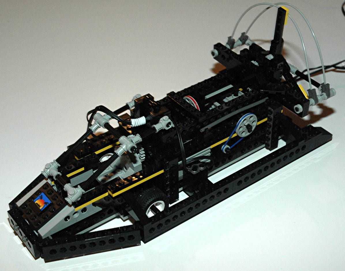
3rd
Model: Boat
|
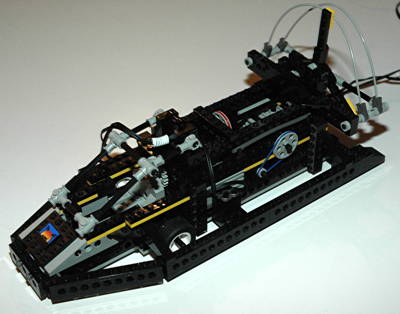
The
third model, and airboat, is not nearly as inspired as the other two
but is still an excellent model. It uses two of the three
available motors and about half of the parts. It is
tethered to the Control Center via wires which are not really long
enough to allow you to stand up and follow the model along while it
drives along the floor.
|
 Click
Click to download the LDraw
file of this model.
Model by Benjamin Wendl
|
|
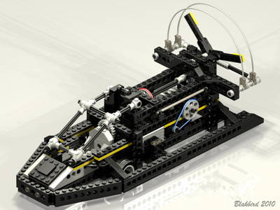
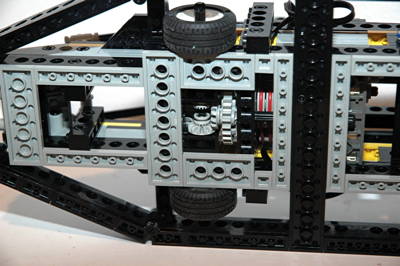
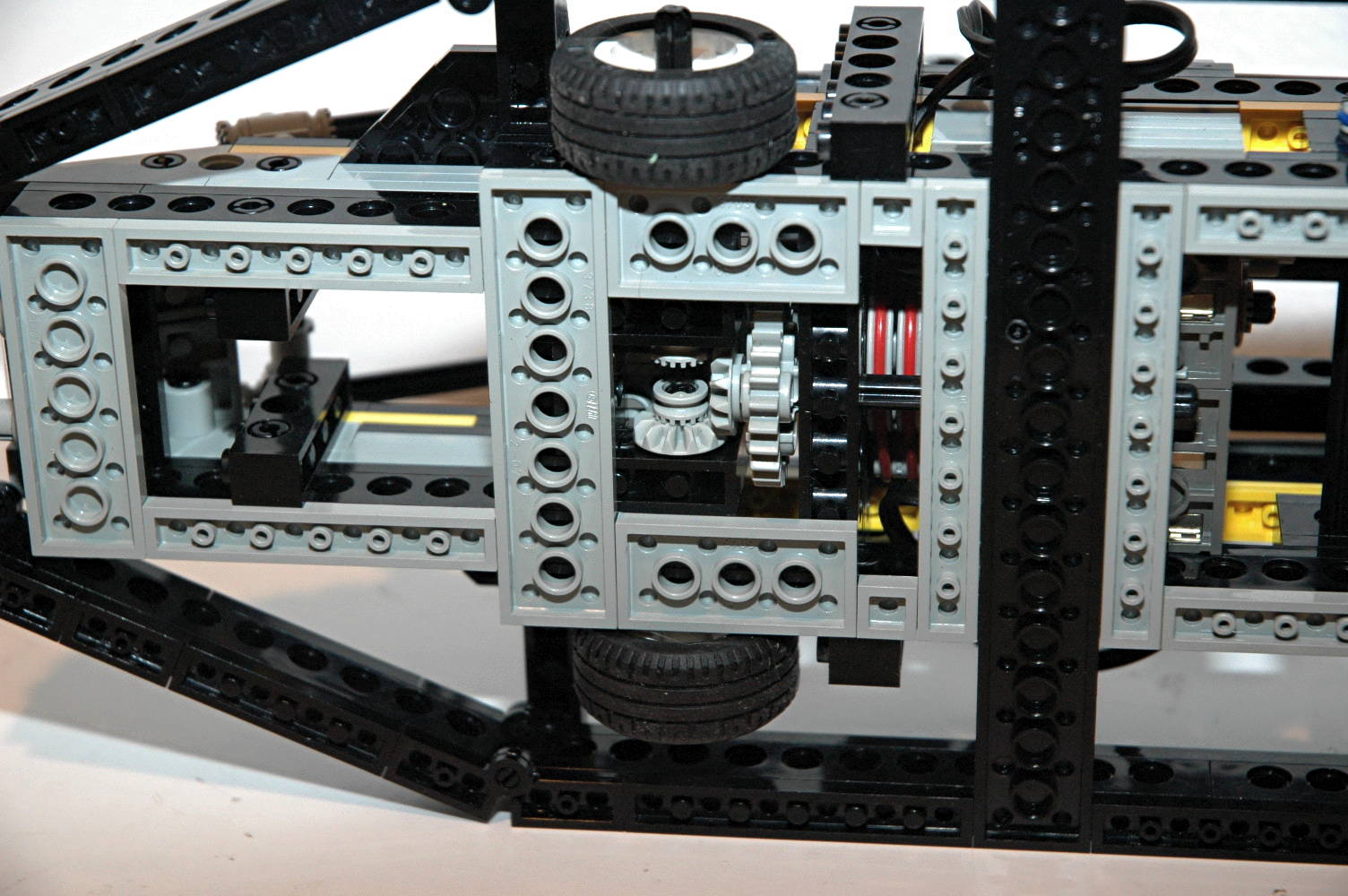
Fan and Drive
System
The model is supported on three hidden tires behind the skirt, two in
the front and one in the rear. One of the front wheels is used
for actual propulsion while a large fan in the rear is used to simulate
the propulsion method of a real air boat.
As can be seen in the computer image, the high speed motor drives
through 3 different silicone belts (red). The use of belts
rather than gears allows the pulleys to slip rather than stall the
motor if the resistance becomes too high. Each stage of drive
belt
results in a reduction of about 3:1. The first stage is actually
two belts in parallel which drive an 8 tooth pinion gear. At this
point the gear system splits into two parallel paths.
The lower path drives into a 24 tooth spur and then a pair of 12 tooth
bevel gears. The final axle drives the wheel. The total
gear reduction is only (3:1 x 24:8 x 12:12) = 9:1. The use of a
drive wheel on only one side effectively acts as a differential
allowing the front wheels to turn at different speeds.
The upper path also drives a 24 tooth spur which is then followed by
another set of pulleys with a red belt. A final reverse gear
ratio using spur gears actually speeds the propeller back up. The
total gear reduction is (3:1 x 24:8 x 3:1 x 8:24) = 9:1.
|
Click for an animation of the fan in
motion.
Click for an animation of the
drive system in motion.
|
|
Steering
The hidden rear wheel can be steering using a second motor in the body.
As can be seen in the computer image, the high speed motor drives
through a silicone belt (blue). The use of belts
rather than gears allows the pulleys to slip rather than stall the
motor if the resistance becomes too high. Each stage of drive
belt
results in a reduction of about 3:1. A pinion gear on the motor
drives a 24 tooth crown which then drives the belt system. A worm
gearbox (hidden) is then used to drive a 24 tooth gear into the
steering axle. The total gear reduction is (24:8 x 3:1 x 24:1) =
216:1.
Because of the significant steering angle and the fact that the
steering is located in the rear, the model can turn on a very tight
radius.
|


Click
for an animation of the steering in motion.
|


