Features
|
|
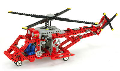
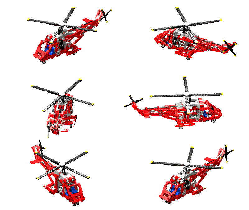
Rotors
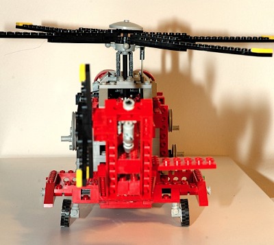
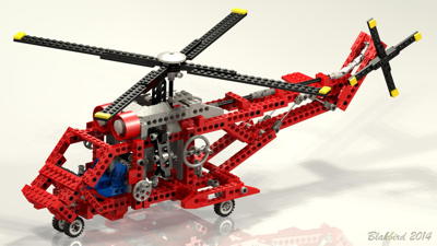
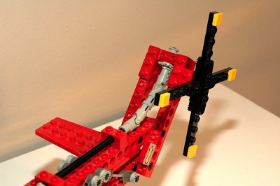
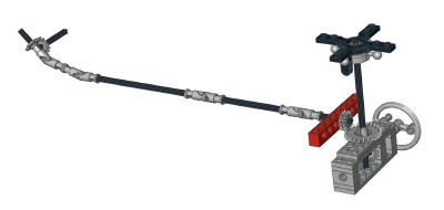
The rotors' rotation is driven by an input crank on the left
side. This crank drives a set of 14 tooth bevel gears giving the
main
rotor a ratio of 1:1. The crank axle also drives a set or gears
made up of a 24 tooth crown mating with two stacked 14 tooth bevel
gears (one of the rare places this pairing is made) which passes torque
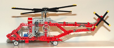
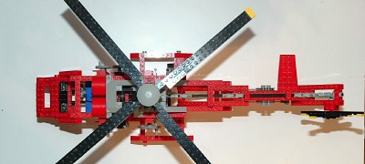
along the length of the boom to the
tail through 3 universal joints. Here another set of 14 tooth
bevel gears drives the 4 blade tail rotor.
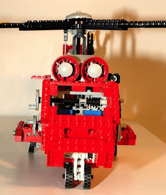
A pair of simulated turbine engines are nestled beneath the main rotor
head.
|
Ldraw file courtesy of
Benjamin Wendl.
Click for an animation of the
rotors
in
motion.
|
|
Cyclic Pitch
A number of new parts made a simulated cyclic system possible.
Real helicopter cyclic works by changing the pitch of individual blades
as they rotate using a swashplate. For example, the leading and
trailing blades may be at 10 degrees of pitch, while the port and
starboard blades are at 5 and 15 degrees respectively. This model
pivots the entire rotor head instead. If a real helicopter did
this it would risk striking the rotor against the frame.
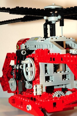
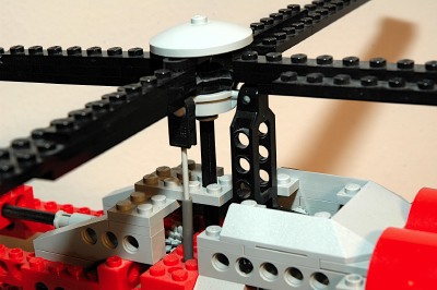
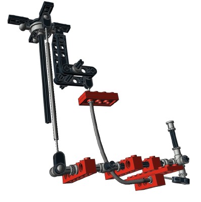
The rotor axle drives a spherical ball gear. A part with 4
ball joints which is similar to a swashplate connects to a pair of flex
cables to allow the head to pivot on two axes. The ball joints
also keep the swashplate from rotating. Inside the swashplate is
a four blade rotor part. The rotor has tabs on the inside which
mate with the ball gear to transmit torque. Because of the
shape of the gear, the rotor can pivot on two axes while still rotating.
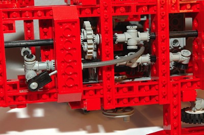
The control of the cyclic is from a stick at the pilot's
position. There is one flex cable and sleeve for each axis.
Fore-aft motion of the stick pushes and pulls the cable using a ball
joint. The flex cable runs up to a link which lifts the
swashplate using a suspension control arm! Lateral motion of the
stick rotates an axle which runs aft. At the end of the axle is a
ball joint which connects to another flex cable. This flex cable
attaches to a ball joint on the side of the swashplate.
|
Ldraw file courtesy of
Benjamin Wendl.
Click for an
animation of the cyclic
in motion. |
|
Landing Gear
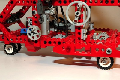
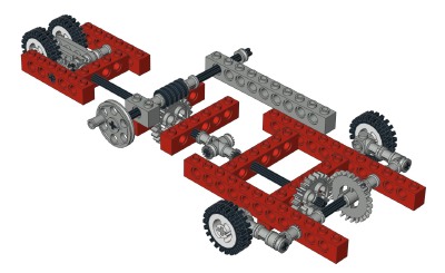
The 3 point landing gear retracts using another crank on the port
side. The crank turns a worm gear which mates with a 24 tooth
spur gear. The spur gear drives an axle which runs both forward
and aft. The nose gear retracts forward via a set of 14 tooth
bevel gears. The main gear pivots forward via a 24 tooth crown
and spur gear. The final gear ratio is 24:1.
Each gear pivots a little over 90 degrees. In both the extended
and retracted positions the gear rests against a hard stop.
|
Ldraw file courtesy of Benjamin Wendl.
Click for an animation of the landing
gear in
motion.
|
|
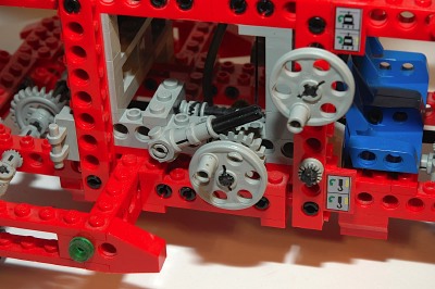
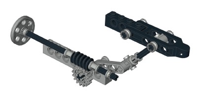
Rescue Winch
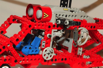
A pair of cranks on the starboard side operate the rescue winch on the
port side.
The first crank turns a worm gear which drives a 16 tooth spur
gear. The next axle pivots a lift arm which deploys the winch
boom.
The second crank attaches to a 16 tooth spur gear used as a ratchet
plate. A set of 14 tooth bevel gears drive the second axle which
works as a cable drum. The cable runs out to the winch and
attaches to a metal hook.
|
Ldraw file courtesy of Benjamin Wendl.
Click for an animation of the winch
boom deploying.
Click for an animation of the
cable in motion.
|

