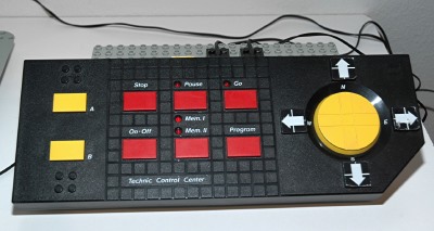
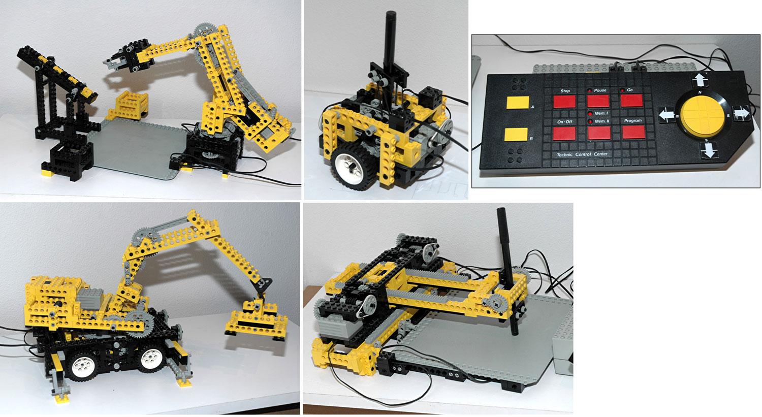
Control
Center
|
|
Control Center
The Control Center is the heart of this set. It was the first
programmable power system for LEGO® motors. There
is a battery compartment on the bottom which holds 6 C sized
batteries (LR14) in series, producing a total of 9 volts DC.
The Control Center has 3 color coded power outputs, each capable of
driving a 9V motor. The yellow output is labeled "A-B" and is
controlled by the two yellow buttons on the left with the same
labels. One buttons drives one direction, and the other reverses
polarity and drives the motor the other way. The red and blue
outputs are labeled "N-S" and "E-W". They are controlled by a 4
way control pad on the right. Movement of the control pad in a
diagonal direction effectively controls 2 channels at once.
The red buttons in the center control programming. There are two
memory sections which the Control Center can toggle between. Once
a memory is selected, you can push Program and the system will record
your inputs, including duration, and including pauses. When you
are done recording the program, you push Stop and it is stored to
memory, even if the unit is switched off. You can then play it
back (Go) at any time, or you can control the system manually.
There is obviously some limit to the amount of memory on the system so
it can only record a certain number of inputs, however, I have never
found the limit.
|
|
1st
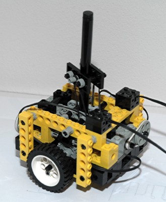
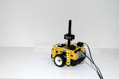
Model: Robot Plotter
|
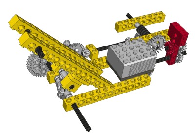
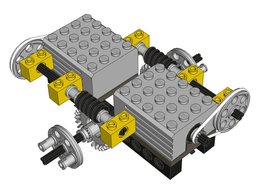
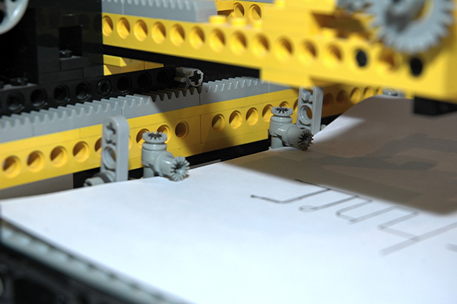
This
little
robot
is used to draw crude images. It rides on two wheels
and is balanced by pins at the other two corners. Each wheel is
powered by an independent motor. Since the wheels can be driven
in opposite directions, the robot is capable of turning with zero
radius.
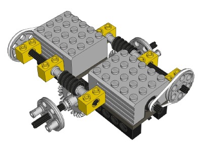
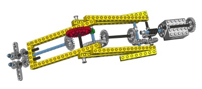
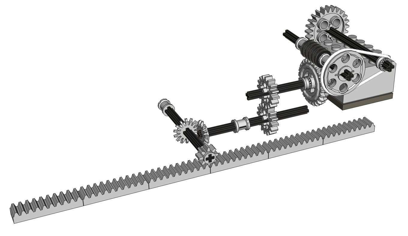
The computer image shows the drive system. Each motor drives a
pulley via a belt. The pulley then drives a 24 tooth crown gear
through a worm gear, resulting in a reduction of about 75:1.
A Technic pen is clamped in the center of the assembly with a pair of
threaded axles. The pen passes all the way through the assembly
to the paper. A pair rubber bands pull the pen down against the
paper.
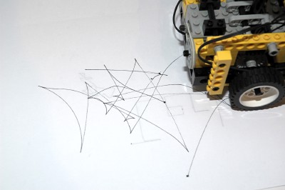
As you can see from the example image, it is pretty hard to draw
anything coherent with this system, but it is fun to try. The
animation is not real-time, but the jerky motion seen in it is still
indicative of how the robot really moves.
|
Click
to download the LDraw
file of this model.
Model by Benjamin Wendl
Click for an animation of
the robot in motion.
|
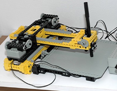
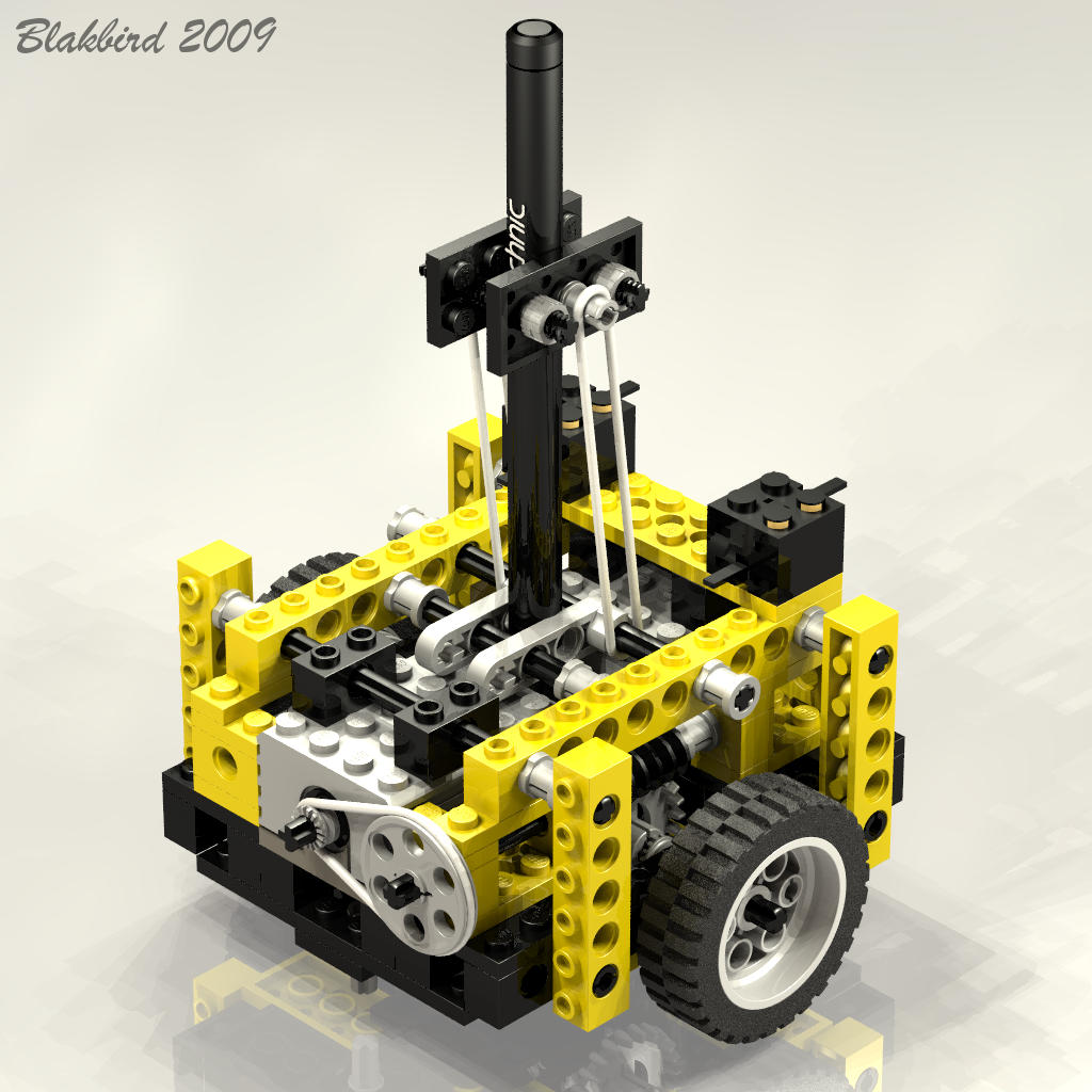
2nd
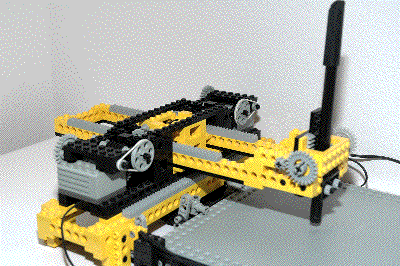
Model: Plotter
|
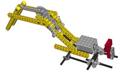
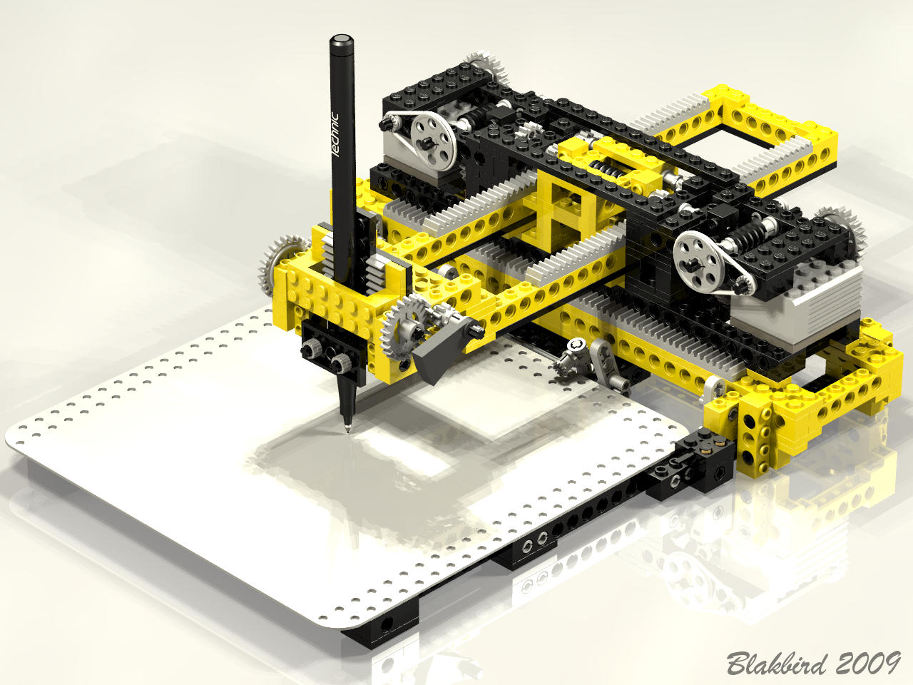
The
plotter is an exceptionally unique model, and a good simplification of
how
real servo motors driven by a programmable system might be used.
The plotter is motorized to translate along two axes independently (or
together). Diagonal lines are possible by running both motors
together, but tricky to do accurately. The remote control system
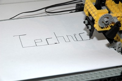
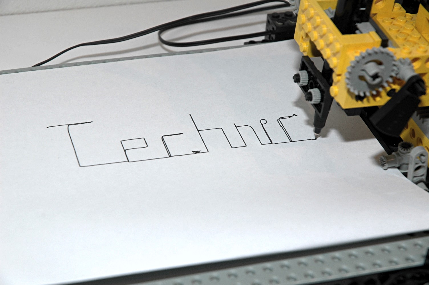
has no means to lift the pen, so the plot is typically one continuous
series of lines as shown in the example image. The pen can be
lifted manually.
The drawing method using the plotter is similar to the popular toy "Etch A Sketch".
|

Click to download the LDraw
file of this model.
Model by Benjamin Wendl
Click for an animation of
the plotter in motion. |
|
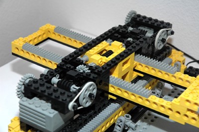
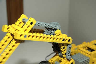
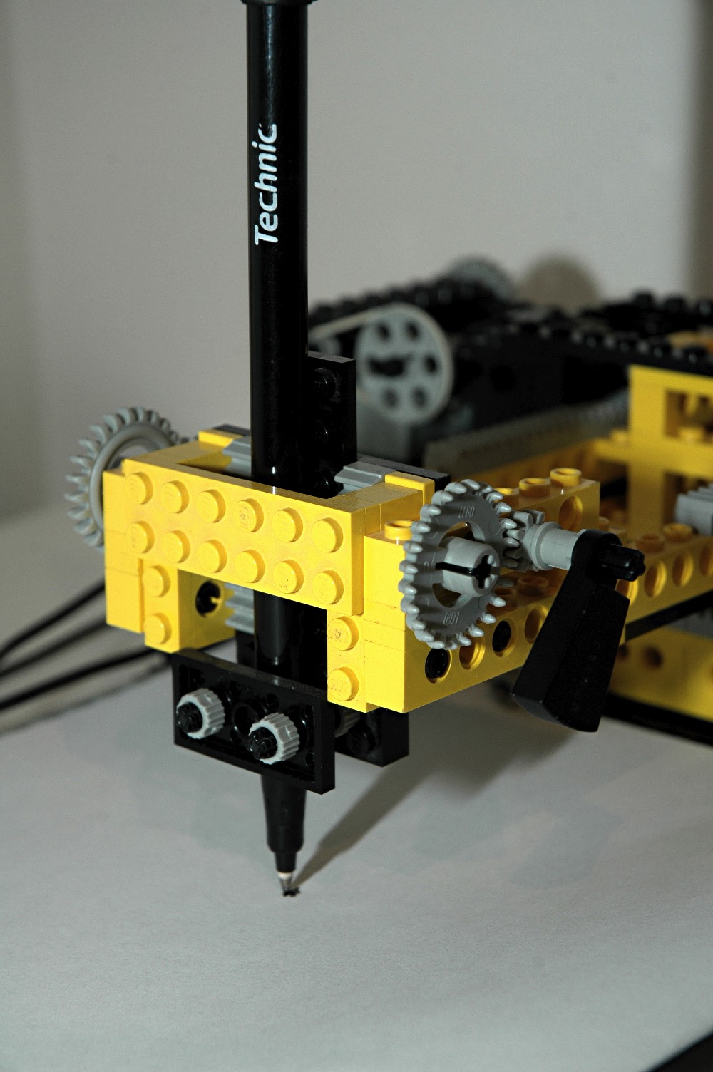
Pen and Paper
The Technic pen is supported at the end of the carriage arm and clamped
by threaded axles. A weighted element is used to push the pen
down against the paper. The weight has an axle slot at one
end. Since the weight is unbalanced, it tends to rotate the
axle. This force against the paper also tends to push the end of
the carriage arm up. The weight can be rotated to lift the pen
from the paper via the gear system. The weight drives a pair of 8
tooth spur gears. The gears drive 24 tooth crowns. On the
same axle are a pair of pinions which engage rack gears on the pen
clamp.
The plotter even includes a means to secure the paper. A
baseplate is used as a platform. A pair of toothed connnectors,
shown in the image, are preloaded against the paper with rubber bands
to hold it in place. This prevents the friction on the pen from
dragging the paper around the platform.
|

 |
|
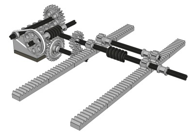
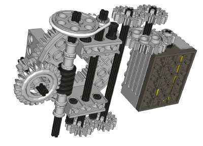
Motorized
Carriage
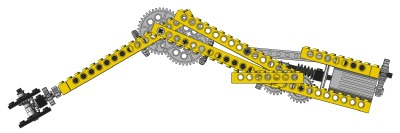
The carriage is motorized to translate on two axes. The motors
can be used independently to create horizontal or vertical lines, or
together to create diagonal lines. The motors drive at roughly
the same rate, so 0, 45, and 90 degrees are the only possible angles.
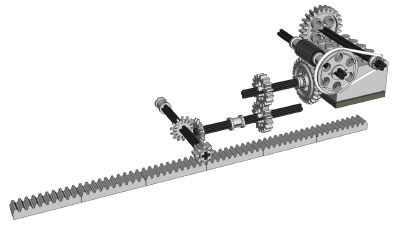
We'll call the side-to-side motion the X axis. The X axis motor
has an 8 tooth spur gear on the output shaft (first computer image) and
drives a 24 tooth spur gear. This drives through a set of pulleys
using a belt. The belt system allows the gears to slip instead of
stalling the motor when reaching the axis end stop. Next, a worm
gear drives a 24 tooth crown. The next two stages of 16 tooth
spurs and 14 tooth bevels are 1:1. Finally, an 8 tooth pinion
drives a long set of rack gears. Final reduction is about
216:1. The whole carriage slides on, and is supported by, tiles
on the base. It cannot slide far enough to become unbalanced and
fall off the side.
We'll call the front-to-back motion the Y axis. The Y axis motor
has an
8 tooth spur gear on the output shaft (second computer image) and
drives
a 24 tooth spur gear. This drives through a set of pulleys using
a
belt. Next, a worm gear drives a 24
tooth crown. The next stage is a pair of 16 tooth spurs.
Finally, a pair of 8 tooth pinions drive a long set of rack
gears.
Final reduction is about 216:1, the same as the X axis. The whole
carriage arm slides on, and is
supported by, tiles on the main carriage. A second set of pinion
gears engage the racks and prevent the cantilever moment from tipping
the arm off the carriage.
|
|
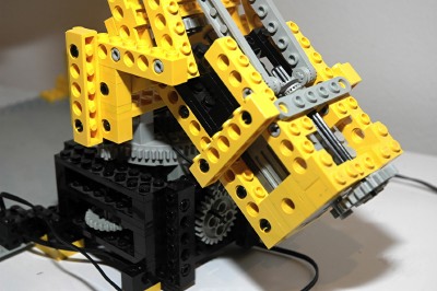
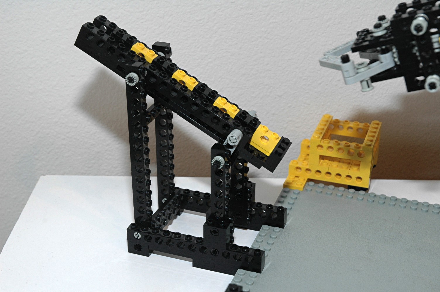
3rd
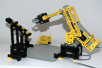
Model: Robotic Arm
|
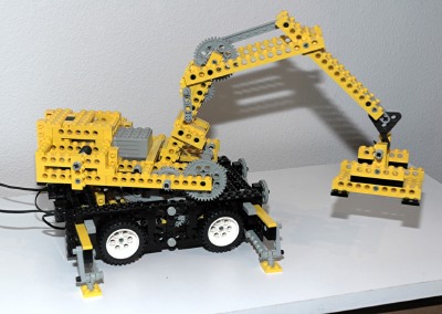
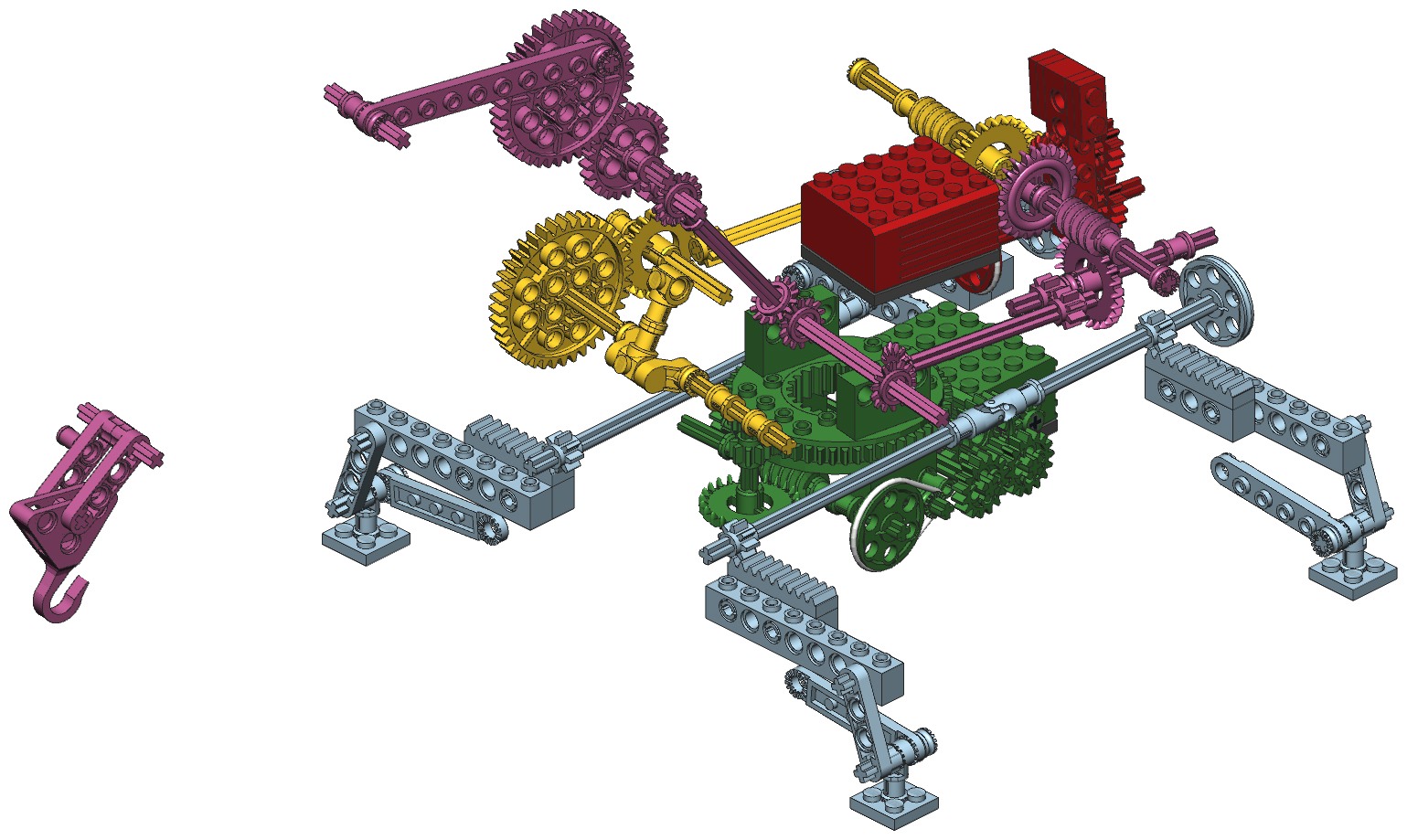
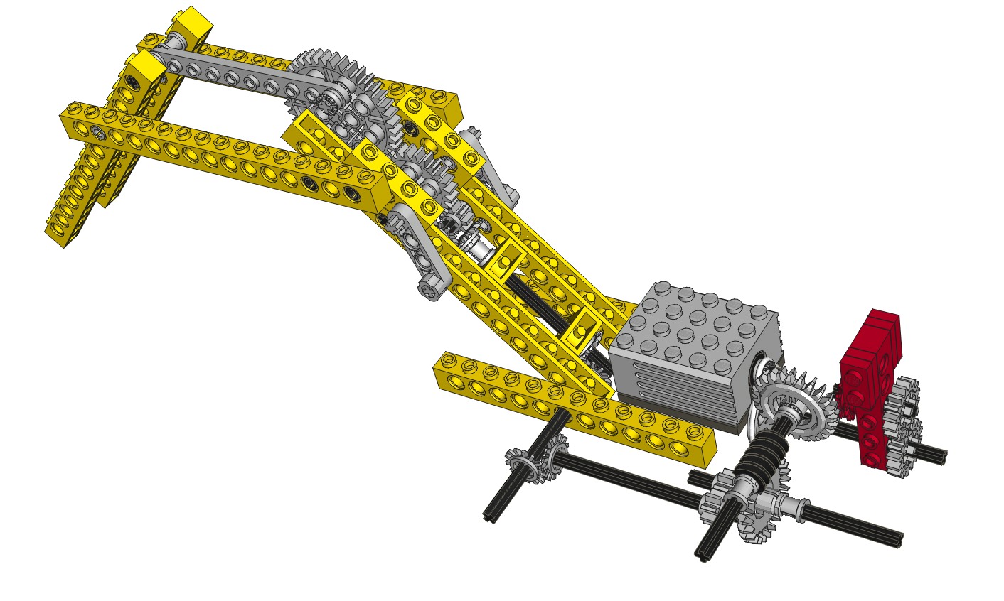
This
robotic
arm
performs the task of lifting 1x2 beams from a chute and
sorting them into color coded bins. It would be many years before
something similar was available using the computerized Mindstorms®
system. This is an excellent example of the complex functions
which could be achieved with a relatively small variety of parts.
The arm is capable of rotating, lifting, and opening the end
effector. There are 3 motorized functions despite the fact that
there are only two motors. The method used to achieve this is
quite clever and is described below.
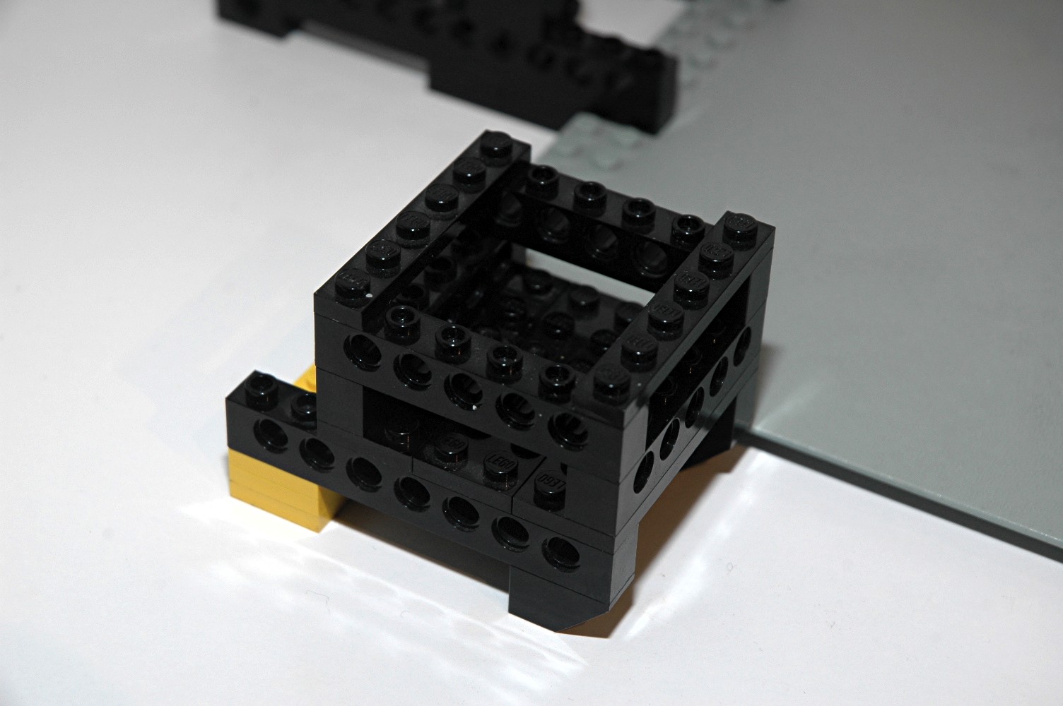
A base plate is used to hold all of the assemblies in the correct
position relative to each other.
|
|
|
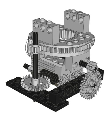
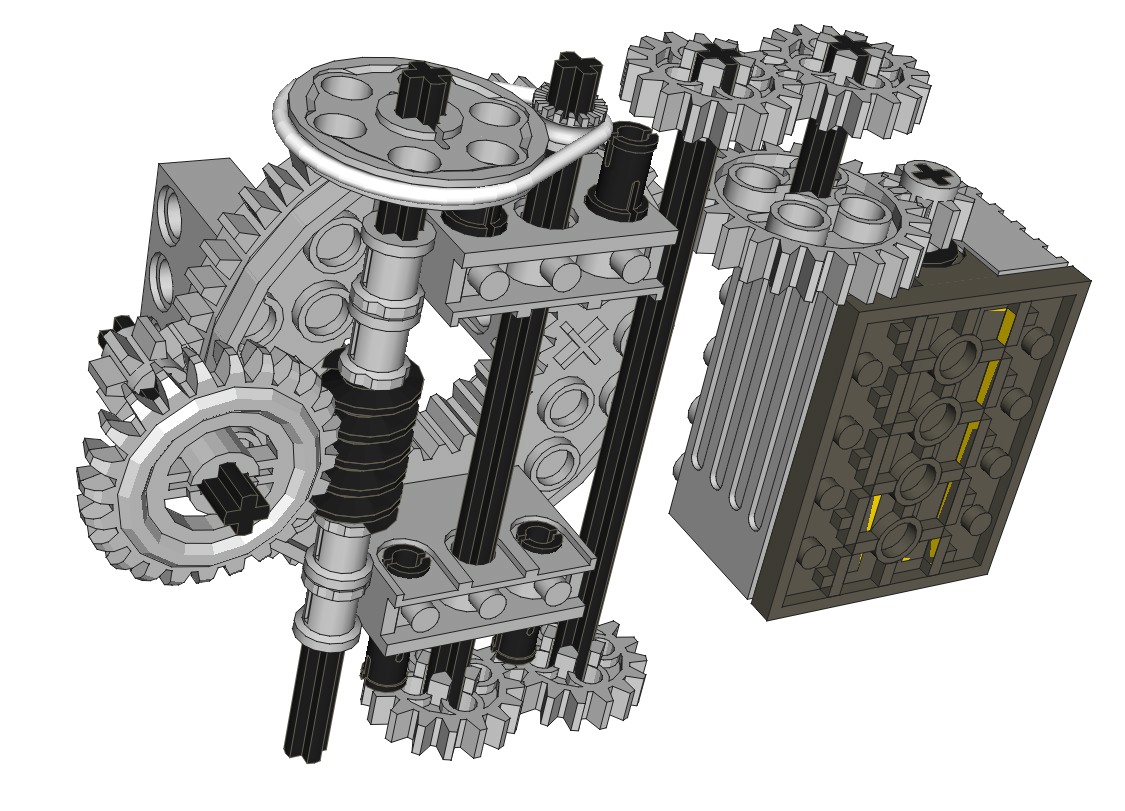
Motorized
Rotating Arm
The arm can be rotated side to side using a motor contained in the
fixed base. The system is supported by the new Technic turntable
which is able to support the unbalanced weight without falling apart.
The motor drives a pulley through a belt (hidden behind the turntable
in the computer image). This axle then drives a set of 8 and 24
tooth spur gears followed by a set of 16 tooth spur gears. Next a
worm gear drives a 24 tooth crown. Finally, an 8 tooth pinion
drives the outer ring gear of the turntable which has 56 teeth.
Final gear reduction is 3:1 x 24:8 x 16:16 x 24:1 x 56:8 = 1512:1.
Based on the motor's loaded rotation
rate of 2000 rpm, the rotation rate of the arm is about 1.3 rpm
with a full 9V charge. The rate shown in the animation is much
faster than scale.
|
Click for an animation of the arm
rotating. |
|
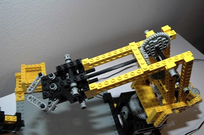
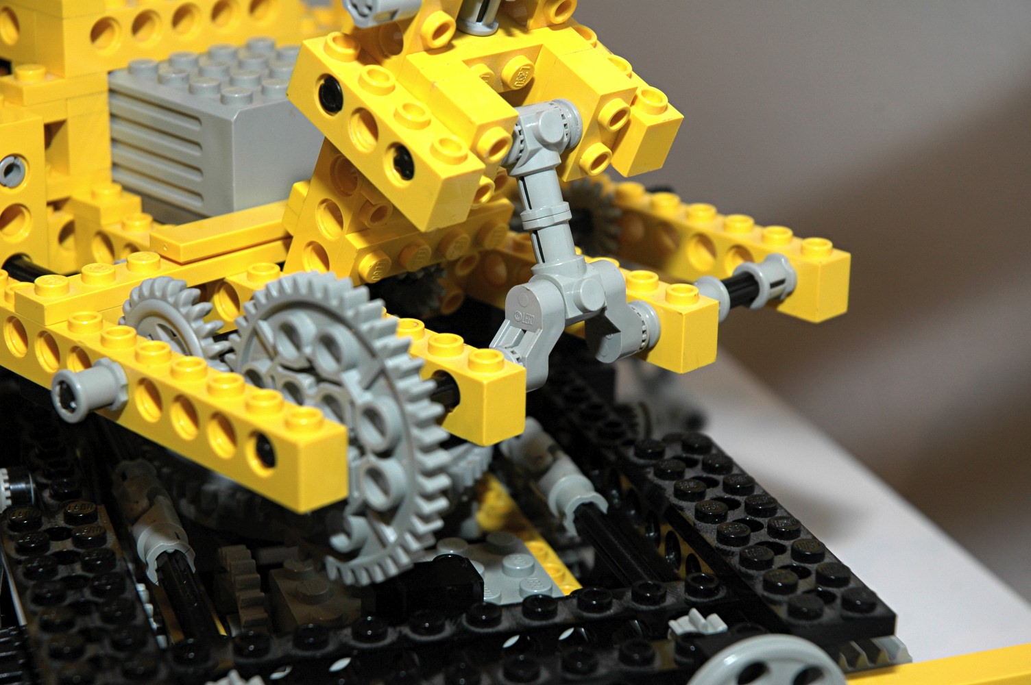
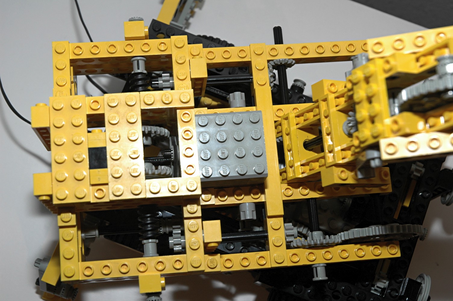
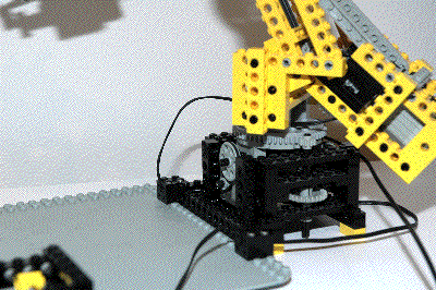
Motorized
Lifting and Grasping End Effector
The motorized lifting and grasping end effector is practically
magic. Both functions are controlled by a single motor mounted in
the back of the arm and used as a counterweight. The color coded
computer image can be used to help explain the workings of the system.
When the arm is in the fully down position, the beams making up the 4
bar linkage are bottomed, which prevents the arm from descending any
further. In this position, the path from the motors to the end
effector is as follows. The motor drives an 8 tooth spur gear
into a 24 tooth spur. Next comes a belt drive through a pair of
pulleys to prevent the motor from stalling. The first blue axle
then drives a 24 tooth crown through a worm gear, preventing
backdriving of the system. A triplet of 3-24 tooth gears
follows. A 24 tooth crown then drives a large 40 tooth spur gear
on the third blue axle. The next major gear reduction happens
through the set of red and green 8 and 40 tooth spurs (more about these
later). This large gear then drives a 24 tooth crown. A
pair of 8 tooth pinions then drive a pair of 16 tooth spur gears which
rotate in opposite directions. Finally, two sets of 14 tooth
bevel gears drive the liftarms which make up the end effector.
Final gear reduction is 24:8 x 3:1 x 24:1 x 24:24 x 24:24 x 40:24 x
40:8 x 24:40 x 8:8 x 16:16 x 14:14 = 1080:1. The fingers can be
opened and closed by reversing the motor.
The lifting of the arm uses the very same gear system. How is
this possible? When the end effector closes on something, either
itself or an item it is grasping, the last blue axle becomes
effectively locked. Remember those red and green gears in the
image? When the last blue axle is locked, relative rotation of
the red and green gears causes the angle between the yellow beams to
change, thereby rotating the 4 bar linkage. Because the 2 long
arms of the 4 bar linkage are different lengths (1 stud difference),
the arm changes shape and lifts. Since this function does not use
the last 4 stages of the gear system, the reduction is 1800:1. It
only takes a rotation of 3 teeth on the red 40 tooth gear to lift the
arm, so total lifting time is about (1800/2000) x (3/40) = 0.00675 min
~ 4 seconds.
The difference between these two types of motion can be seen using a
close study of the animation.
|
Click
for an animation end effector grabbing and lifting.
|
4th
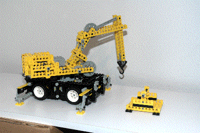
Model: Mobile Crane
|
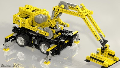
This
motorized
mobile
crane has a host of fascinating functions. It
has outriggers (pictured in light blue), a slewing platform (pictured
in green), and a lifting boom (pictured in yellow) and jib (pictured in
purple).
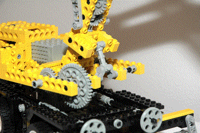
The multiple lifting functions are achieved with a single motor mounted
in the superstucture through a pendular gear which can be seen in red
in the computer images. The other motor drives the slewing motion
and is located in the base. The 4 Model Team wheels are not
steerable.
|
Click to download the LDraw
file of this model.
Model by Eric Albrecht


Click for an animation of
the crane in motion.
|
|
Motorized
Lifting Boom
The boom can be raised and lowered using the upper motor, but only by
driving the motor in a single direction. The red pundulum shown
in the computer image is driven to the right of the motor by the
friction in the axle. This causes it to engage the gear system on
that side.
The motor drives a pulley through a belt and then a set of 16 tooth
spur gears. A pair of 14 tooth bevel gears then mesh with a 24
tooth crown. A worm gear drives the next 24 tooth crown.
Next, an 8 tooth pinion mates with another 24 tooth crown, which
finally drives a 40 tooth spur gear. Final reduction is 617:1.
The final axle drives a pair of the new crankshaft elements.
Revolution of these elements causes an osciallation of the boom up and
down. The boom can only be driven one direction; you can't go
backwards. Instead, you have to wait for it to cycle back around
the where it started. You can see this clearly in the animation.
|

Click for an animation of
the boom lifting.
|
|
Motorized
Lifting Jib
The jib can be raised and lowered using the upper motor, but only by
driving the motor in a single direction. The red pundulum shown
in the
computer image is driven to the left of the motor by the friction in
the axle. This causes it to engage the gear system on that side.
The motor drives a pulley through a belt and then a set of 16 tooth
spur gears. A pair of 14 tooth bevel gears then mesh with a 24
tooth
crown. A worm gear drives the next 24 tooth crown. Next
come a set of 8 tooth pinions followed by a set of 14 tooth bevel
gears. After the bevel gears, the axle passes through the axis of
rotation of the boom. A pair of 14 tooth bevel gears make a 90
degree turn and are followed by another pair. Finally come an 8,
a 24, and a 40 tooth spur gear. Final reduction is 617:1, just
like the boom.
The 40 tooth gear has a link attached to one of the off-center pin
holes. Revolution of the gear causes an osciallation of the jib
up and
down. The jib can only be driven one direction; you can't go
backwards. Instead, you have to wait for it to cycle back around
the
where it started. You can see this clearly in the animation. |
Click for an animation of
the jib lifting.
|
|
Motorized
Slewing Superstructure
The entire superstructure slews on one of the new turntables which is
able to support the unbalanced weight without falling apart. The
motor for this function is located in the base.
The motor drives a set of 8 and 24 tooth spur gears followed by two
pairs of 16 tooth spurs. A belt comes next, driven by a pair of
pulleys. Then a worm gear drives a 24 tooth crown. Finally,
an 8 tooth pinion drives the outer ring gear of the turntable which has
56 teeth. Final gear reduction is 24:8 x 16:16 x 16:16 x 3:1 x
24:1 x 56:8 = 1512:1.
Note that, unlike the animation, the model can not rotate 360 degrees
an infinite number of times. Since the wires pass up through the
turntable they will become twisted if it rotates too far.
|

Click for an animation of
the crane slewing.
|
|
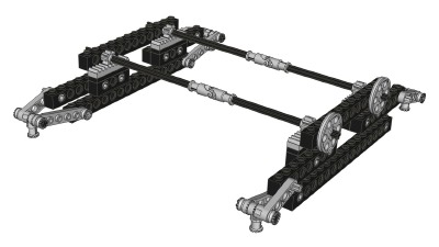
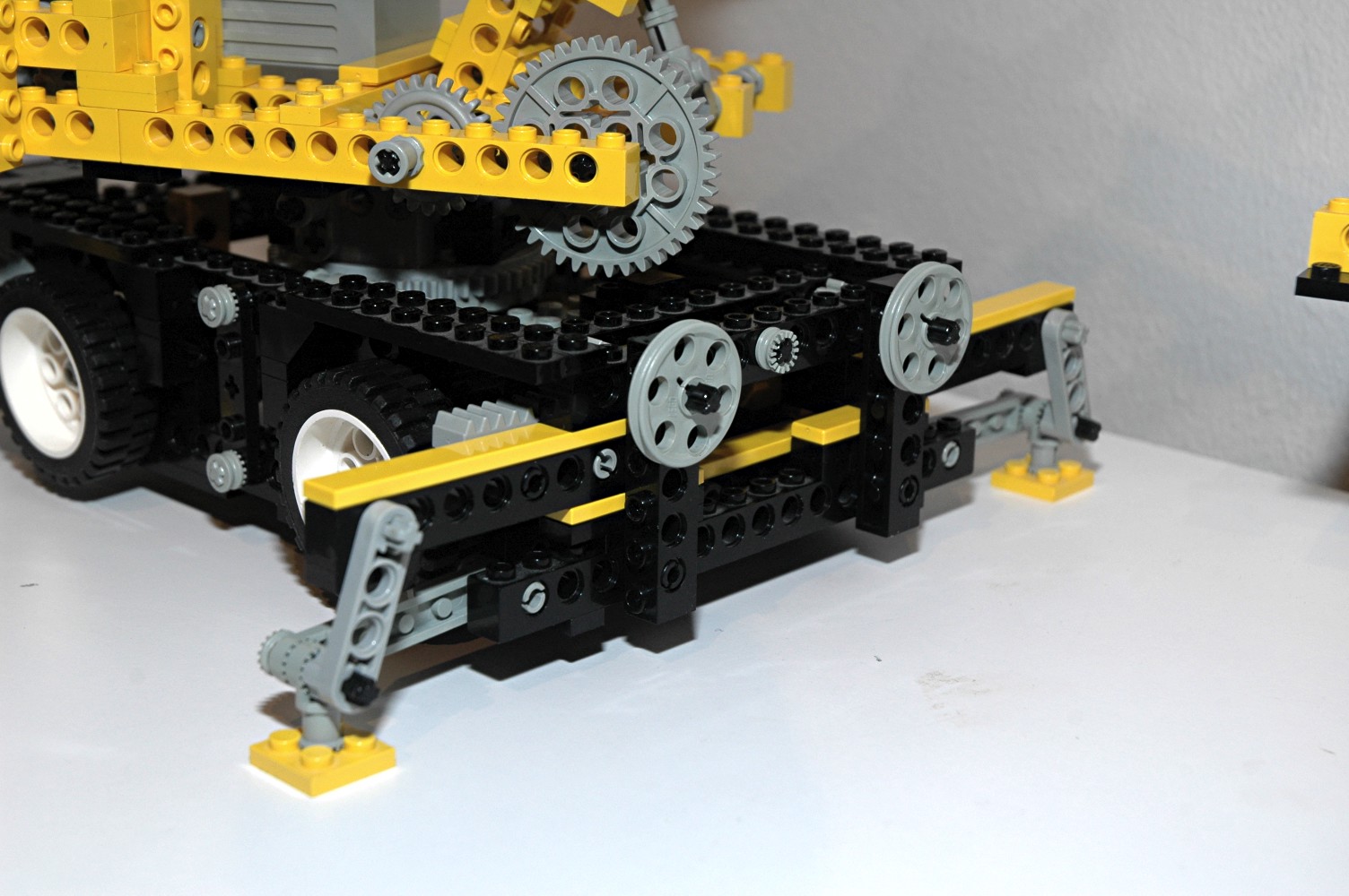
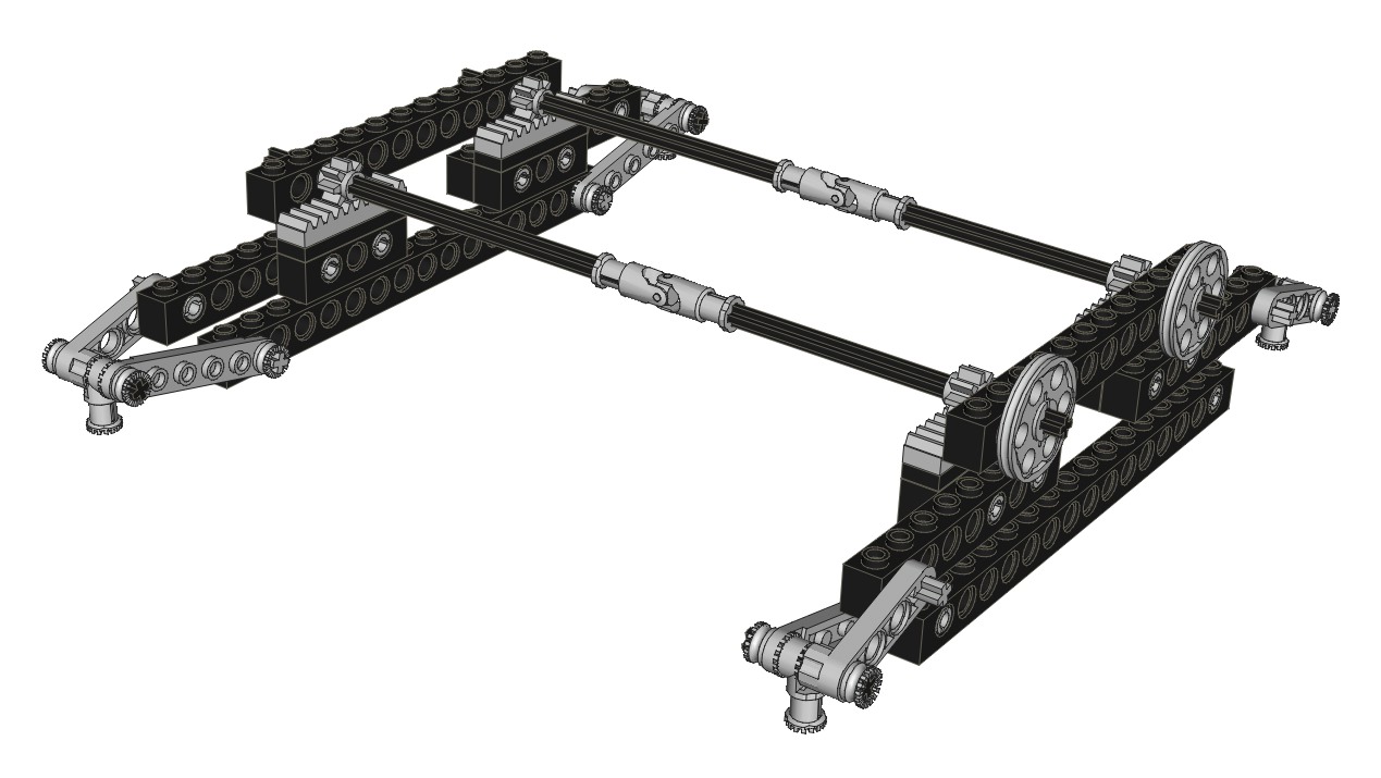
Outriggers
Four outriggers are located at the corners for stability. They
translate outward on tracks made from tiles via a rack and pinion
system as shown in the computer image. As the outriggers reach
their most outboard position, the attached liftarms become almost
vertical, supporting the weight of the crane without backdriving.
Due to the geometry of the system, deployment of the outriggers
actually lifts the wheels slightly off the ground. The outrigger
arms are prevented from rotating inside the body by tightly placed
tiles about and below.
|

Click for an animation of
the outriggers deploying.
|


