Tamiya Flakpanzer Gepard Project
Page 5: Building the Turret
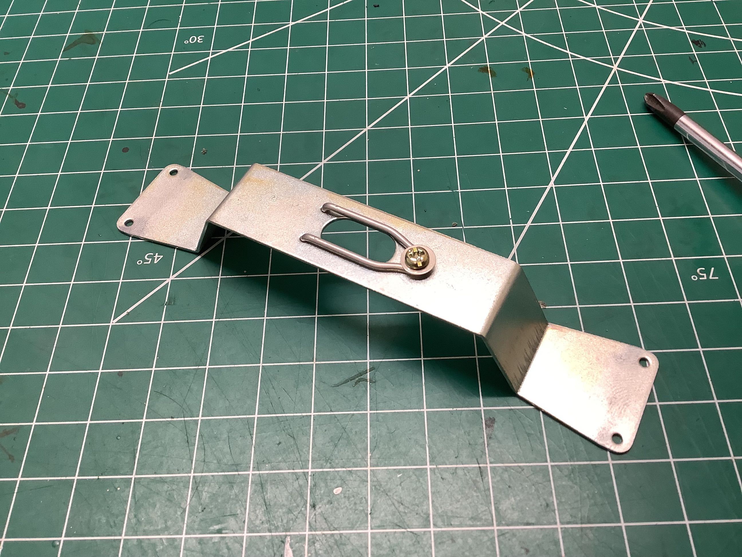
The bracket shown on the left serves as the mounting point and rotation
axis for the turret. The bottom of the turret has a protrusion
which fits into the slot and then rotates 1/6 turn (hex) to be retained
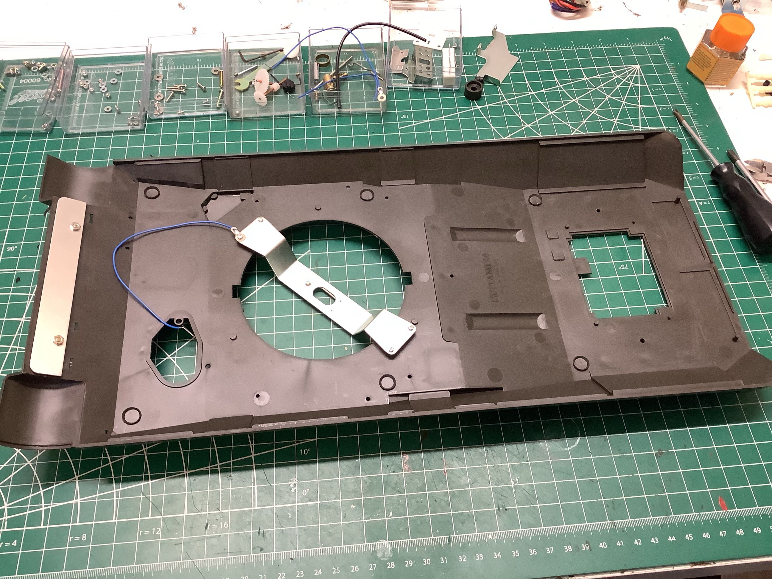
by the spring clip. This bracket also serves as a grounding point
for the turret electrical system. The picture on the right shows
it mounted to the underside of the hull along with the blue ground wire.
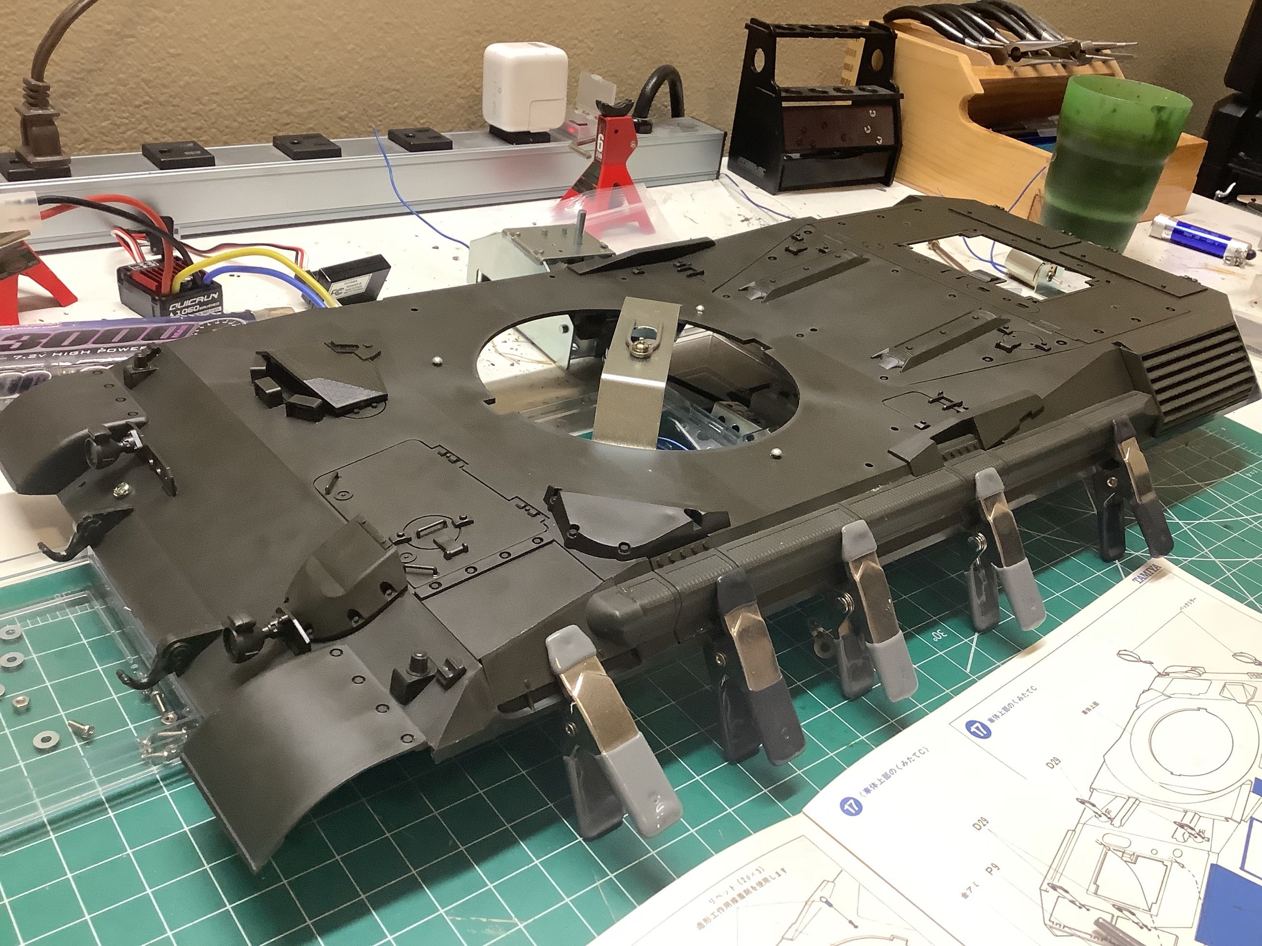
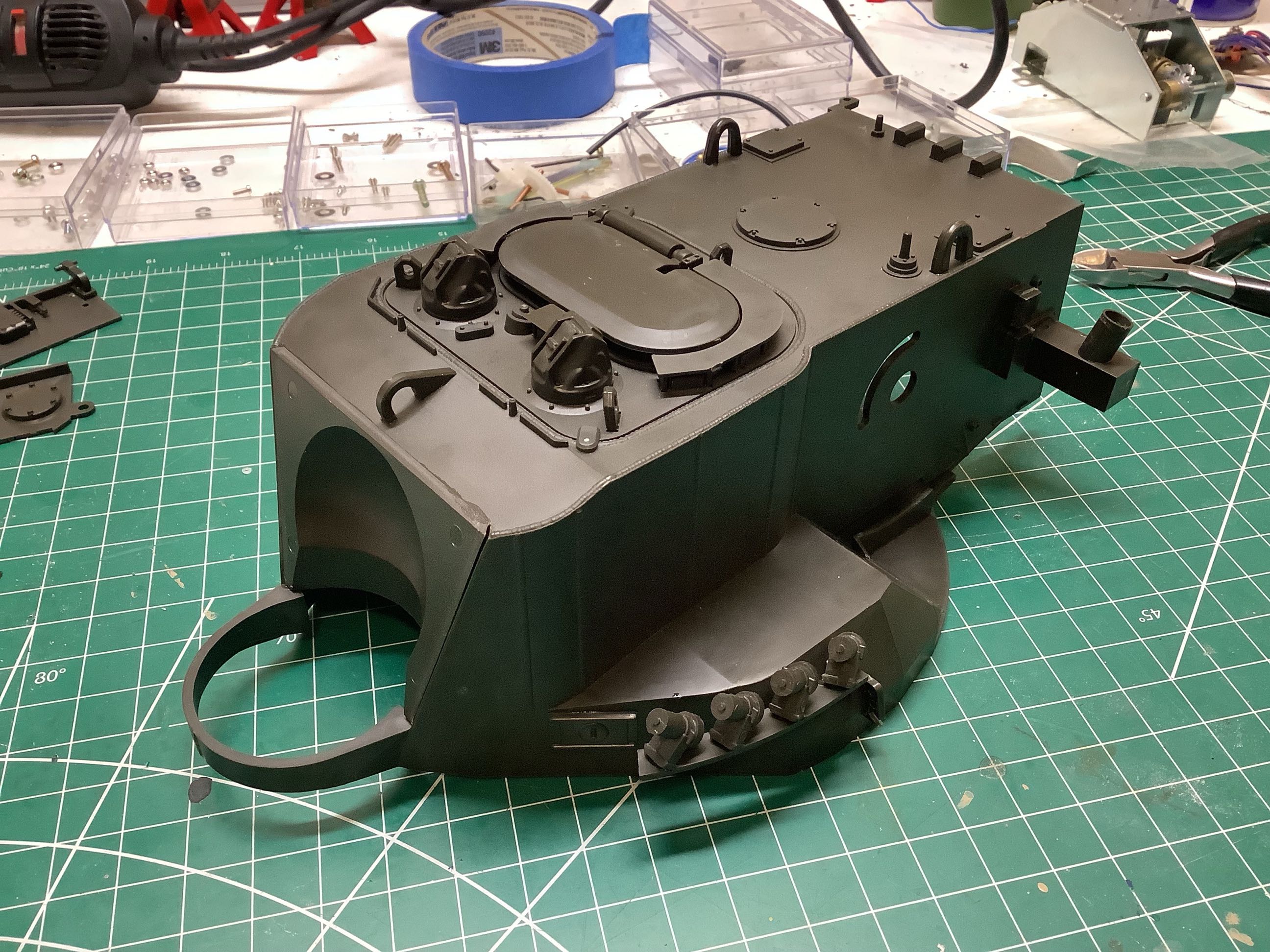
Here I've attached the large number of detail parts to the top of the
hull. The real Gepard has a small diesel engine installed in the
front left of the hull which is used to run generators to drive the
turret traverse, gun elevation, and radar systems. The channel you
see running along the left side is the exhaust system for that engine
which vents through the back. The large hatch on the front left is
for accessing this engine. The much larger hatch on the back is
for accessing the main drive engine. The hatch on the front right
is for the driver and contains the driver's periscopes as well as an
extra armored panel over the hatch. The model uses this hatch to
access the main power switch.
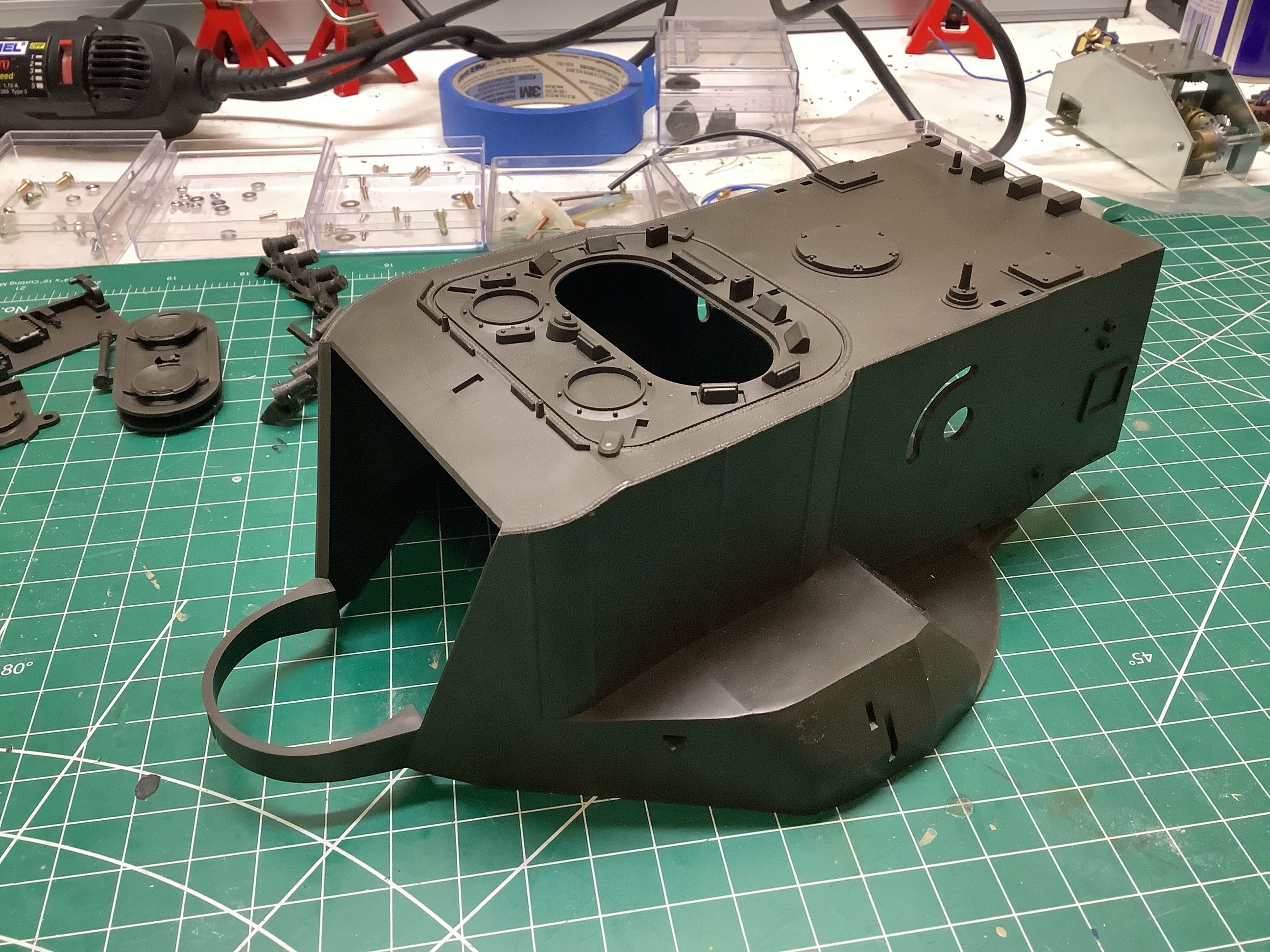
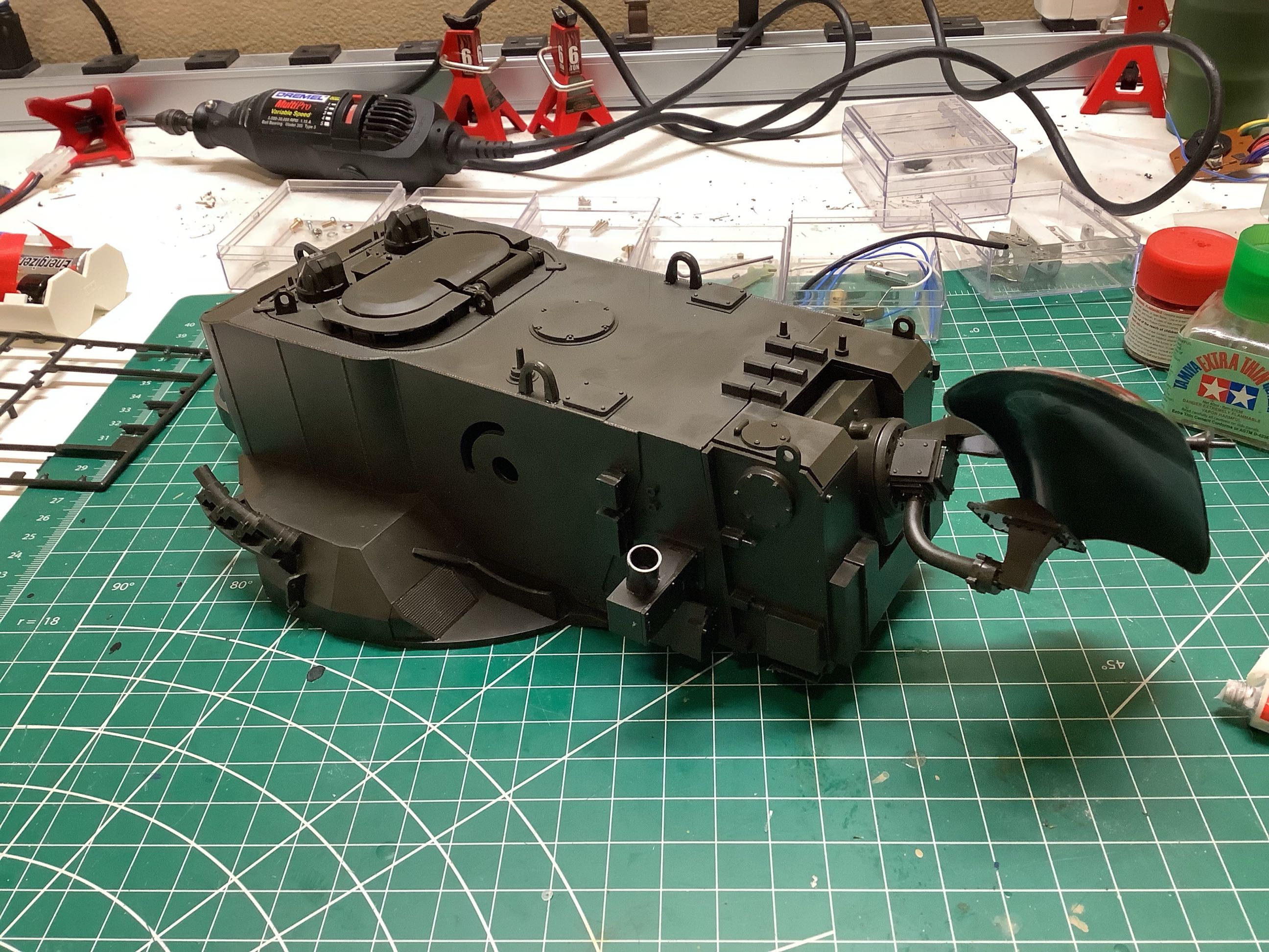
These pictures show the buildup of detail parts on the main turret
housing. The picture on the left is a single molded part. On
the right I've added smoke canisters, antenna supports, lift points,
hatches, and periscopes. The hatch even has a clever working latch
system. Everything is extremely detailed in typical Tamiya
quality, though this is even more impressive given the year of
release. Zoom in on the left picture and look at the weld beads
and bolt heads.
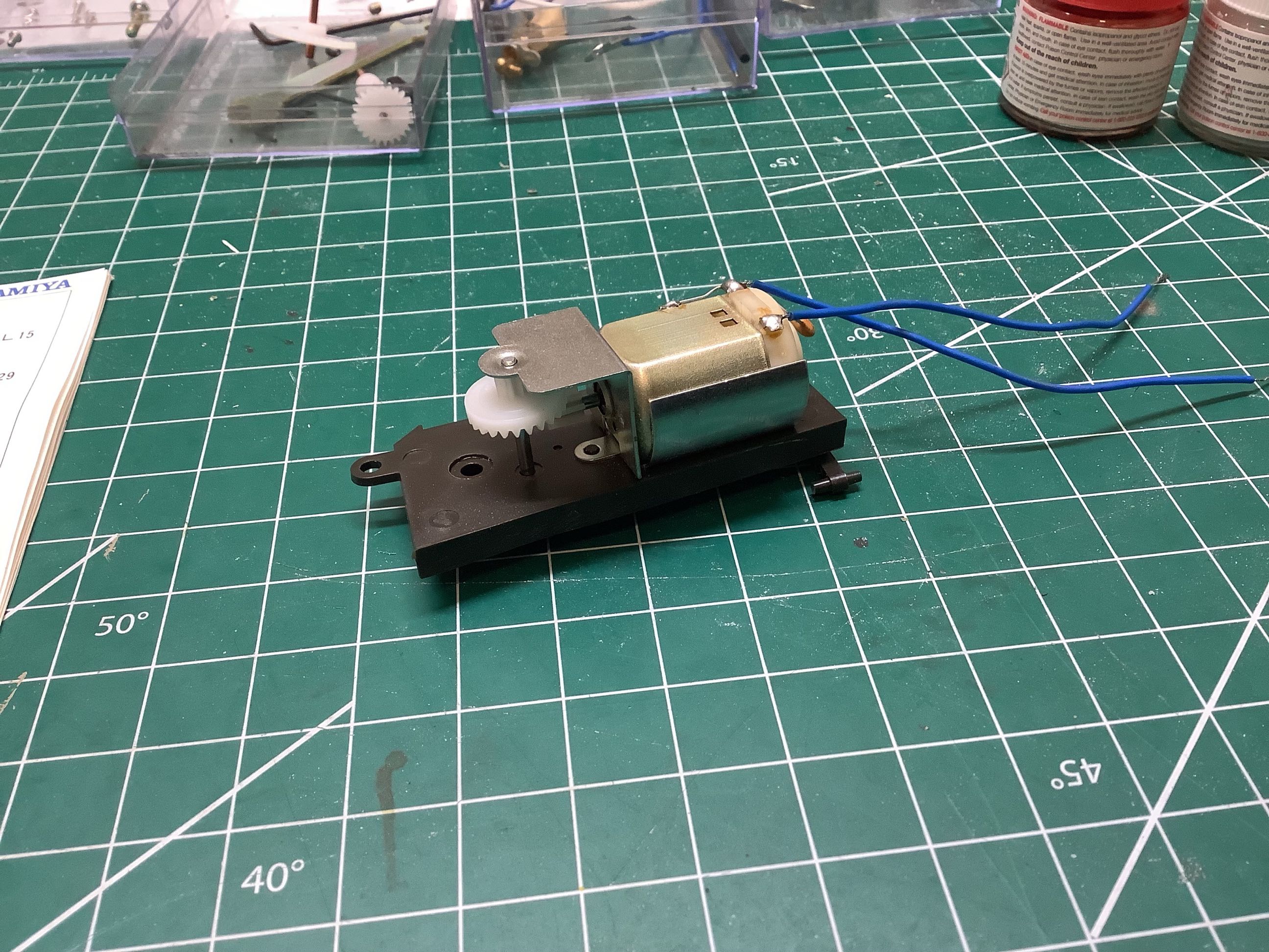
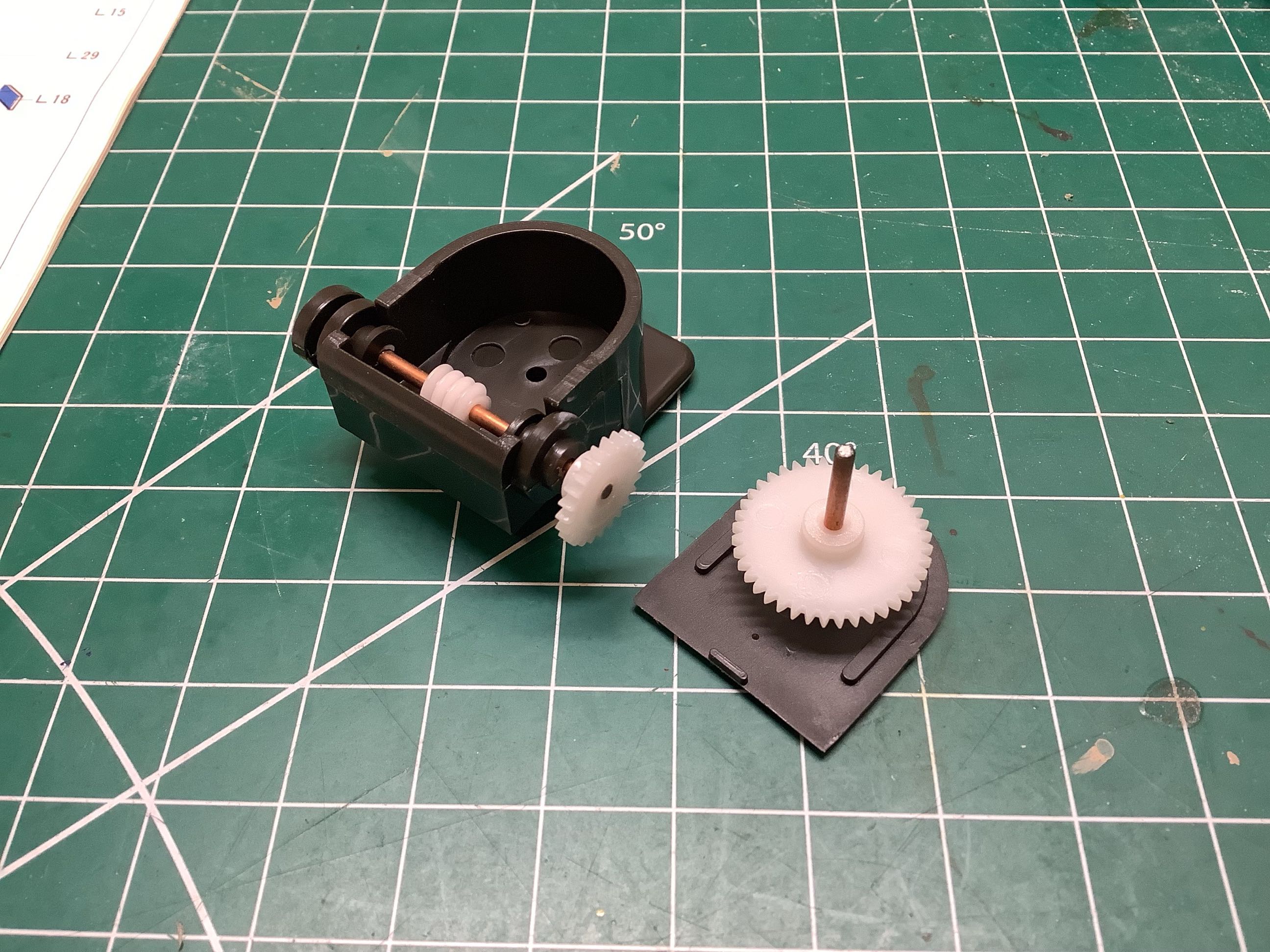
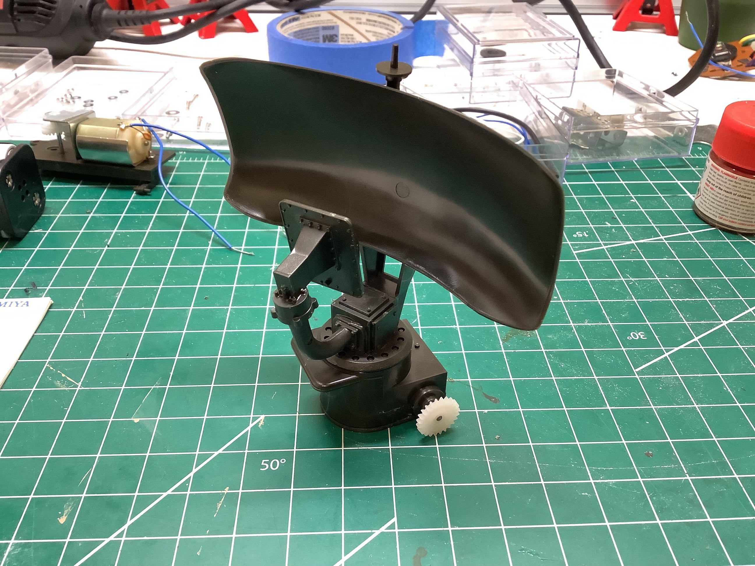
This is the motor used to drive the rear mounted search radar. It
has 3 stages of reduction: one at the motor pinion, another at a right
angle into the radar housing, and a final large reduction using a worm
gear. The radar dish itself is only pressed lightly onto the final
shaft so it can slip if it becomes blocked. This motor was
intended to run on only 3V from a pair of C batteries, but even so it
rotates very quickly. At first I thought it was way too fast for
scale, but then I saw some videos of the real thing which rotates at
about 60 rpm.
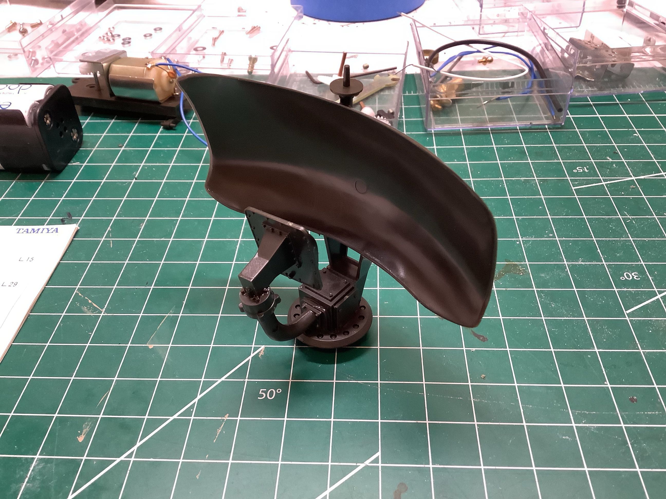
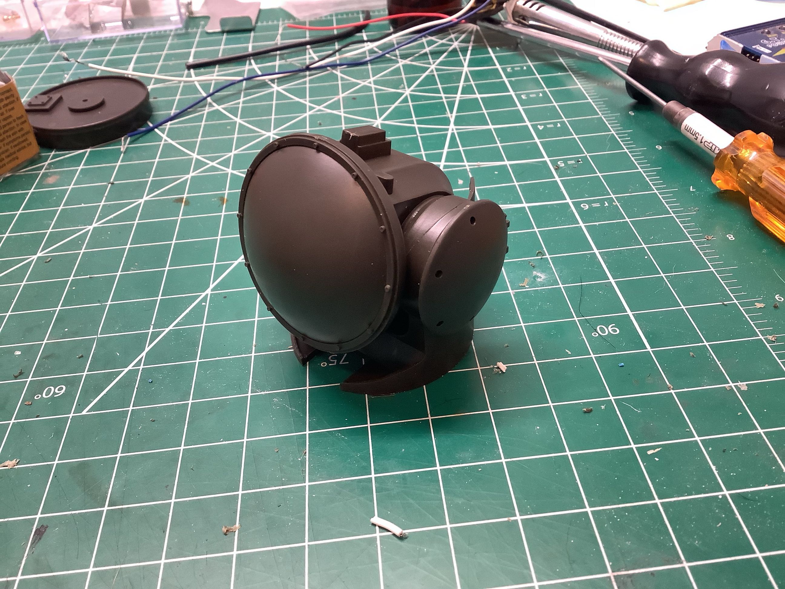
Here is the MPDR-12 Doppler search radar which is used to acquire
targets. It may look like only a couple of parts, but there are 13
parts here even before the mechanism for turning the radar.
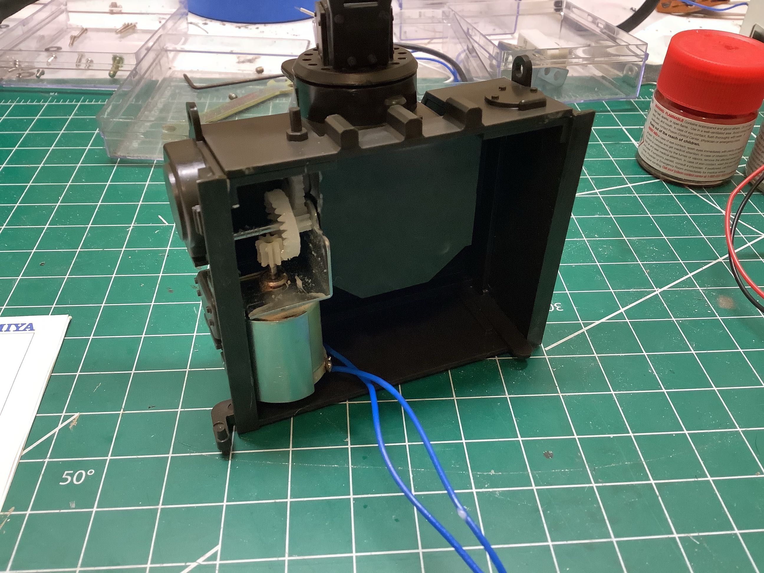
The picture on the left shown how the motor drive system for the search
radar is installed into the hatch on the rear of the turret. On
the right you can see the hatch installed onto the turret. Note
that the radar can fold down to lower the profile of the vehicle for
transport. It raises when in use. This rotation is purely
manual in the model; no motorization. This rear hatch is hinged so
it can be opened to maintain the mechanism.
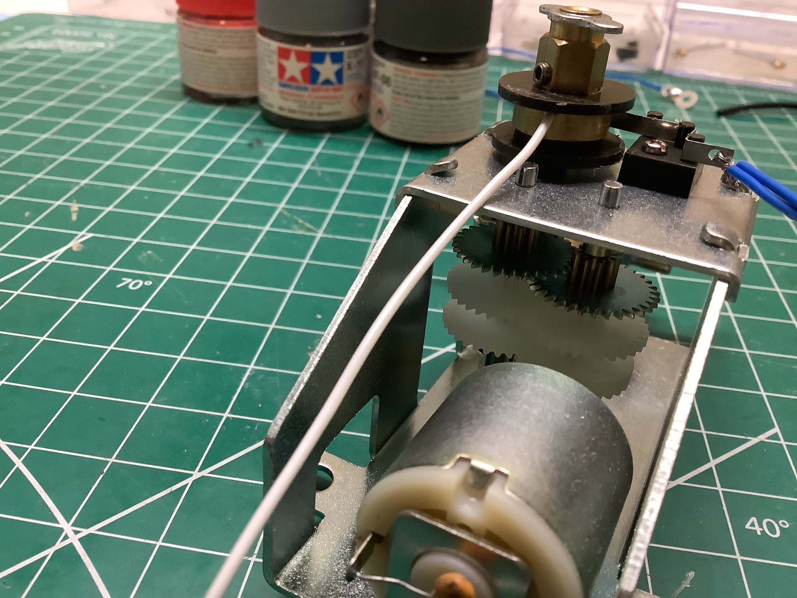
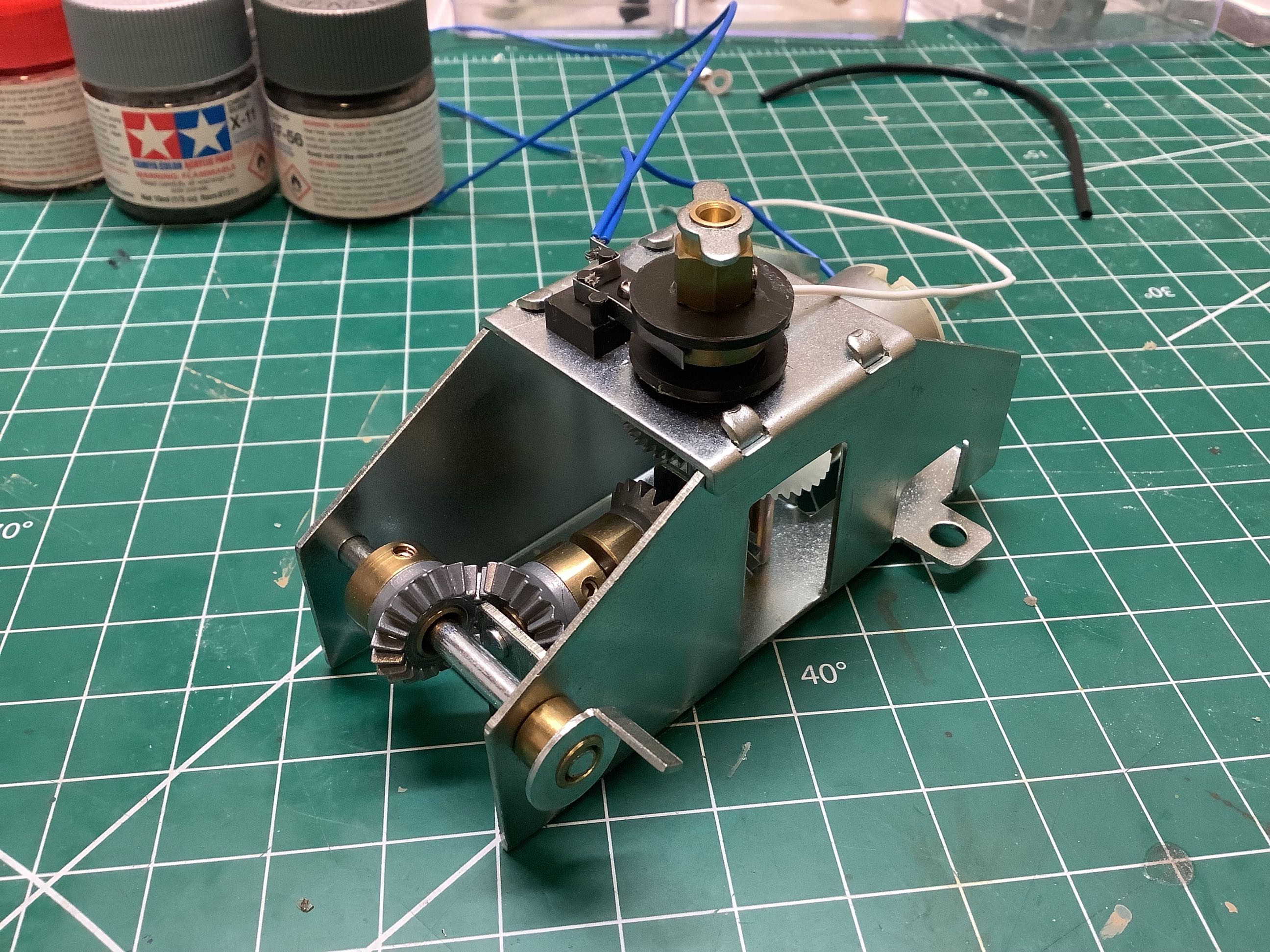
This little brush system is intended to allow power to pass from the
hull to the turret without tangling any wires, thus allowing 360 degree
rotation. In practice, it didn't quite work out. The white
wire has to be sandwiched between a plastic shaft and a metal collar,
but there is no slot for the wire so it ends up getting pinched very
tightly. After only a short while, my wire severed. It can
never be reattached because the collar can't be removed without
destroying the part. Luckily, I was already planning to use a
speed controlled electrical system for the turret anyway or I would have
been very upset about this failure. The picture on the right
shows the many stages of reduction between the motor and the
output. The initial stages are plastic because the torque is low,
but the final stages are metal.
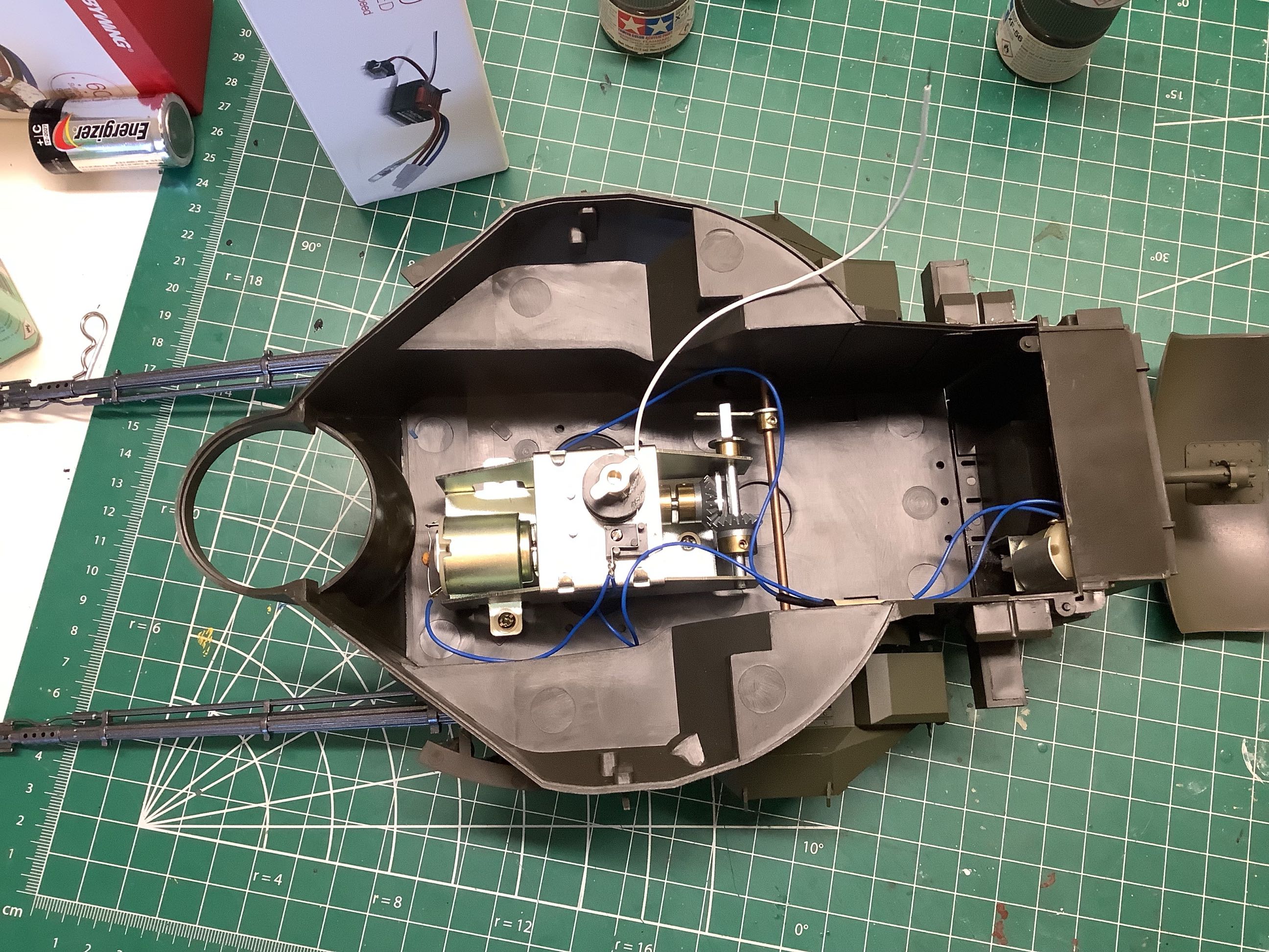
The picture on the left shows the turret traverse mechanism. The
motor
is protruding at the upper right and it drives the crank at the upper
center. At the same time, it drives the crank at the lower left at
a
1:1 rotation with the turret. The little tab on the crank serves
to lift
the barrels up as the turret rotates. The barrel elevation cannot
be
controlled independently. The picture on the right shows this
system installed into the turret. The turret and radar are wired
together on the same circuit so they move together, thus requiring only 3
channels to operate the model.
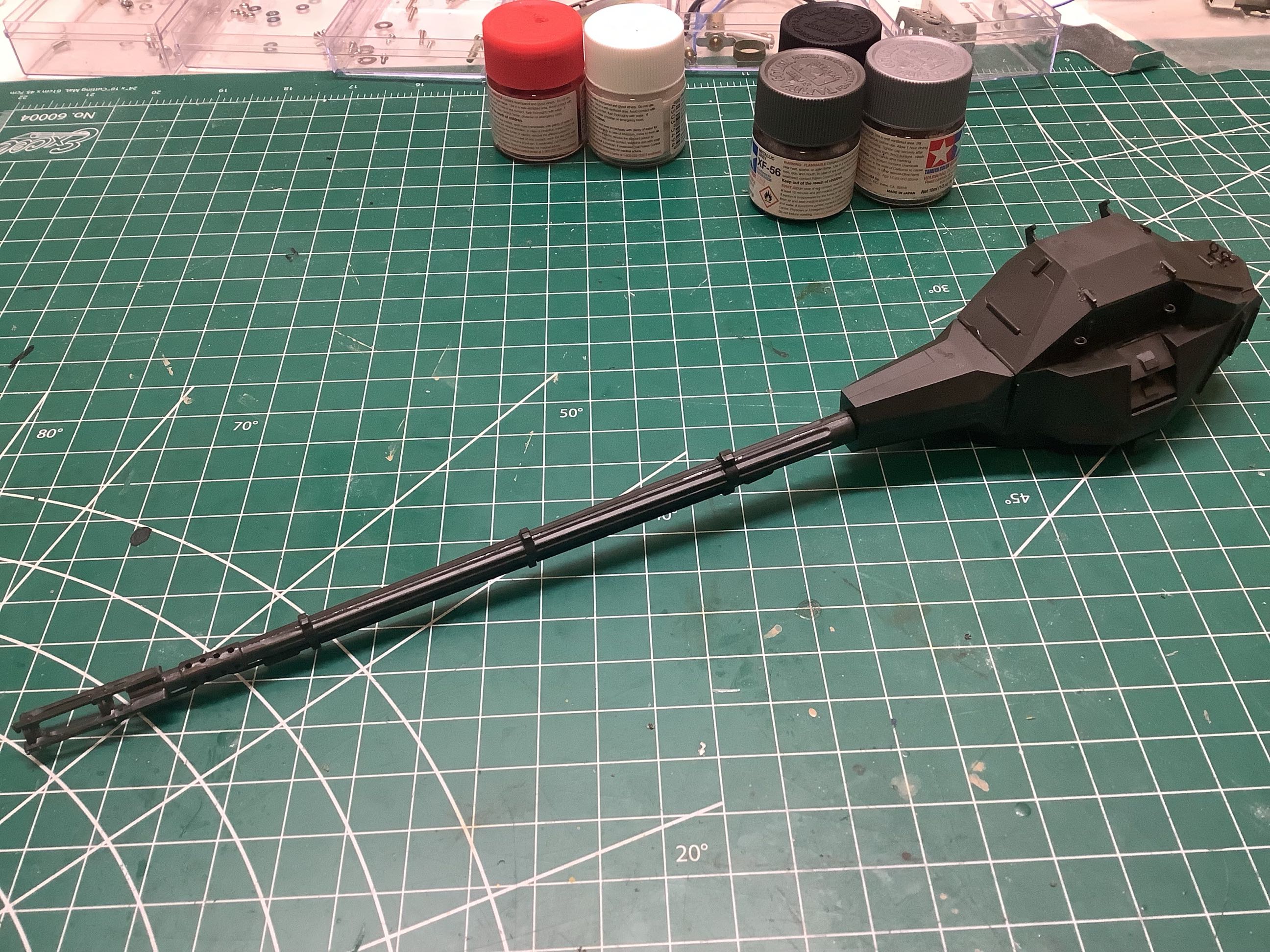
The picture on the left is one of the Oerlikon 35mm cannons which
consists of 22 parts, some of them very tiny. The guns press onto
the elevation shaft with a friction fit rubber washer which makes them a
bit wobbly but easy to adjust and/or remove. The picture on the
left is the tracking radar which is gimballed on two axes (no
motorization, manual elevation and azimuth).
©2021 Eric Albrecht