Tamiya Flakpanzer Gepard Project
Page 4: Building the Gearbox
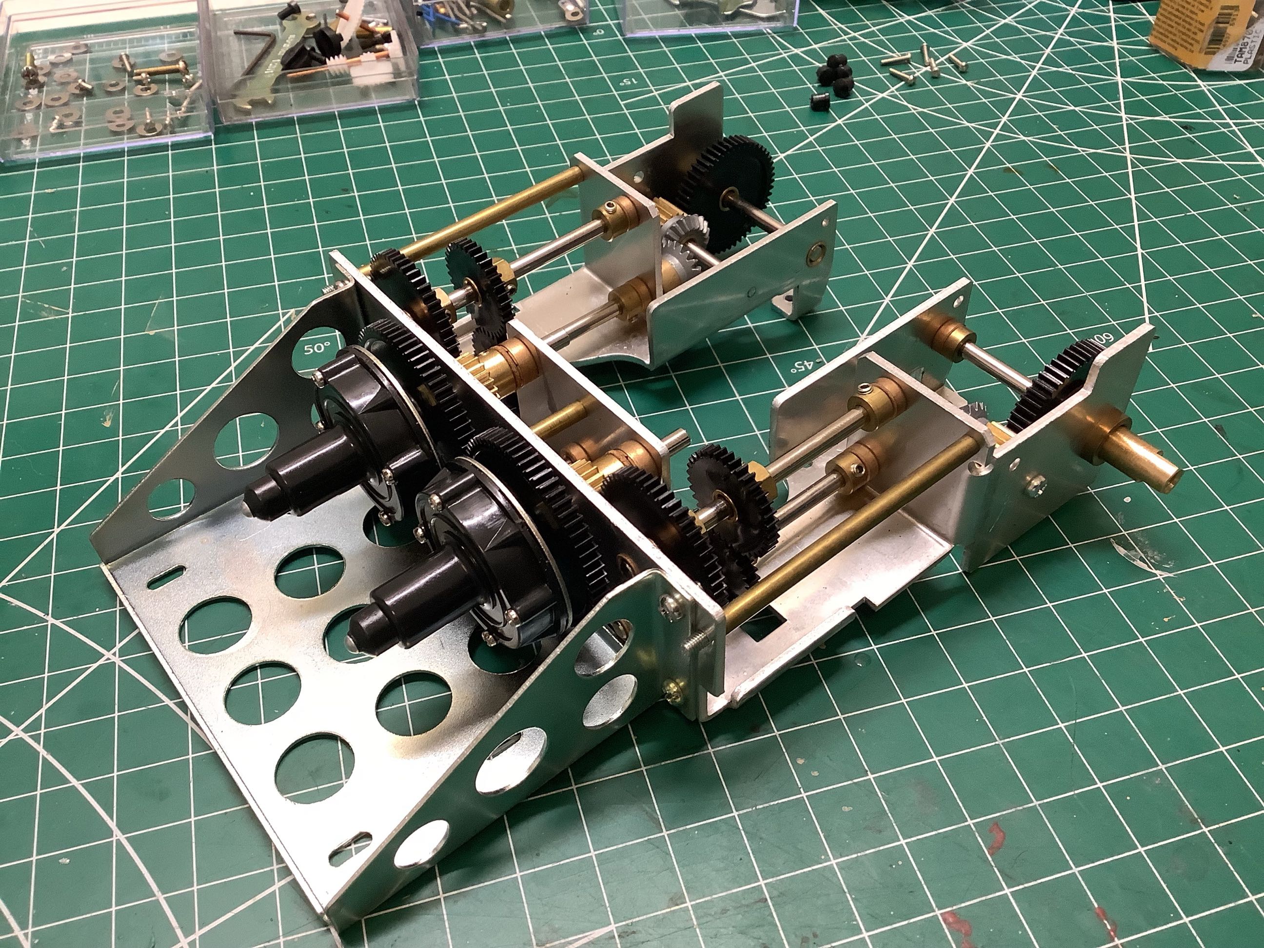
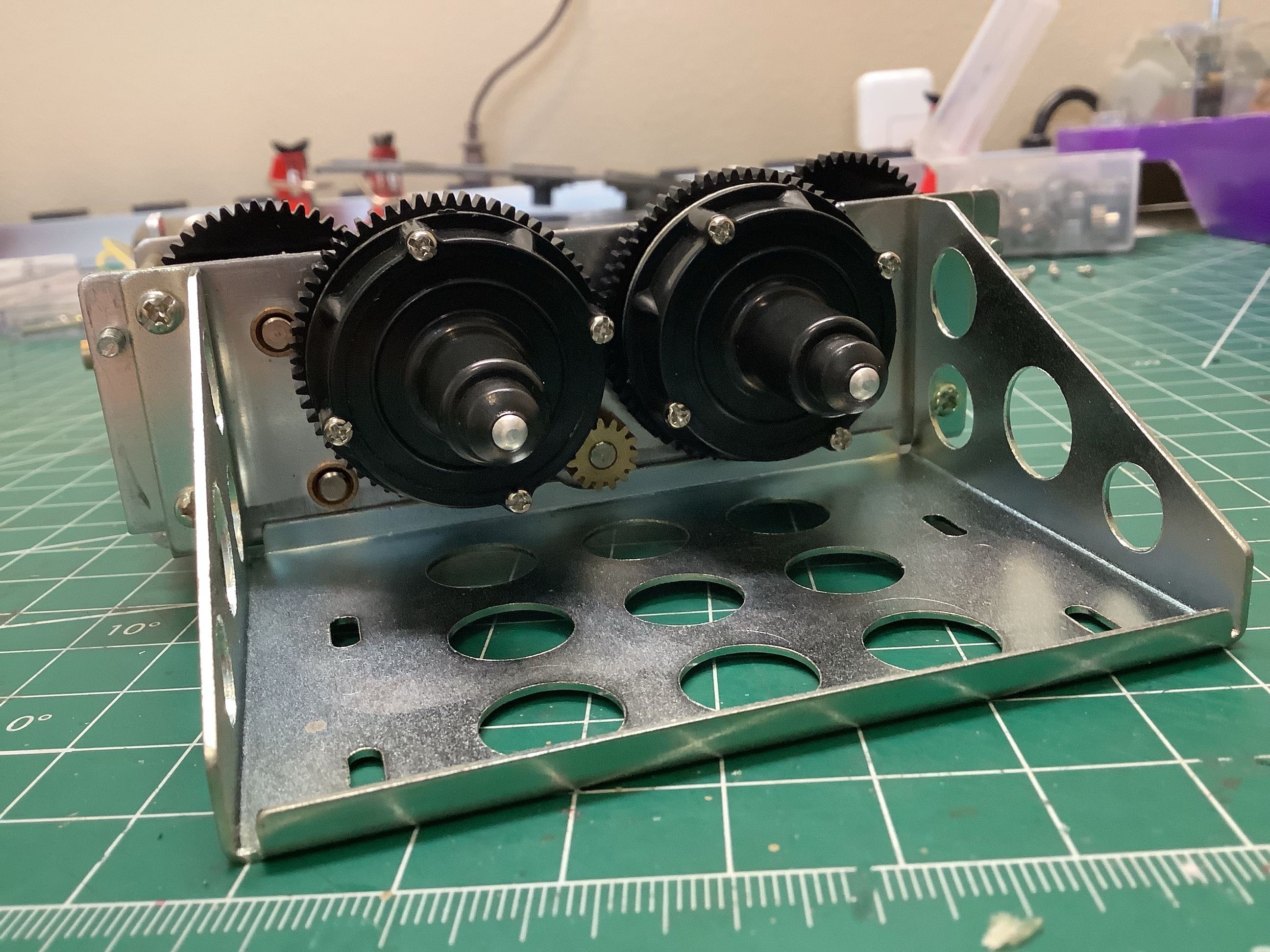
The gearbox comes out of the packaging already built as shown.
There are several interesting things to note. The right and left
side gear trains are mirrored but otherwise identical. The two
black spur gears mate together making them rotate in opposite
directions. The gears range from molded plastic to sintered metal
to machined brass. Most of the gear pairs match brass to plastic
with the exception of the bevel gears which are both metal (I hesitate
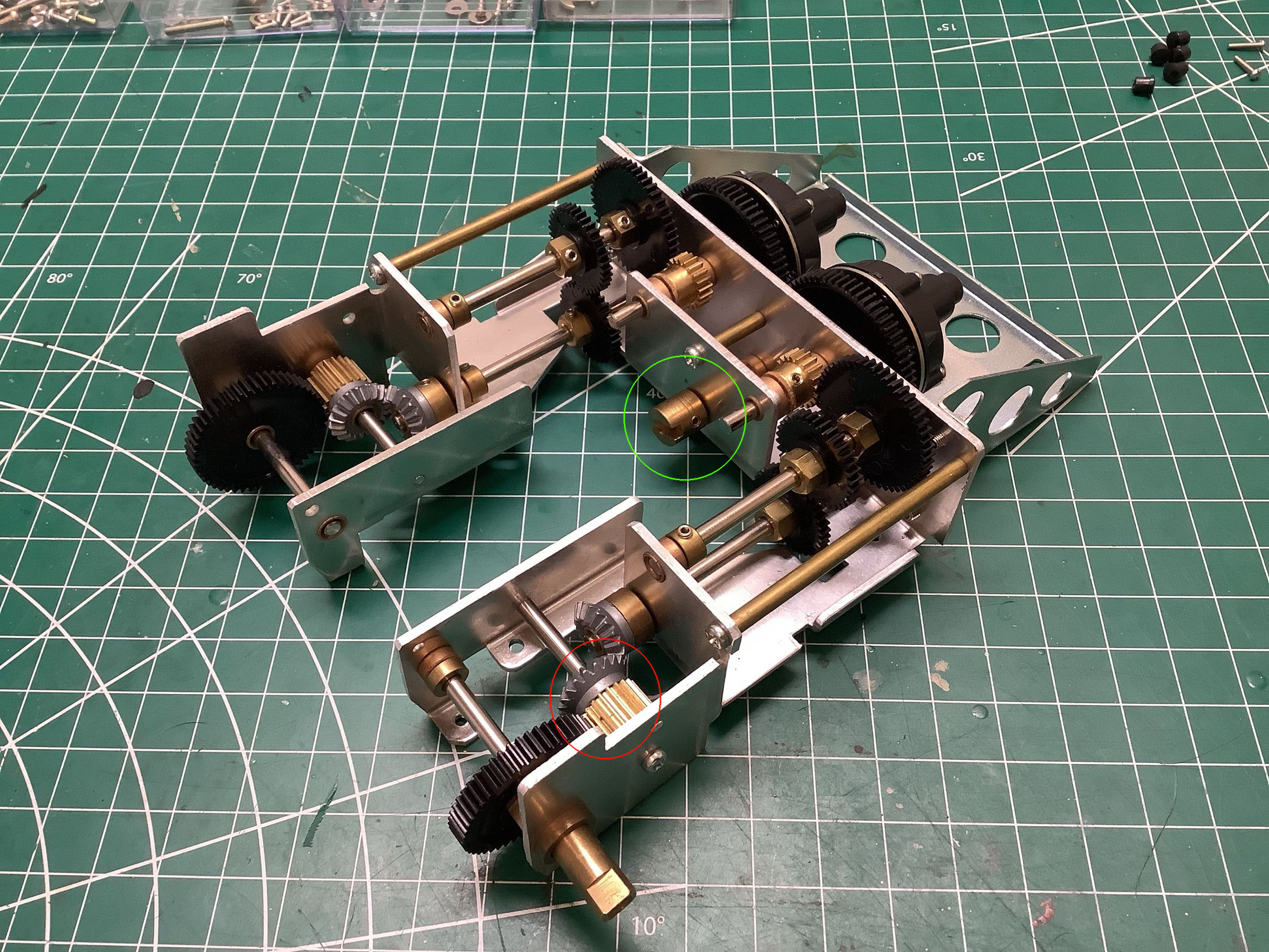
to use the word steel). The motor input location can be seen in
the right hand picture circled in green. There are no bearings in
this gearbox. In general, the gears are locked to the shafts with
set screws so that the shafts rotate with the gears. The shafts
fit into brass bushings pressed into the sheet metal housing. All
of these sliding joints need to be lightly lubricated for the gearbox to
run smoothly. It is not tolerant of dirt and grit getting
into it. Axial motion of the shafts is prevented with brass
collars and cork washers. There are five total gear stages which
progress as described below:
- Pinion/Spur = 15:64
- Stage 1 = 15:50
- Stage 2 = 36:36
- Stage 3 = 20:20
- Stage 4 = 20:50
- Overall = 35.6:1
Note that two of the gear stages are 1:1 and therefore provide no
reduction. The overall ratio of 35.6:1 is not very much reduction,
but keep in mind that this was originally intended to run on 6V. I
did have one repeating problem with this gearbox. The two gears
circled in red on the right connect the 3rd and 4th gear stages and are
meant to rotate together but there is no mechanical connection between
them. They rely on the friction of a light press fit to
work. I found that it didn't take much resistance for this joint
to begin slipping which effectively stops the tank. I separated
them, roughed up the mating surfaces, then pressed them back
together. That seemed to do the job and I've had no further
problems.
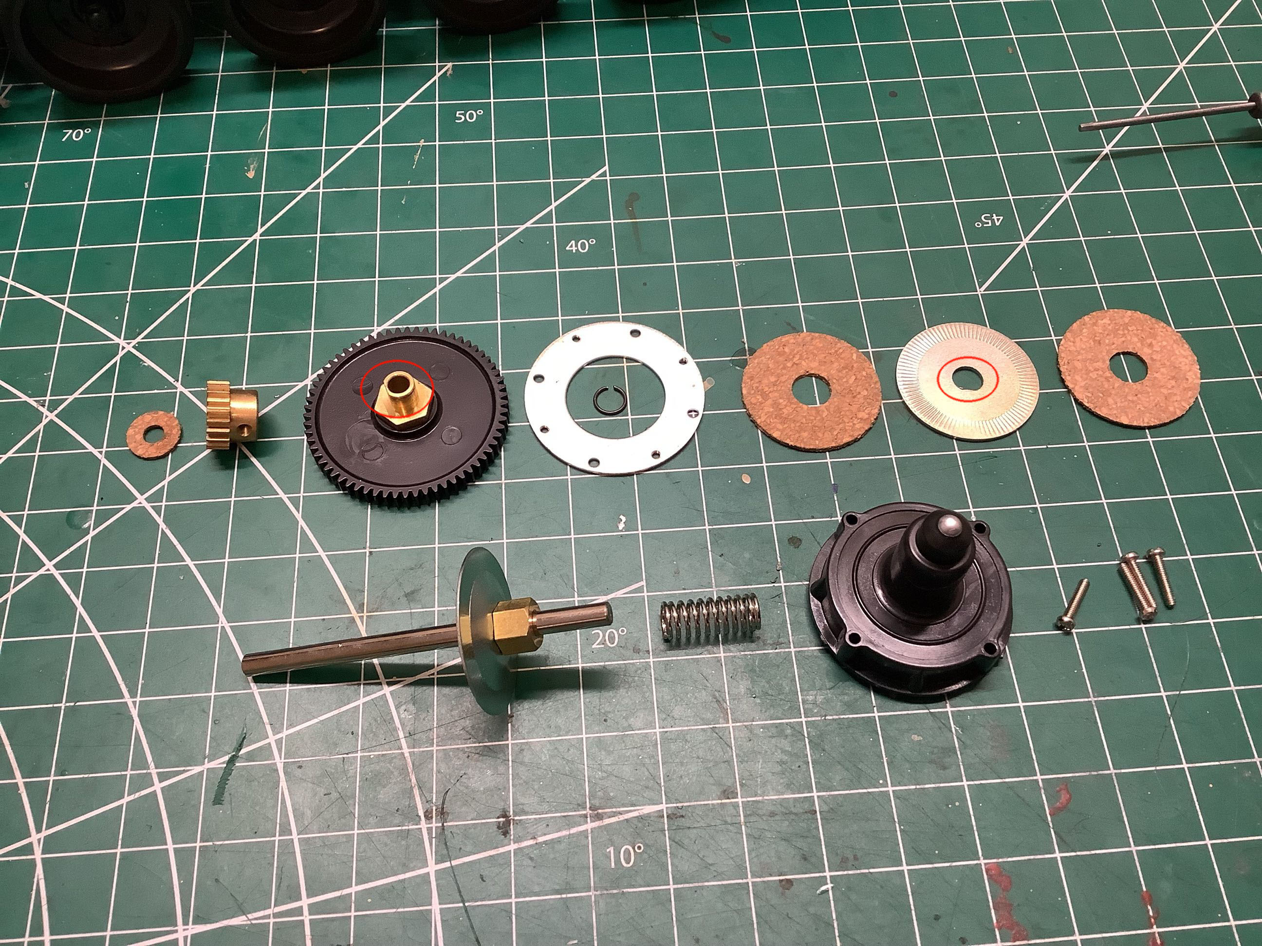
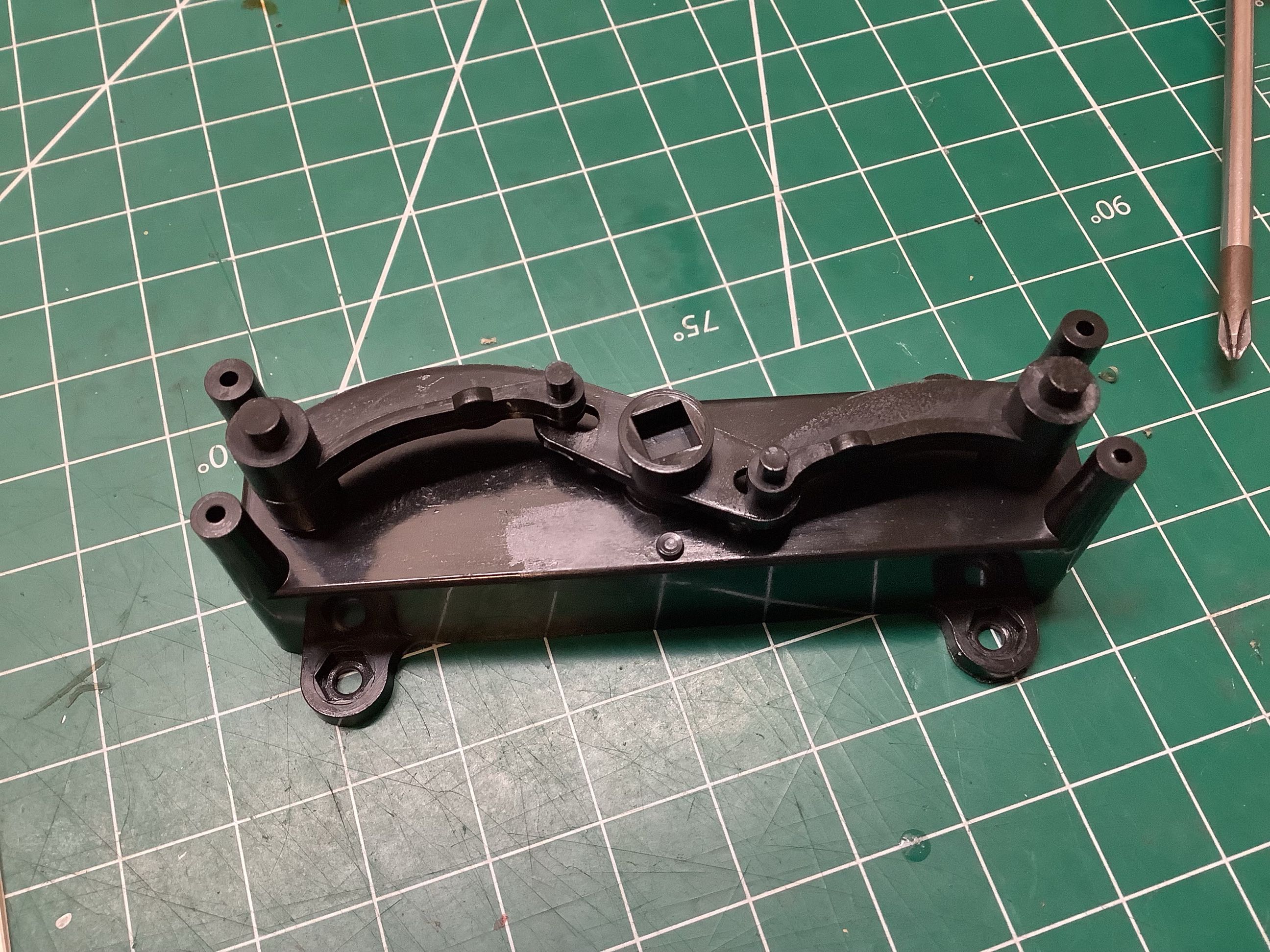
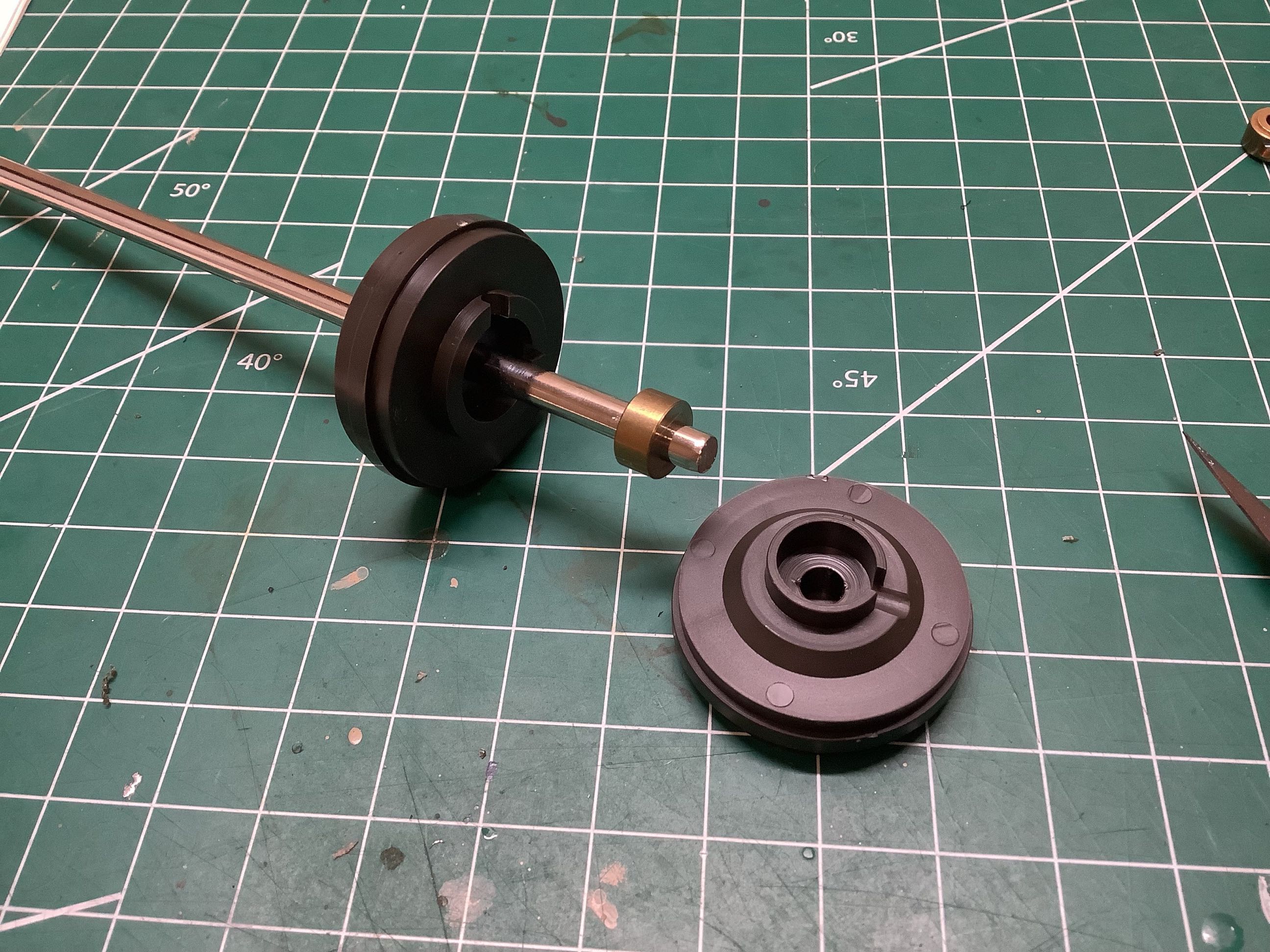
I didn't tear down the entire gearbox, but I was compelled to take apart
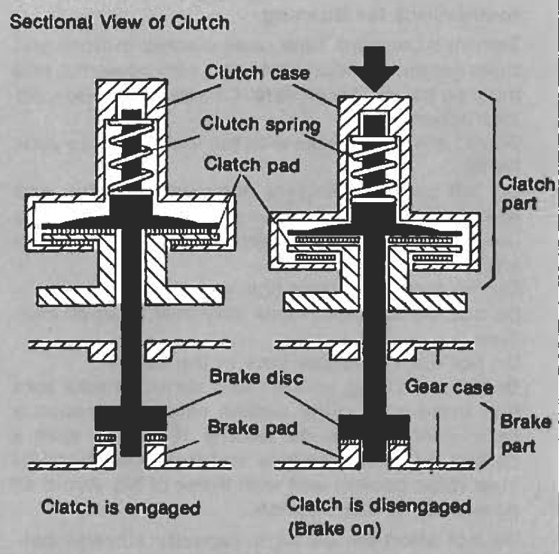
the clutch and see how it worked. An exploded view of the parts
is shown on the left and a cross section from the Leopard A4 manual
(which uses the same gearbox) is shown on the right. The large
black gear is the spur gear which is driven by the motor directly from
the pinion so it is always spinning. I've circled the areas which
are the key to the whole thing working. You may have to zoom in on
the picture on the left to see the flat spot on the brass collar and
on the metal disc that I'll call the rotor. The flat spot makes
these rotate together. The rotor has radial grooves on it to help
it grip the cork stators. When the spring is engaged (which is the
default), the rotor is locked between the cork stators which are in
turn locked to the annular metal plates on either side. Pressing
the metal button at the end of the clutch housing compresses the spring
as the housing slides aft. This releases the clutch by
disconnecting the spur gear from the shaft. This is a really
clever system which allows a single motor to drive both tracks while
disengaging either side with the clutch for steering. Note that
the clutch can be partially slipped which allows gentle turning.
Zero turn radius (tracks turning in opposite direction) is not possible
with this system though. One last little detail relates to the
brake shown on the bottom right. Simply releasing one side would
disconnect that track from the motor, but it would still be able to
freewheel which would not be enough to allow for sharp turning.
The whole shaft slides back when the clutch housing is pressed which
grounds the shaft to the gearbox housing effectively forcing it to
stop. There was a lot of engineering put into this gearbox.
Not bad for a guy (Dr. Taki) who had only recently transferred from the accounting
department.
This view shows how the motor pinion drives the clutch gears. The
left hand gear is driven directly while the right hand gear is driven
from the left.
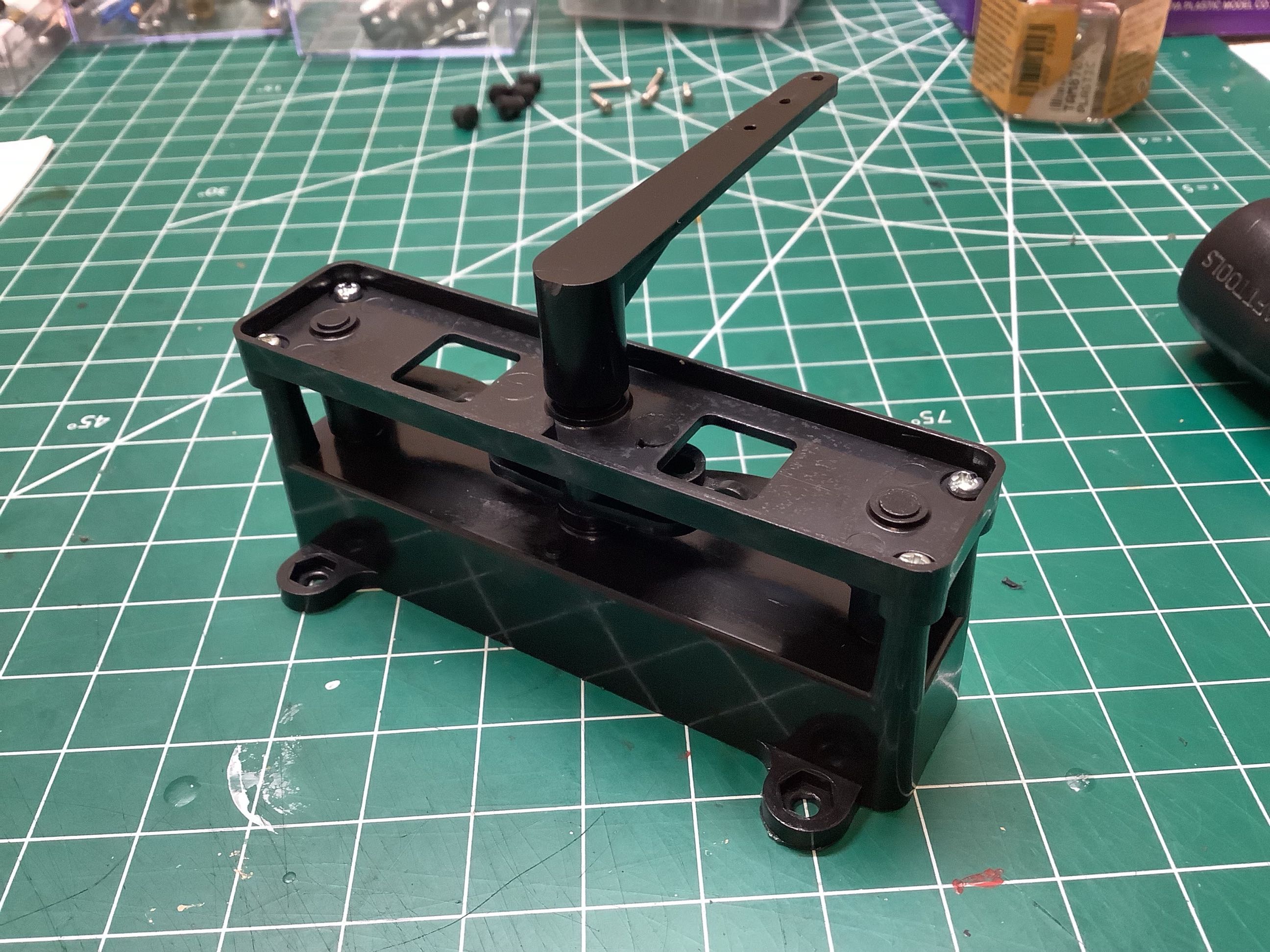
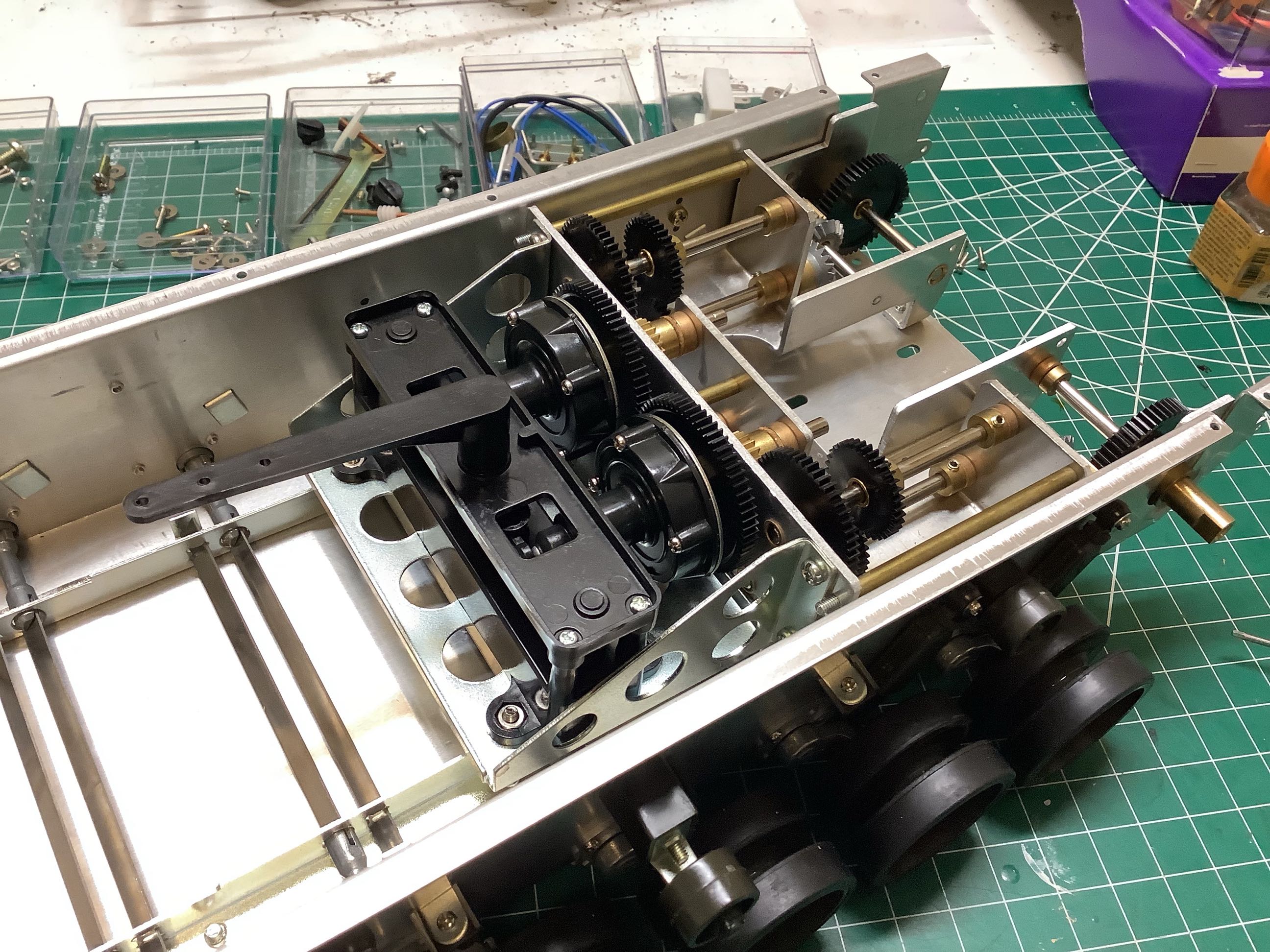
This little mechanism converts servo motion into steering
controls. Those old servos didn't have much torque so it was
important for this mechanism to offer a lot of mechanical
advantage. The very long crank arm shown on the right is driven by
the servo horn. This crank rotates the square drive socket shown
on the left. This socket presses the left or right cam
backward. These cams contact the buttons at the end of the
mechanical clutches, disengaging them.
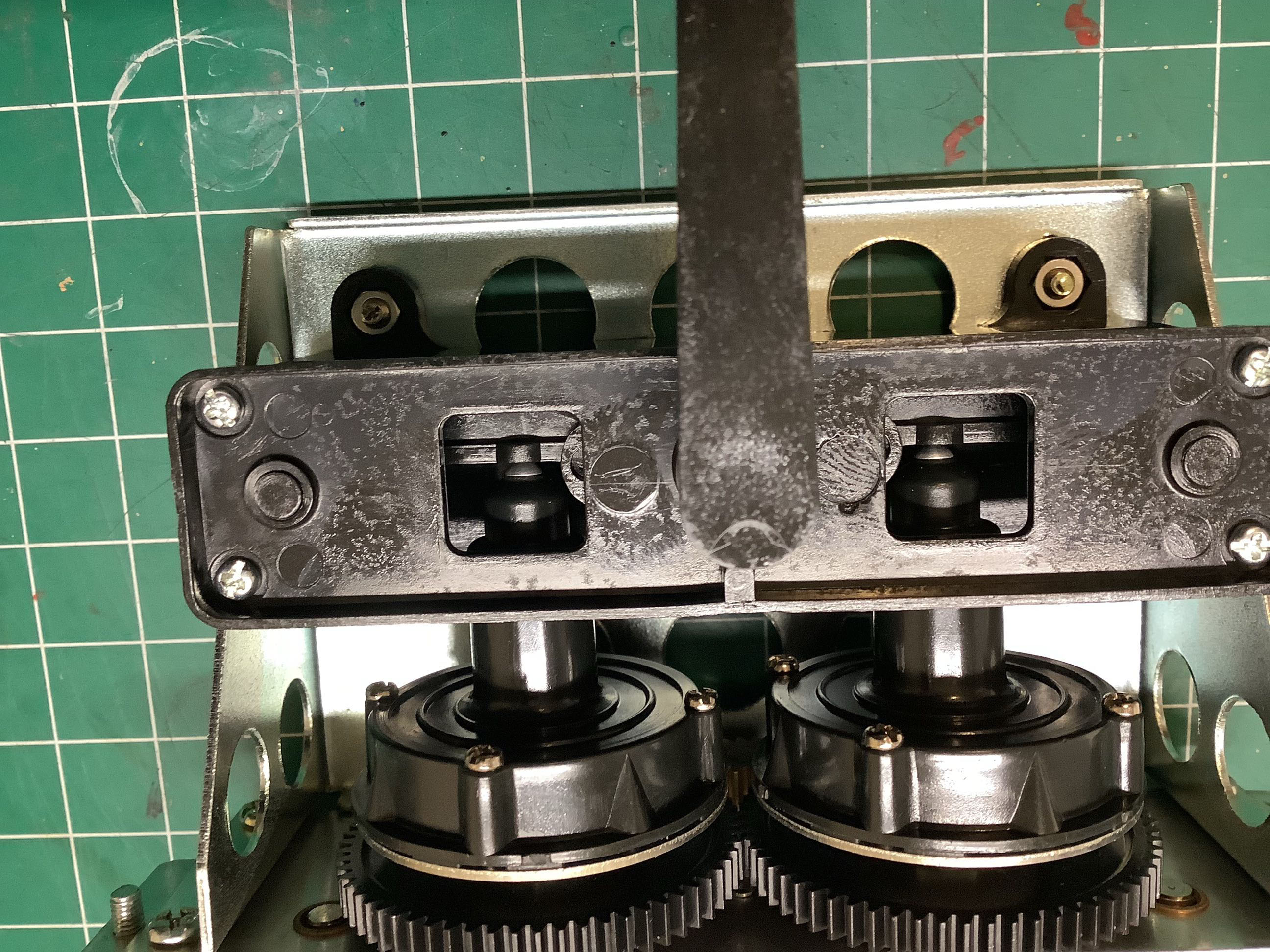
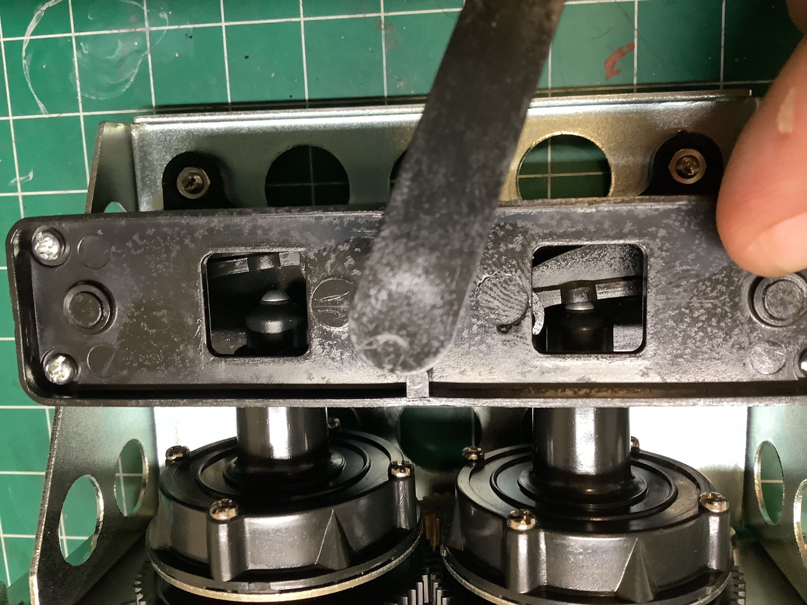
This is a close-up view showing the operation of the steering
system. The picture on the left shows the system at neutral with
both clutches engaged. The gap between the cams and the clutch
buttons can be seen through the square windows and must be calibrated to
be as small as possible. There should be no drag when driving
straight, but very little servo motion should be required to engage the
system. The picture on the right shows a right hand turn.
The square window on the right shows the cam pressing
on the clutch and disengaging it. This is a contact point with
relative motion so it would eventually wear out if driven often.
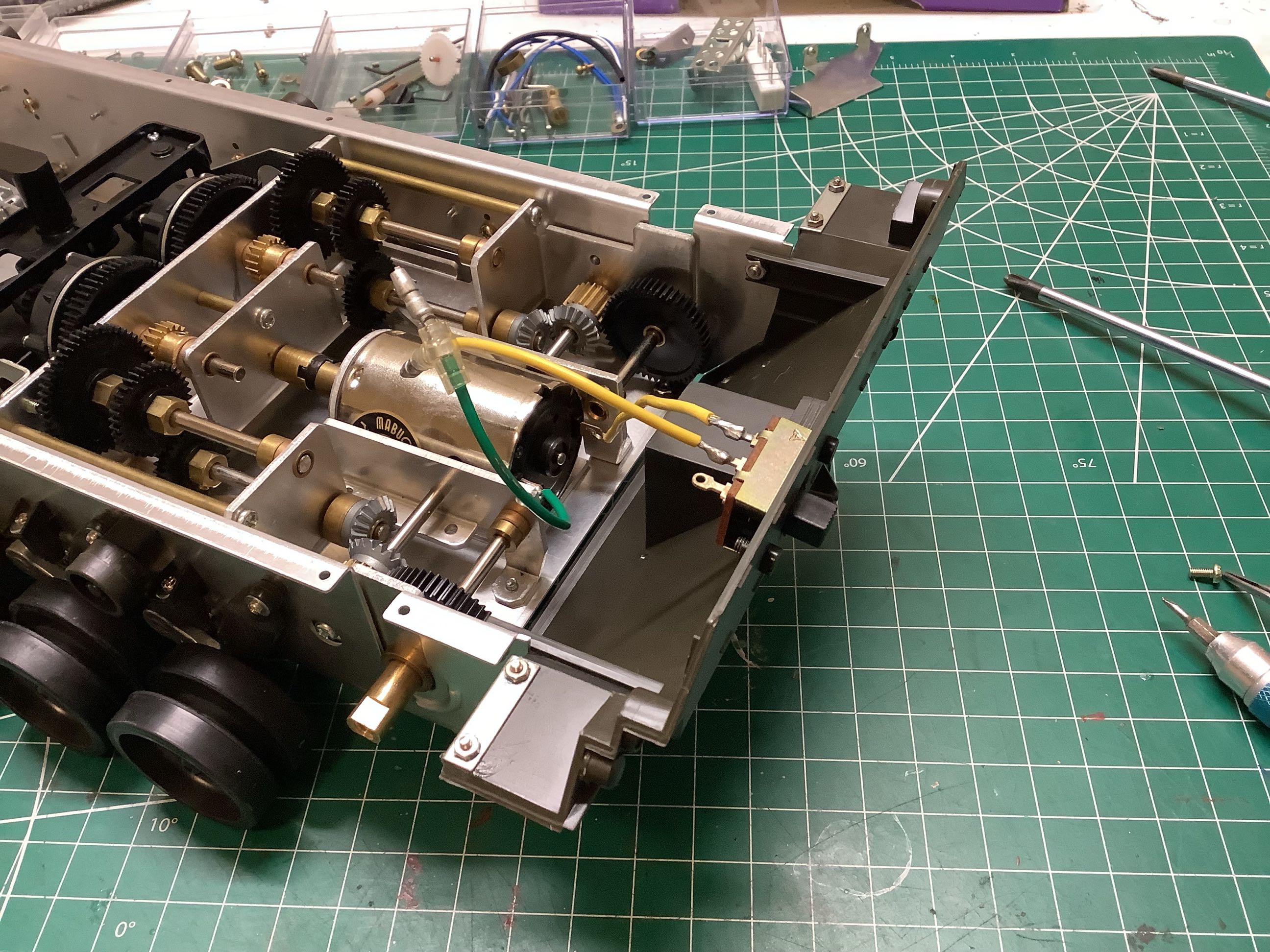
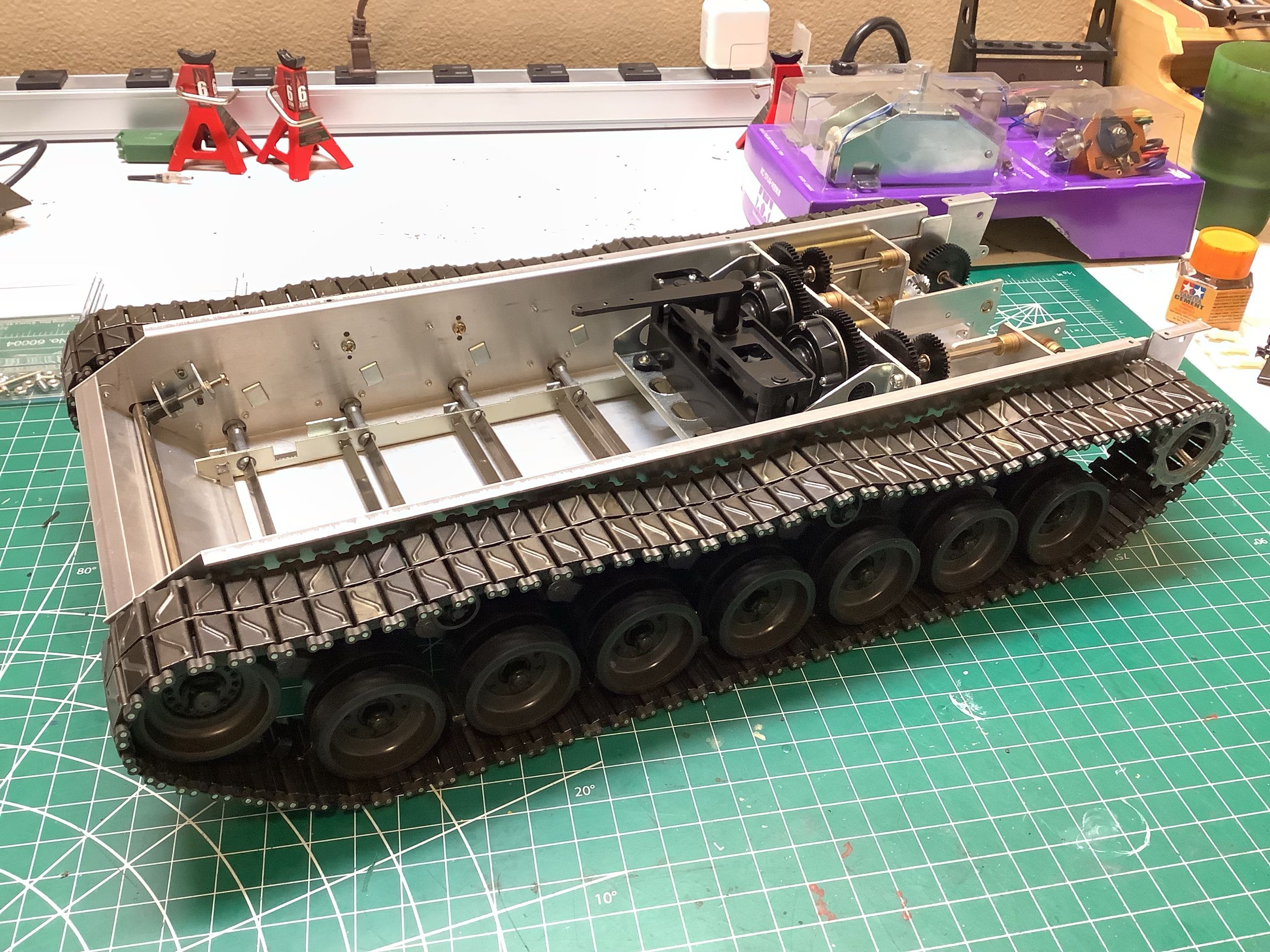
Now the gearbox has been installed into the chassis. The only
protruding areas are the shafts which will connect to the drive
sprockets.
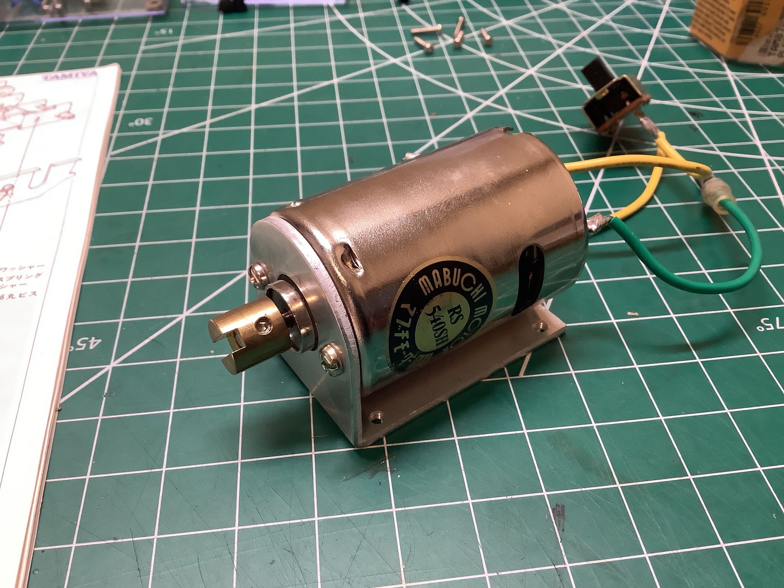
The motor is mated to the gearbox only after the gearbox has been
installed into the chassis. The vintage silver can motor is shown
on the left. The slotted metal collar on the motor drives an
identical collar on the gearbox through a plastic key. The tabs on
the key are rotated 90 degrees on one side compared to the other.
This allows the key to slide on two axes so that the joint can take up
any misalignment between the motor and the gearbox as the motor
spins. The misalignment is visually noticeable and this system
seems to compensate very well. Note that the motor is wired
through a switch on the back panel. This is not really needed for
the RC version, but if you wired it to simply drive straight ahead then
this would be the power switch.
Now the tracks can be fit to the chassis. On
the left you can see how the idler sprocket spins freely on a brass
bushing on the front axle. Again, note that there are no bearings
anywhere on this model. The front axle can be adjusted forward
or back to tension the tracks.
©2021 Eric Albrecht