Tamiya Flakpanzer Gepard Project
Page 3: Building the Suspension
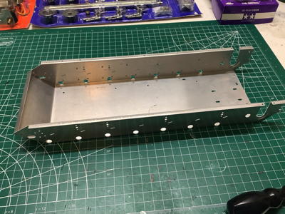
Here is the formed aluminum sheet metal chassis which forms the backbone
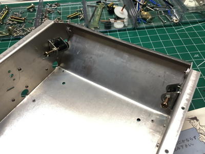
of the tank assembly. The picture on the right shows a pair of
brackets which support adjusting screws. These screws will be used
to push the front axle forward which will serve to tension the tracks
using the front sprockets.
These cast parts are the suspension trailing arms. The slot on the
inner end connects to the rectangular torsion bar (a simple steel
plate) shown which supports the weight of the vehicle and allows
articulation over obstacles and terrain features. The serrations
you see on the spindles are all that holds the road wheels on. A
flexible rubber bushing will be pushed over these serrations and act
both as a wheel bearing and a retainer. The picture on the right
shows the seven arms installed on one side of the chassis. Each
has a bump stop which limits the maximum possible travel.
These pictures show how the torsion bars work. The picture on the
left shows the brackets bolted to the chassis which serve as end locks
for the torsion bars. The torsion bars insert into the X-shaped
recesses. The reason they are X-shaped is so the same part can be
used on both sides. The right hand picture shows all of the
torsion bars installed. Note that the left and right side are
offset slightly in the longitudinal direction.
Here we see the parts that make up the faux shock absorbers. These
are just for show since the piston just slides freely within the
cylinder. On the real tank these would be filled with fluid and
act as dampers. On the right you can see the installed dampers as
well as the 4 return rollers.
Here are the parts to build a road wheel. Each of the seven road
wheels per side is actually made up of dual wheels with a gap between
for the track guide. Each is comprised of two wheels and two
rubber tires as shown. The picture on the right shows the
completed suspension. The chassis can now roll freely.
©2021 Eric Albrecht

