Features
|
|
Pneumatics
This model contains a double acting pneumatic system. The components of
this system are connected with rubber tubing routed through and around
the holes
in the beams.
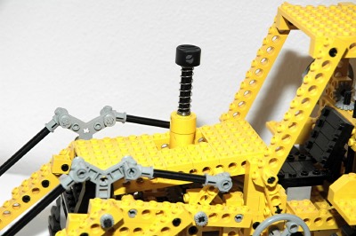
A single pump is integrated into the hook to look like an exhaust
stack. Depression of the piston
produces pressure. The pressure is split and fed to the inlets of
three selector
valves (switches) with two outputs each. Selection of the
switches in
either direction allows pressure to flow to either chamber of the
actuators.
Finally, there are three pneumatic actuators which have ports at the
head and rod ends
to accept input from the switches. Head end pressure extends the
piston, while rod end pressure retracts it. Like a real backhoe,
the
actuators are designed to work in compression during their power
stroke. A real hydraulic actuator has significantly less output
force in tension than in compression due to the fact that the annular
area of the rod end of the cylinder is less than the full bore area of
the head end. |

Click for an animation of the
pneumatic backhoe in action.
|
|
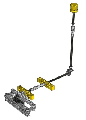
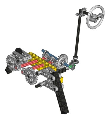
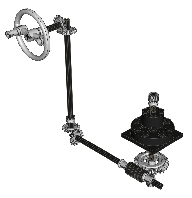
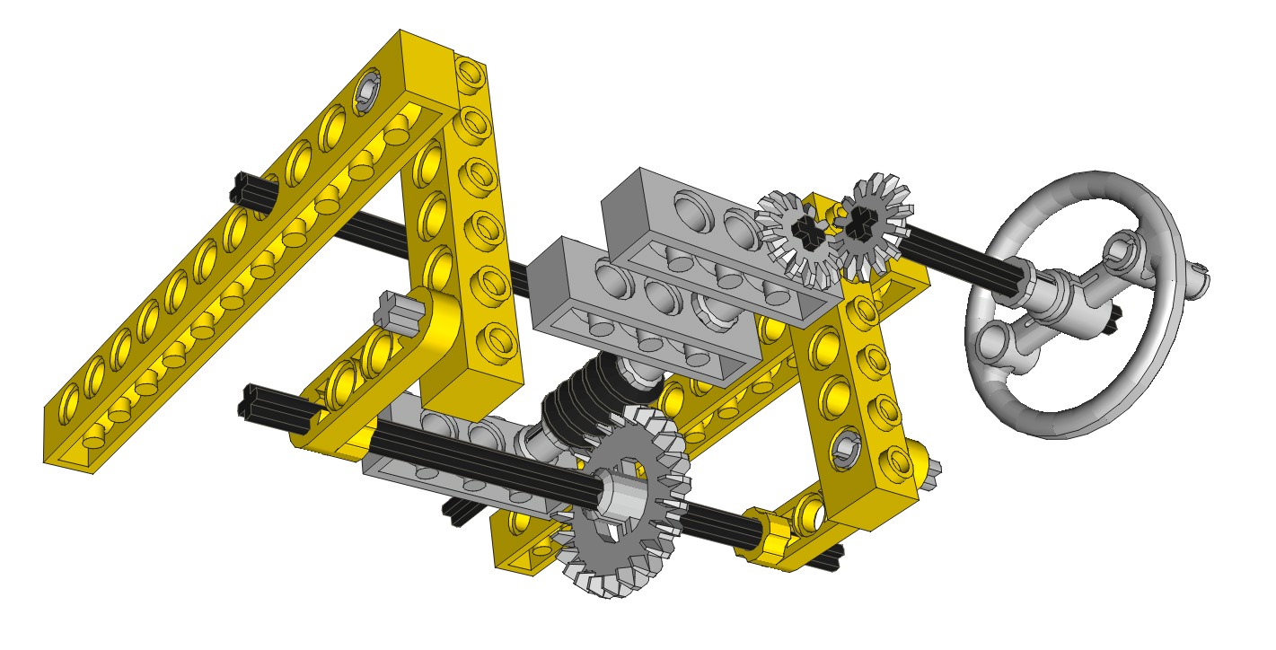
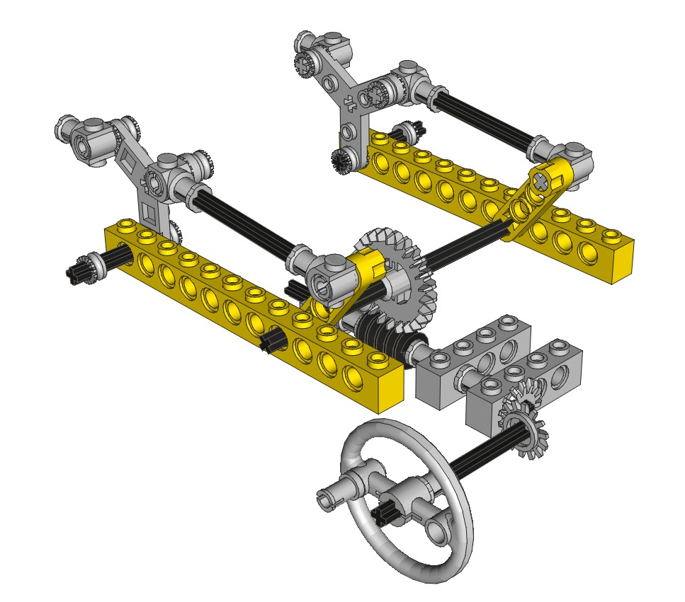
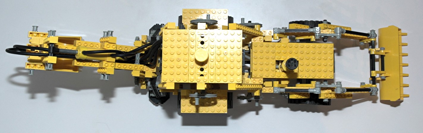
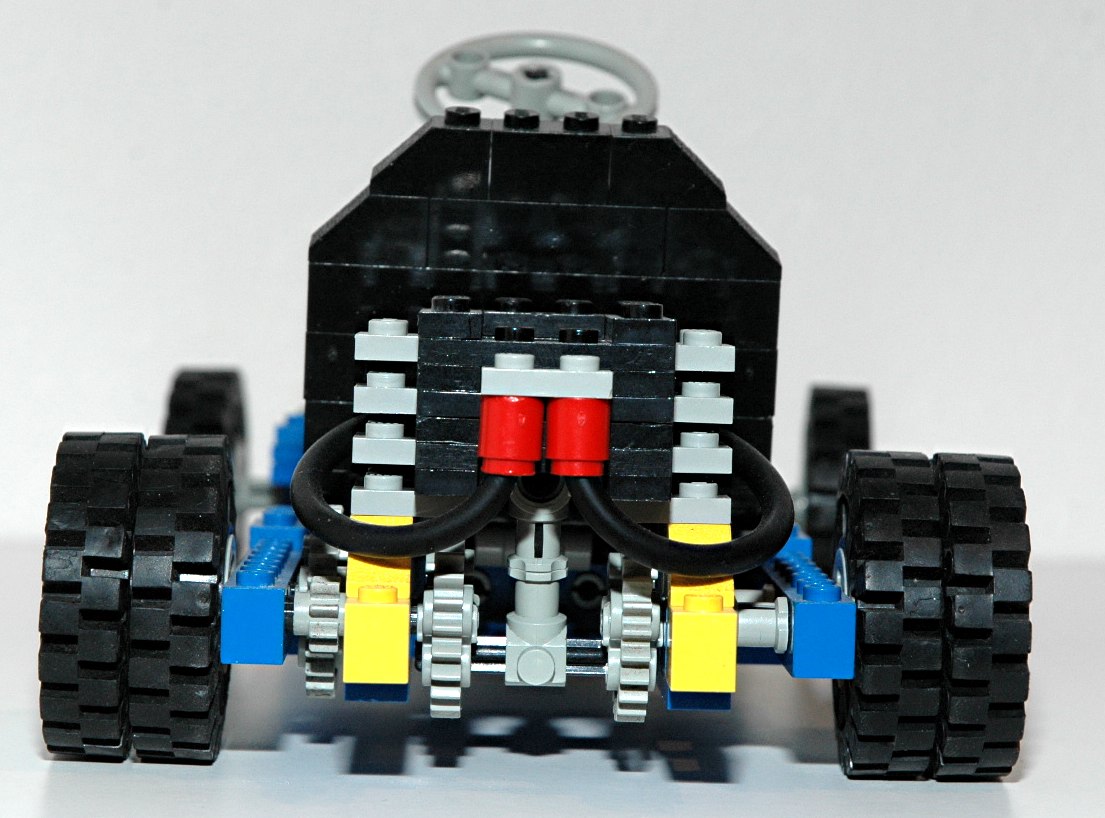
Steering
The front wheels can be steered using an overhead "hand of god" control. The overhead control drives
an axle connected to
a pair of 14 tooth bevel gears through a universal joint.
The second axle drives a rack via an 8
tooth pinion
gear. The steering mechanism itself uses the steering arms
and toothed links as shown in the computer image.
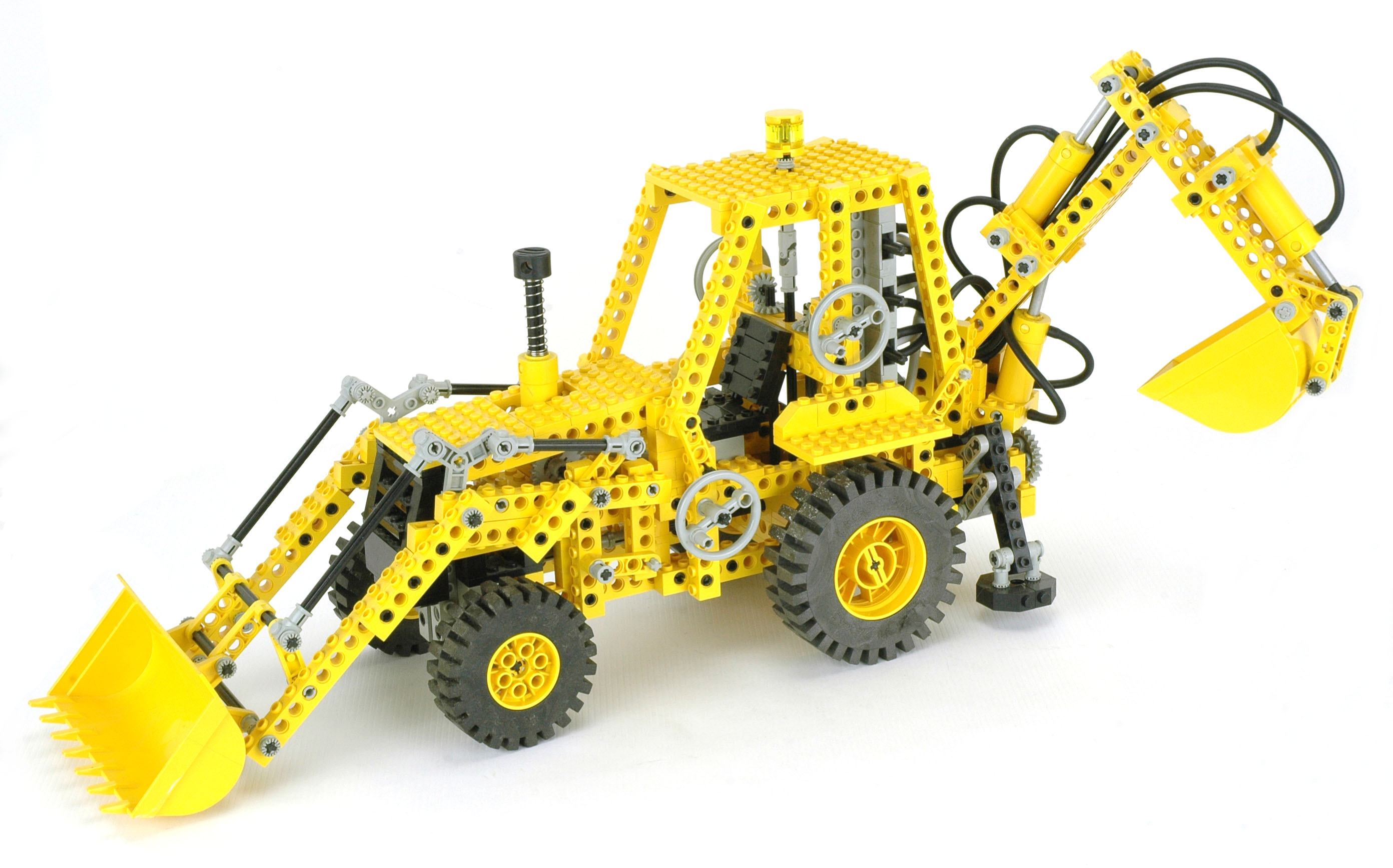
The steering knob is designed to look like a flashing light.
The photo also shows a weighted brick which is used as a counterbalance
to the rear backhoe excavator.
|
Click for an animation of the
steering in motion. |
|
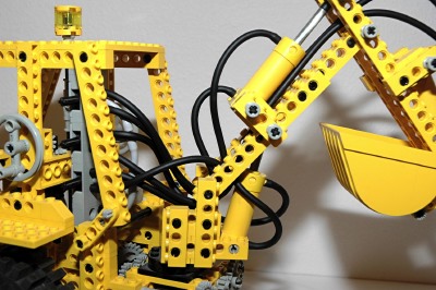
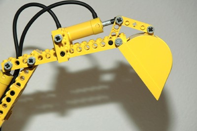
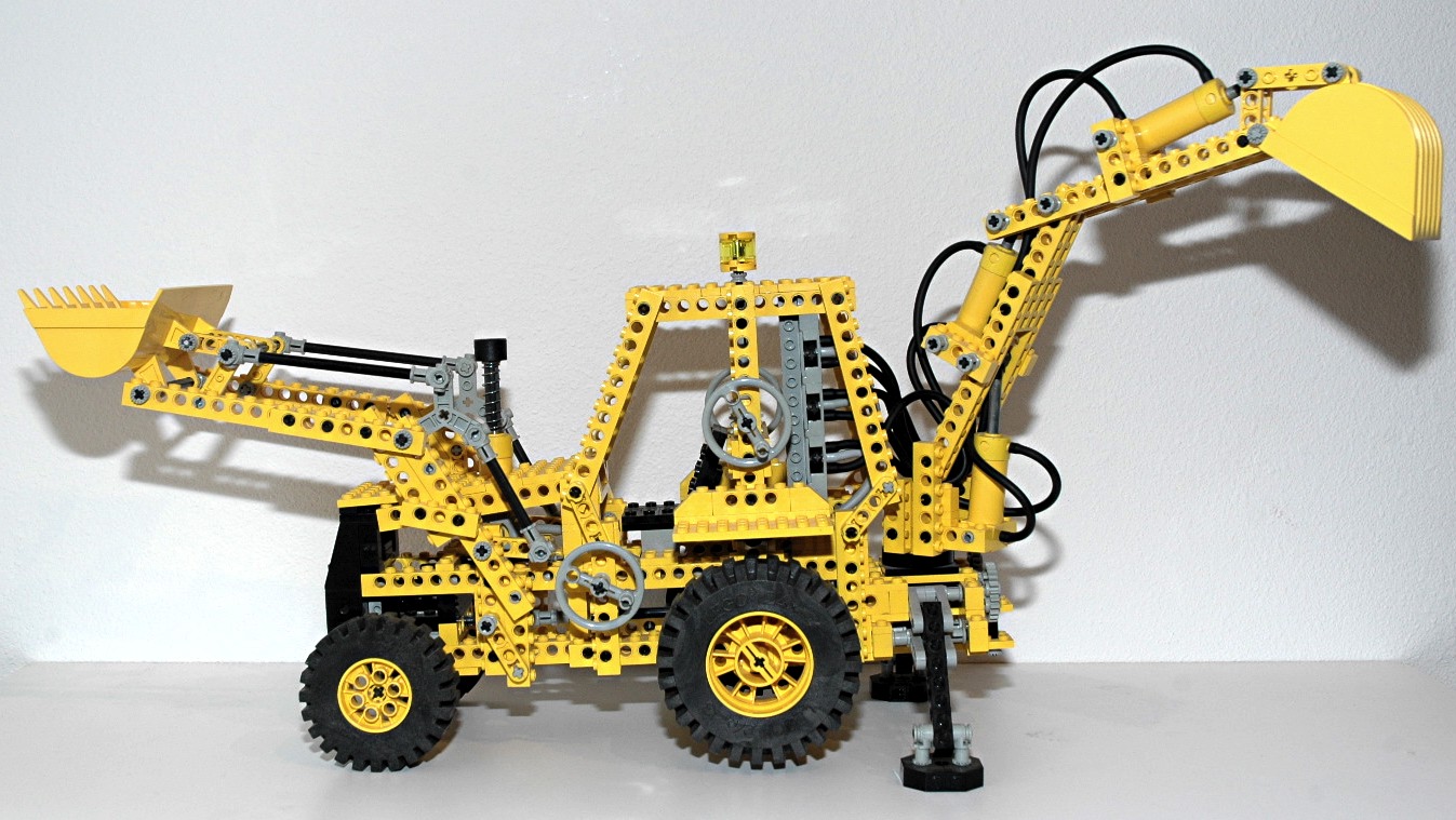
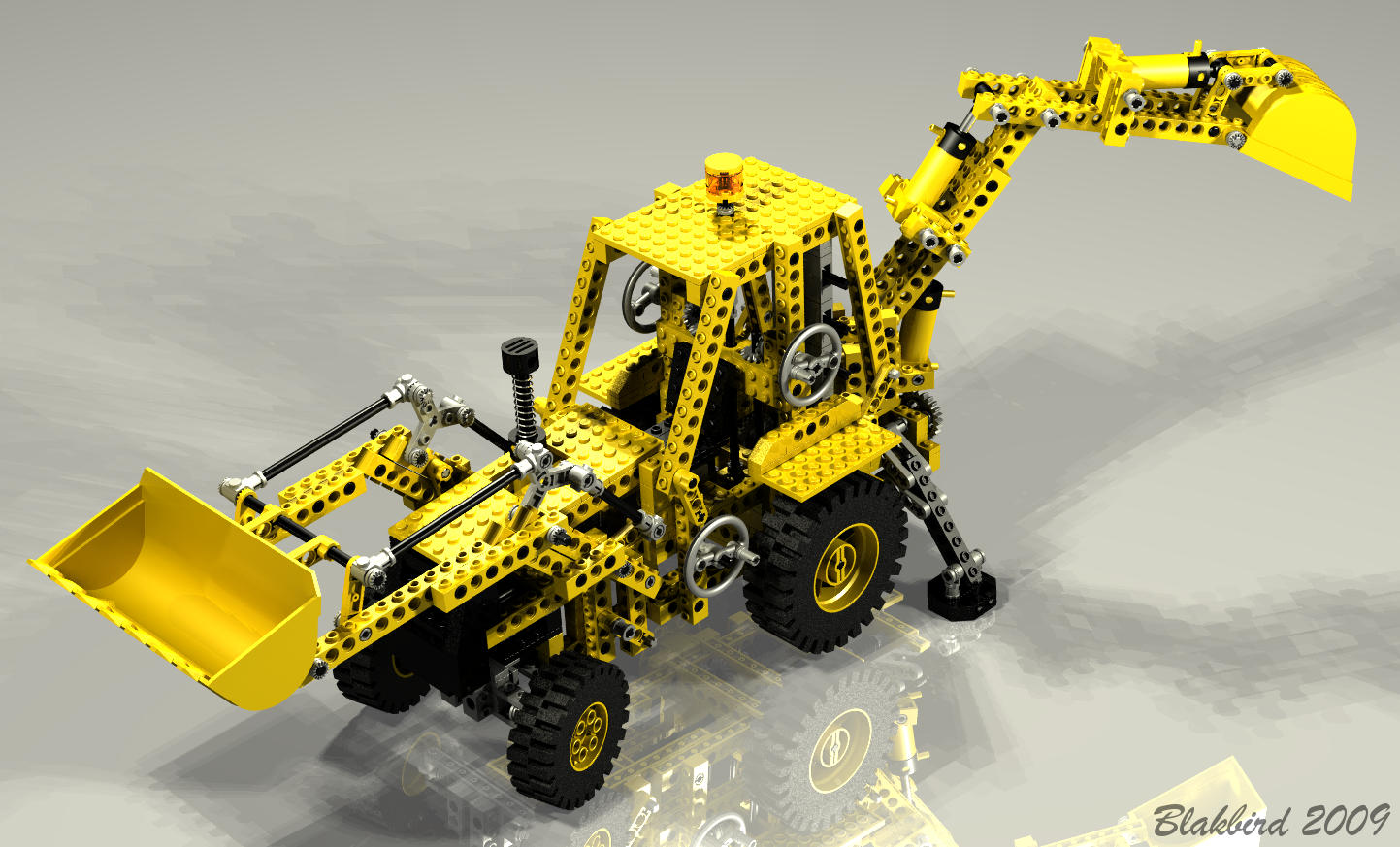
Luffing Backhoe
Boom
The boom can be pivoted from a position almost parallel to the ground
up to an
angle of about 60 degrees. A pneumatic actuator drives
this motion. The actuator has a fairly long moment arm giving it
adequate mechanical advantage. The switch controlling this motion
is on the rear of the cab. |
Click for an animation of the
boom
luffing.
|
|
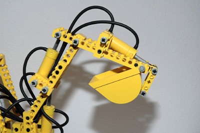
Luffing Backhoe
Jib
The jib can be pivoted around an axis on the end of the boom through an
angle of about 60 degrees. A pneumatic actuator drives
this motion. The switch controlling this motion is on the
rear of the cab. |
Click for an animation of the jib in
motion.
|
|
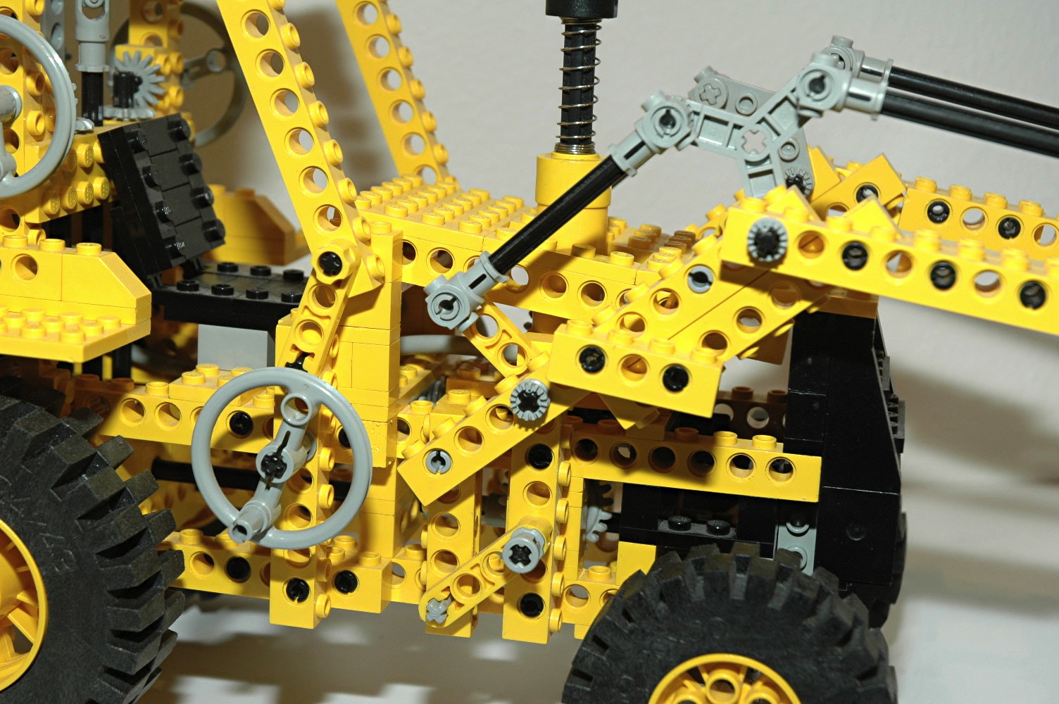
Dumping Backhoe
Scoop
The scoop can be pivoted about an axis on the end of the jib. A
pneumatic actuator drives this motion through a linkage made of
liftarms and rotors. The switch controlling this motion is on the
rear of the cab. |
Click for an animation of the scoop
in motion. |
|
Slewing
The rotation of the boom is accomplished via a crank on the left
side. This crank passes torque through two sets of 14 tooth bevel
gears and then into a worm gear. The worm gear drives a 24 tooth
crown resulting in a reduction of 24:1. The final gear
turns a threaded axle which passes through an old 4x4 turntable.
Axle nuts on the top and bottom of the threaded axle provide clamping
force which keeps the moment of the boom from tipping itself free of
the turntable.
Because the pneumatic hoses pass between the cabin and the boom, the
boom can only slew about 180 degrees before the hoses become
twisted. The boom can only be pivoted when the outriggers are
deployed or they block its motion and lock it in the centered position.
|
|
|
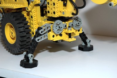
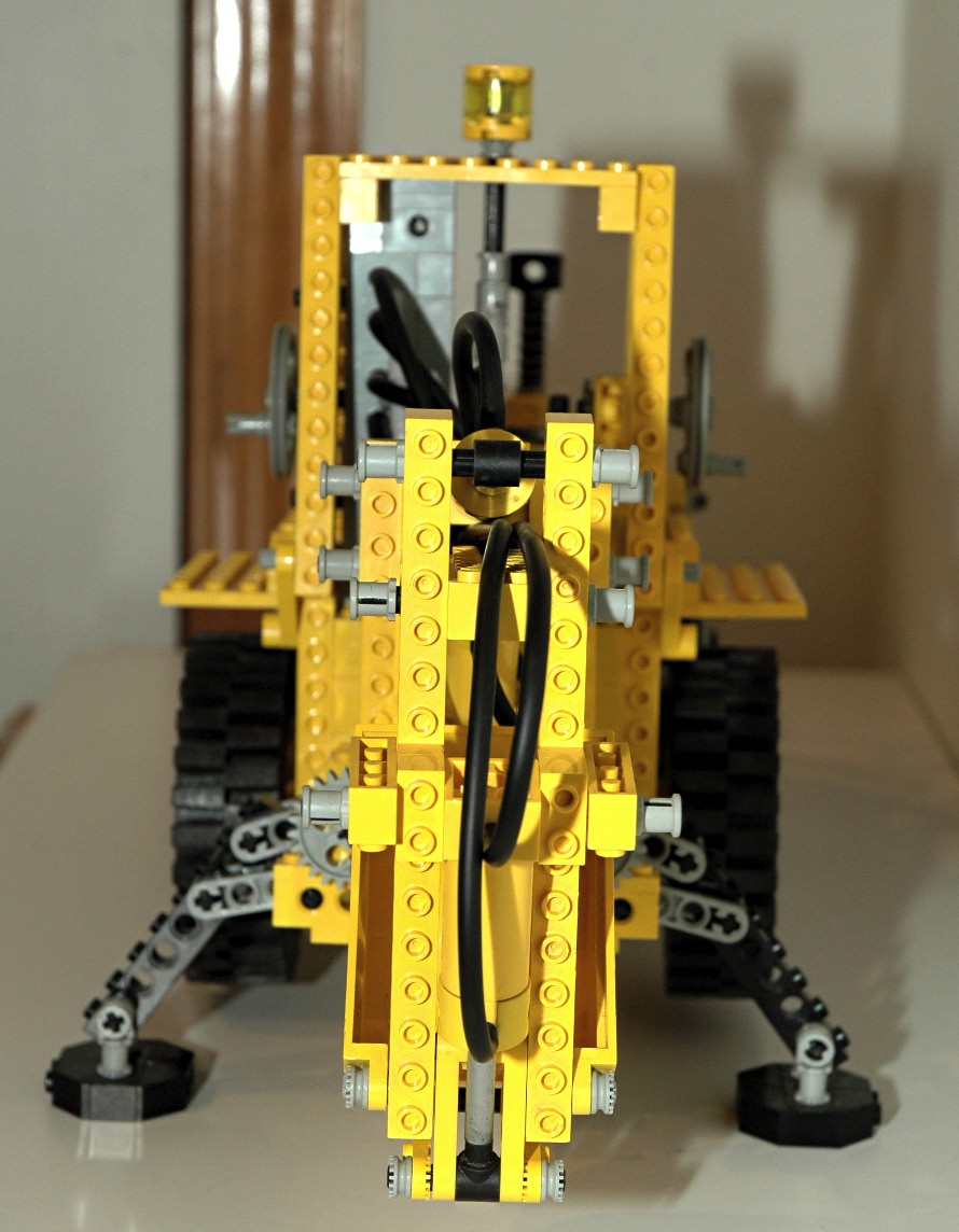
Outriggers
There are a pair of outriggers behind the rear wheels which are
constructed using the new 1x4 liftarms and standard beams. The
feet are made from beams and sloped bricks.
The color coded computer image shows the mechanism. A crank on
the right side drives two sets of 14 tooth bevel gears (black and green
axles). Next a worm gear (green axle) drives a 24
tooth crown gear (blue axle) resulting in 24:1 reduction. The
crown gear on the blue axle
drives a pair of 16 tooth spur gears (red axles) in opposite
directions (16:24). Each red axle drives an outrigger after
passing
through a set of 24 and 8 tooth gears (24:8), resulting in a final gear
reduction of 48:1. When constructing the
outriggers, care must be taken to keep these two gears in phase so the
outriggers will be even.
Due to a careful selection of geometry, the outriggers are
self-locking. When fully deployed, weight on the foot tends to
rotate the two sets of liftarms together, locking the assembly, rather
than trying to backdrive them. It is this geometry, rather than
the worm gear, that prevents the outriggers from collapsing under
weight.
The outriggers provide a wide base for stability and are significantly
taller than the rear tires so that the tires are lifted off of
the
ground. |
Click for an animation of the
outrigger
in motion.
|
|
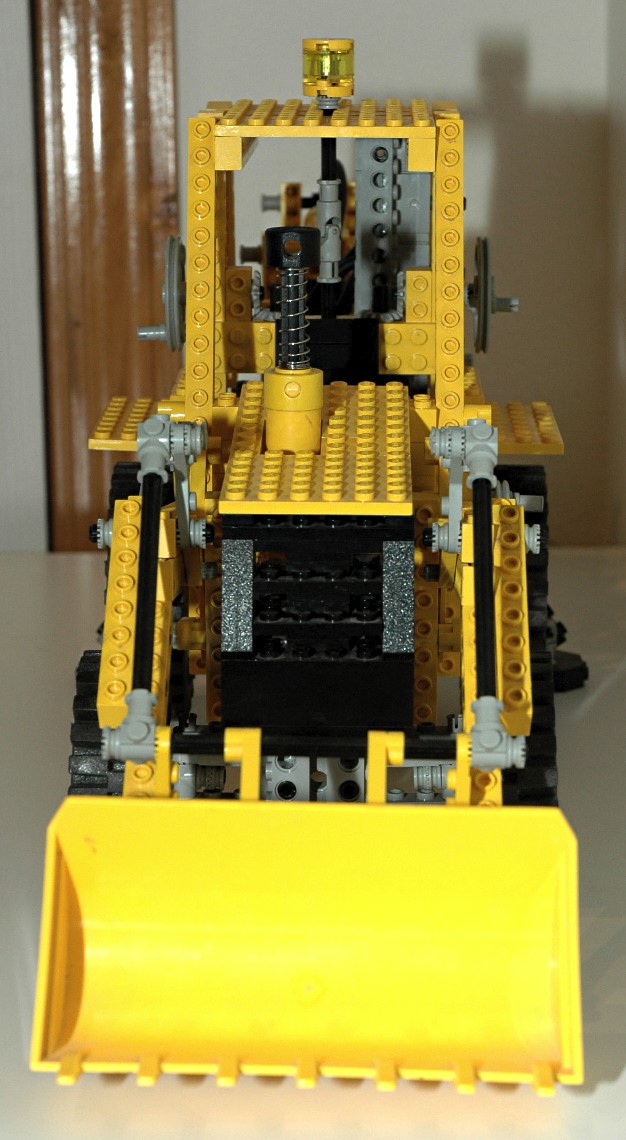
Lifting Loader
Bucket
The front bucket can be lifted and dumped in a manner almost identical
to that used on the 8853 loader. Input
is via a crank on the right of the
vehicle. The crank drives a pair of 14 tooth bevel gears.
The torque then turns a worm gear. The worm gear mates with a 24 tooth
crown gear,
resulting in 24:1 gear reduction. The crown gear axle attaches to
liftarms which act as cranks. The crank
arms
push and pull 6L beams used as links which drive the bucket boom up and
down.
The use of a worm gear results in a system which cannot be backdriven
(because the axial friction is higher than the
backdriving torque due to the screw pitch angle) which allows the
bucket to be supported so that it does not fall under its own weight.
Because the boom pivot and the dumping mechanism share an axle, their
movement is dependent. As you can see in the animation, even
though the dumping mechanism link remains fixed in space, it rotates
with respect to the boom as the boom lifts resulting in the bucket
dumping slightly. |


Click for an animation of the loader
lifting. |
|
Dumping Loader
Bucket
The front bucket can be dumped via a crank on the left of the
vehicle. The crank drives a pair of 14 tooth bevel gears and then
a worm
gear. The worm gear mates with a 24 tooth crown gear,
resulting in 24:1 gear reduction. The crown gear axle attaches to
liftarms used as cranks. The crank arms drive a set of push/pull
rods which control
rotation of the bucket. The motion is transferred past an
angle change in the boom using a pair of 3 blade rotors.
The use of a worm gear results in a system which cannot be backdriven
(because the axial friction is higher than the
backdriving torque due to the screw pitch angle) which allows the
bucket to be supported so that it does not fall under its own weight.
|
|
|
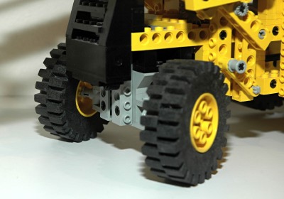
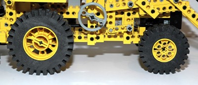
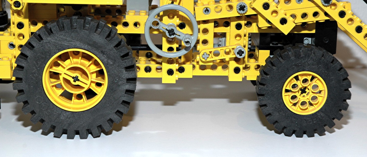
Wheels and Tires
This set uses two of the smaller size foam 20x30 tires and wheels in
the front, and two foam 24x43 tires and wheels in the back. This
is the only set to
ever have these large wheels in yellow. |
|


