Features
|
|
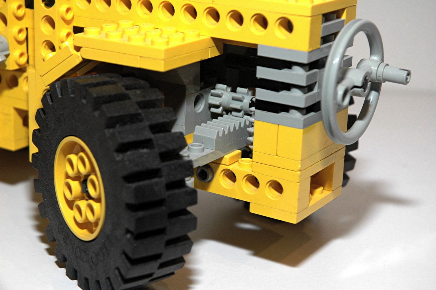
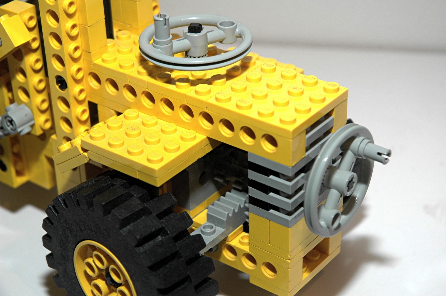
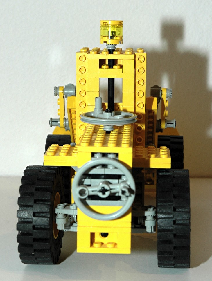
Steering
The rear wheels can be steered using an overhead "Hand of God" control.
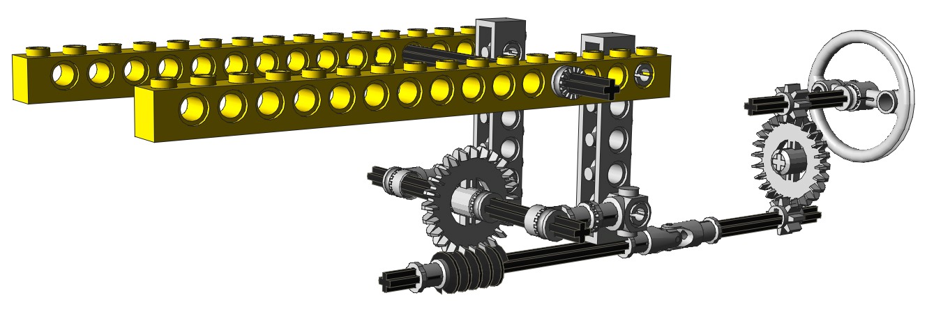
The overhead control drives an axle connected to a pair of 14 tooth
bevel gears. The second axle drives a rack via a pair of 8 tooth
pinion
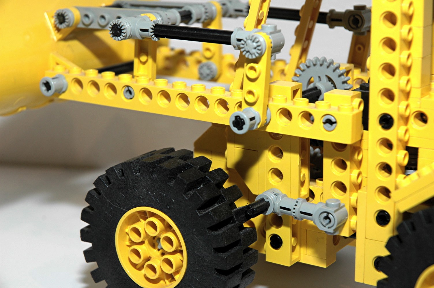
gears. The steering mechanism itself uses steering arms and
toothed links as shown in the computer image.
|
Ldraw file courtesy of Benjamin Wendl.
Click for an animation of
the
steering in motion
|
|
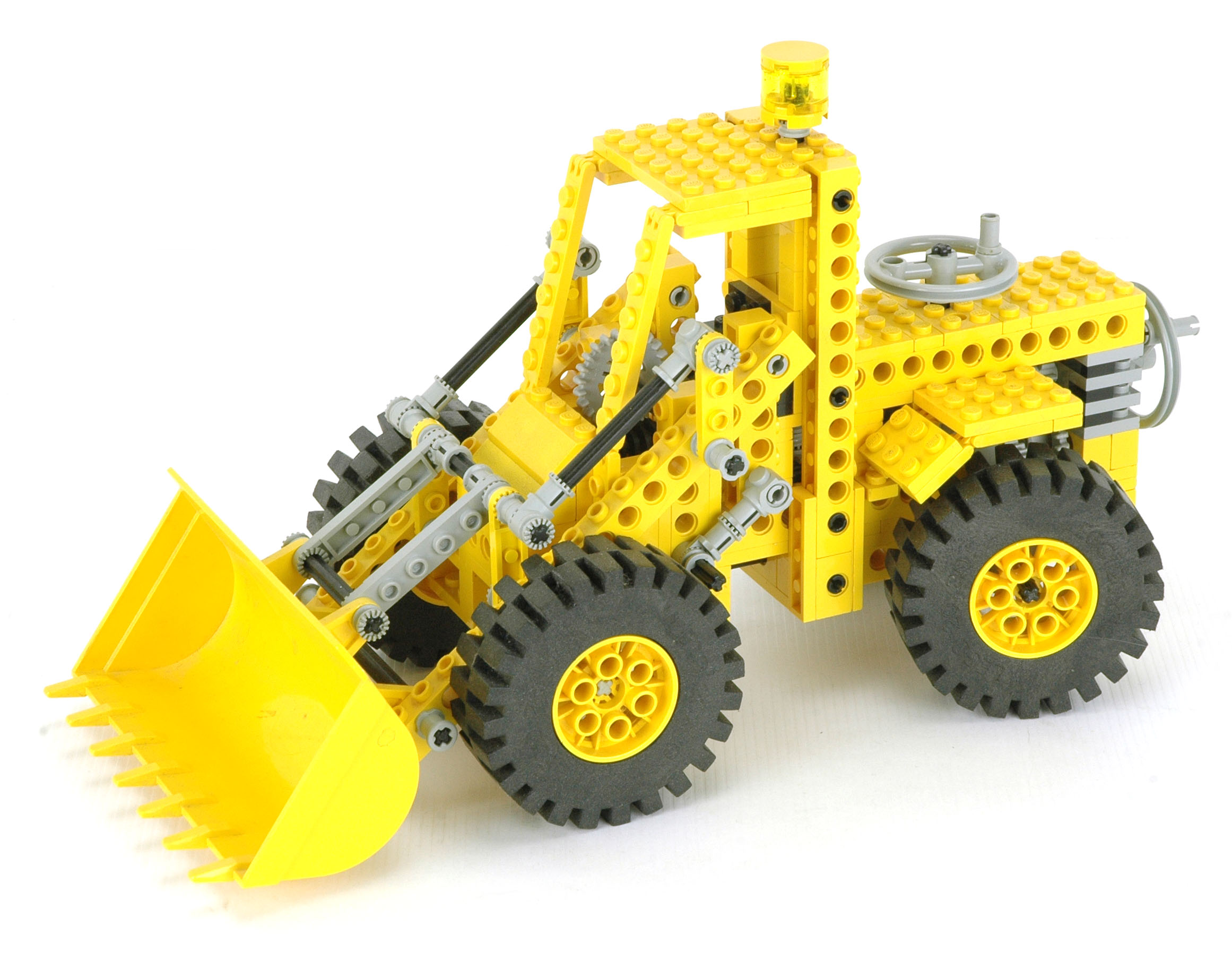
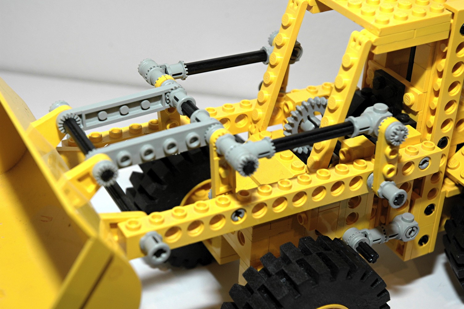
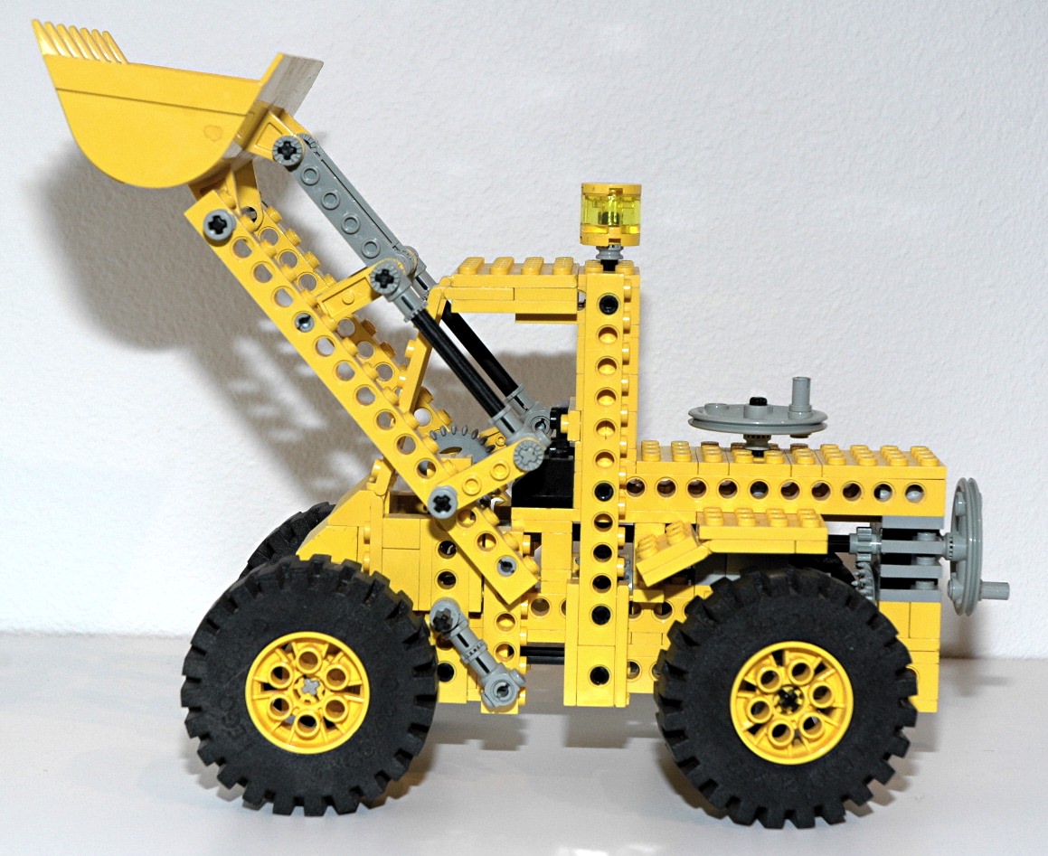
Bucket Lift
The front bucket can be lifted via a crank in the rear of the
vehicle. The crank drives an 8 tooth pinion which passes through
a 24 tooth crown gear and then another 8 tooth pinion, cancelling out
the gear ratio change. The torque the passes through a U-joint
and turns a worm gear. The worm gear mates with a 24 tooth crown gear,
resulting in 24:1 gear reduction. The crown gear axle attaches to
toothed connectors which rotate a pair of crank arms. The crank
arms
push and pull 6L beams used as links which drive the bucket boom up and
down.
The use of a worm gear results in a system which cannot be backdriven
(because the axial friction is higher than the
backdriving torque due to the screw pitch angle) which allows the
bucket to be supported so that it does not fall under its own weight.
Because the boom pivot and the dumping mechanism share an axle, their
movement is dependent. As you can see in the animation, even
though the dumping mechanism link remains fixed in space, it rotates
with respect to the boom as the boom lifts resulting in the bucket
dumping.
|


Ldraw file courtesy of
Benjamin Wendl.
Click for an animation of the
bucket
lifting.
|
|
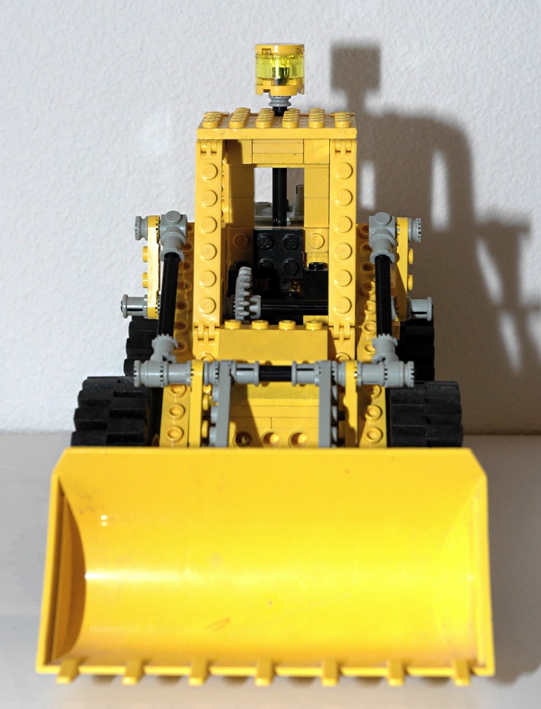
Dump
The front bucket can be dumped via a crank on the top rear of the
vehicle. The crank drives a pair of 14 tooth bevel gears and then
a pair of 8 tooth spur gears, one of which is connected to a worm
gear. The worm gear mates with a 24 tooth crown gear,
resulting in 24:1 gear reduction. The crown gear axle attaches to
toothed bushings which rotate a pair toothed links used as crank
arms. The crank arms drive a set of push/pull rods which control
rotation of the bucket.
The use of a worm gear results in a system which cannot be backdriven
(because the axial friction is higher than the
backdriving torque due to the screw pitch angle) which allows the
bucket to be supported so that it does not fall under its own weight.
The orientation of the toothed bushings and connectors in this system
is very important. If the bushing faces a link, they lock together
and move with the axle. If the bushing faces away from the link,
the link can rotate freely on the axle. The top
view shows this clearly.
|
|
|
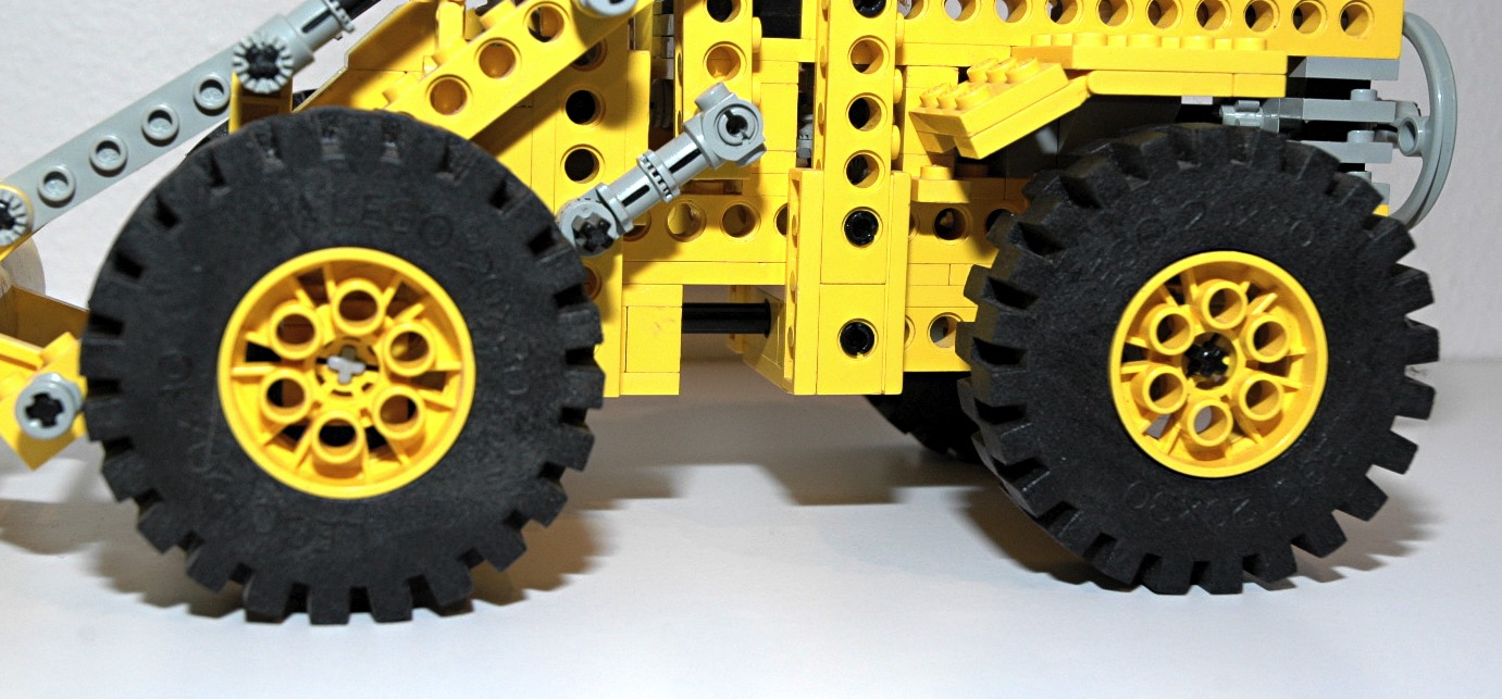
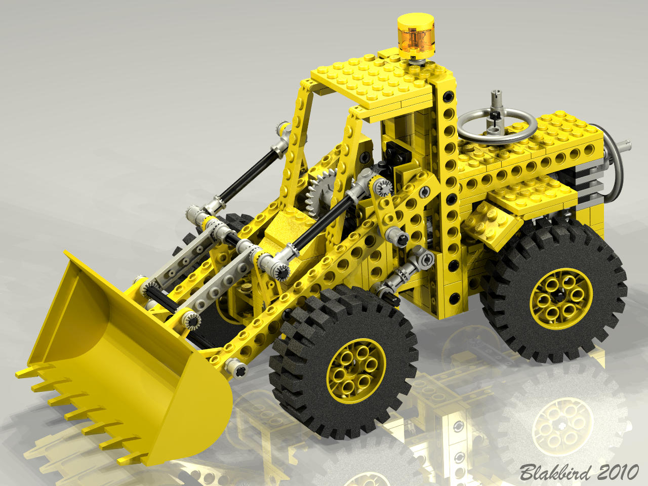
Wheels and Tires
This set uses four of the smaller size foam 20x30 tires and wheels.
|

|


