Double Acting
Pneumatics
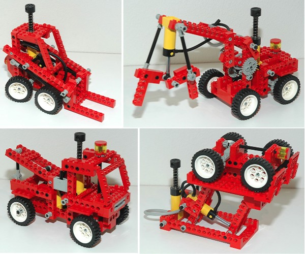
This second generation pneumatics, released this year,
fixed all the problems of the previous system. The double acting
cylinders could be pressurized on either side, allowing significant
force to be generated in either tension or compression.
- Actuator: There are two pressure ports, one at the
head end for extension and one at the rod end for retraction. The
limitation on the force is that the piston head internal to the
actuator (or pump) will begin to
leak after a certain pressure, acting as a pressure relief valve.
Since the annular area of the rod end chamber is smaller than the area
of the head end chamber, the maximum tension force of the actuator is
smaller than the maximum compression force. This is why most real
hydraulic construction equipment orients the actuators so that the
power stroke is during actuator extension.
- Pump: The pump has the same lower housing as the
actuator. The upper end is a large piston with a compression
spring return.
- Switch: The switch is the same as under the old
pneumatic system. The switch is really a pneumatic selector
valve and is the size of two 1x2 bricks. The outer ports are
connected to the two ports of the actuator. The center
port runs to the pump. When the switch is at the
center position, all ports are blocked. When the switch is moved
to one position or the other, one of the outer ports and the center
port are connected to the distribution block and the other is vented to
atmosphere.
Compression Summary: Depression of the pump produces
pressure. Pressure flows to center port of switch. Pressure
flows out enabled port to actuator head end, extending it. Return
pressure from the rod end vents through the other port of the
switch. Return of the pump draws
in air through the switch.
Tension Summary: Depression of the pump produces
pressure. Pressure flows to center port of switch. Pressure
flows out
enabled port to actuator rod end, retracting it. Return pressure
from
the head end vents through the other port of the switch. Return
of the
pump draws
in air through the switch.
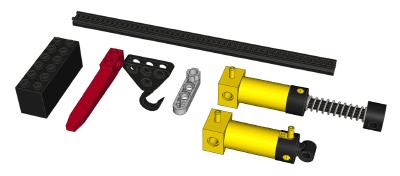
Liftarm
The new liftarm part is 1x4 with an axle slot at each end. 3/4 of
the part is 1/2 stud thick, with the far end a full stud thick and
notched to fit between 4 studs on a plate or brick. This part
could be used as a crank and served as the prototype for many other
sizes and shapes of liftarms to come which would be used prolifically
for decades.
Rack
Gear
A new rack gear was introduced which is much longer (1x20) than the old
1x4.
The gear teeth are recessed rather than standing proud of the
base plate like the old rack. This rack is used principally to
telescope long structures such as the boom of a crane. It's uses
are not limited to Technic and, in fact, it was only ever used in one
Technic model.
Fork
A special part was introduced to act as a fork for forklifts. It
was only ever used for this purpose in Technic (on 4 different fork
lifts). It is quite rigid
and can support considerable weight.
Hook
A new hook part was the first all metal part in Technic. The
significant weight of this part helped to keep the cables attached to
it pulled taut.
Weight
A special brick appeared (new to Technic) which was 2x6x2 and filled
with ballast. It was only ever used in three Technic sets to
counterbalance heavy structures which could otherwise tip.
|
|


