Features
|
|
Mechanical Functions
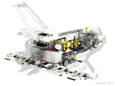
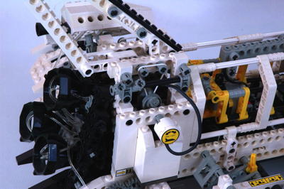
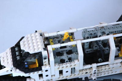
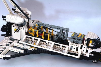
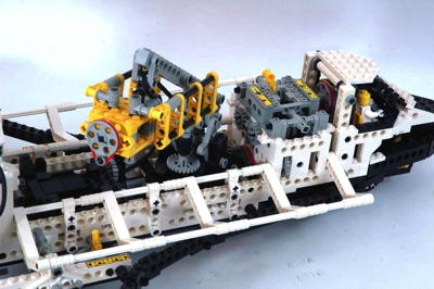
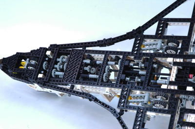
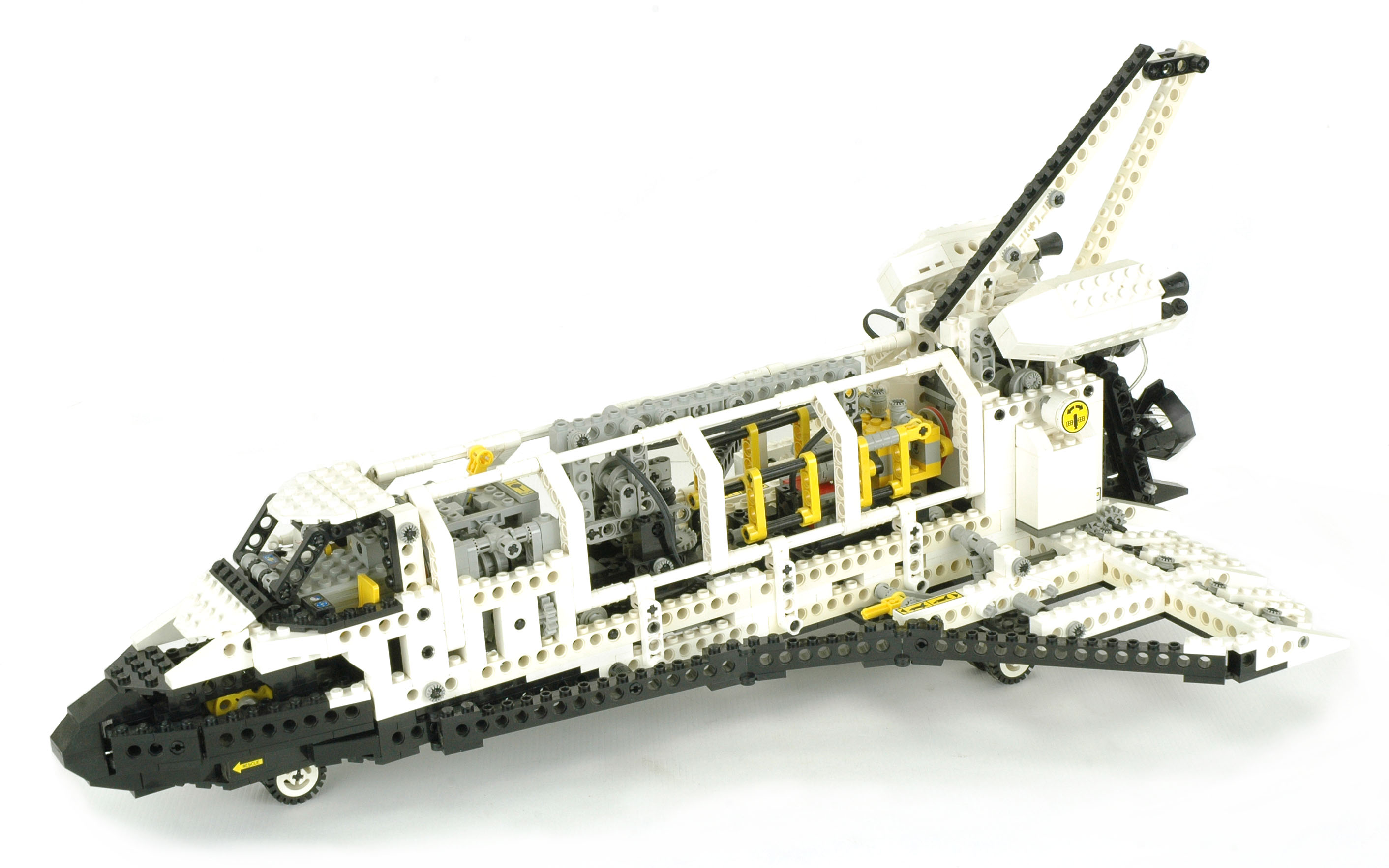
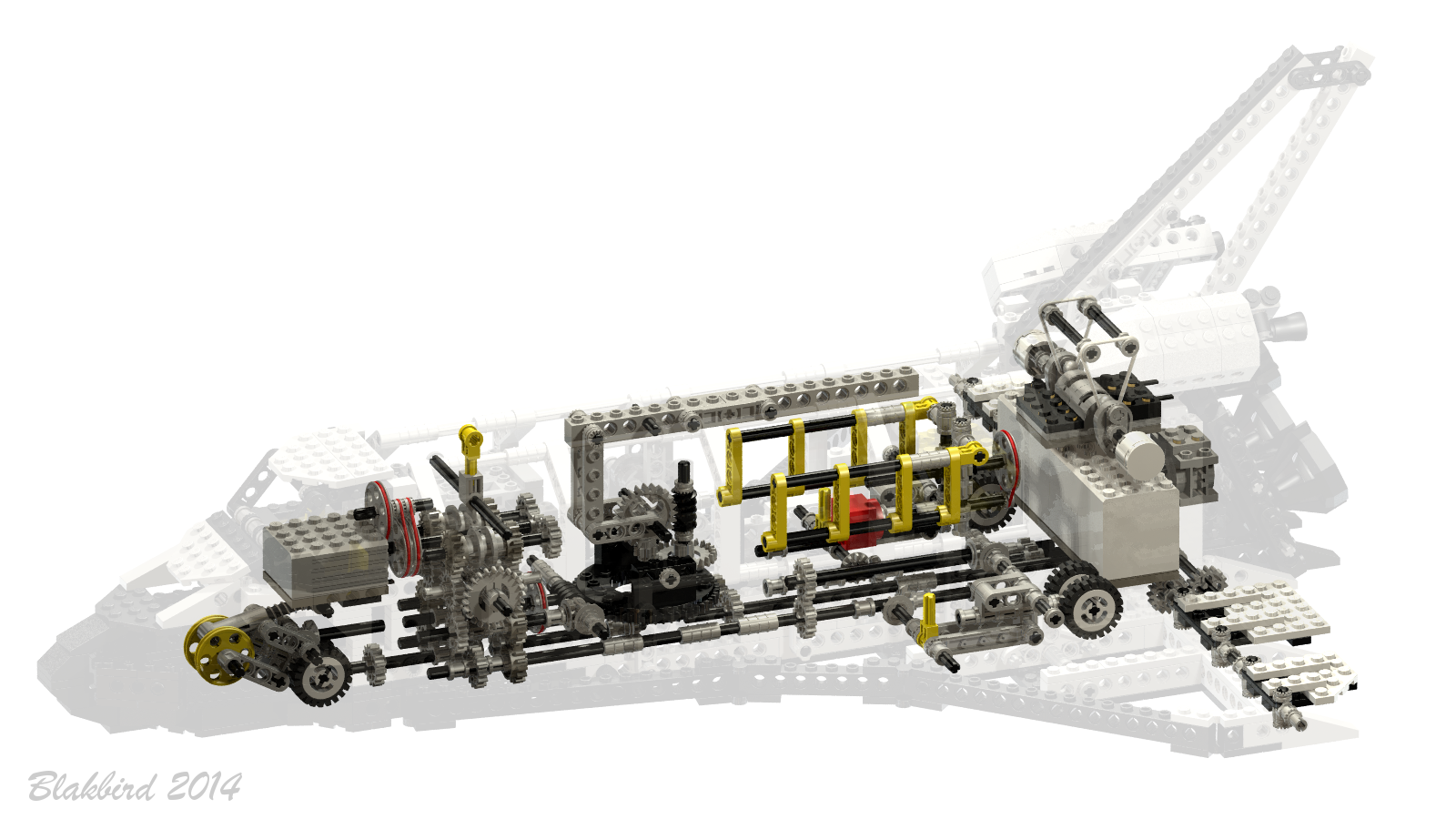
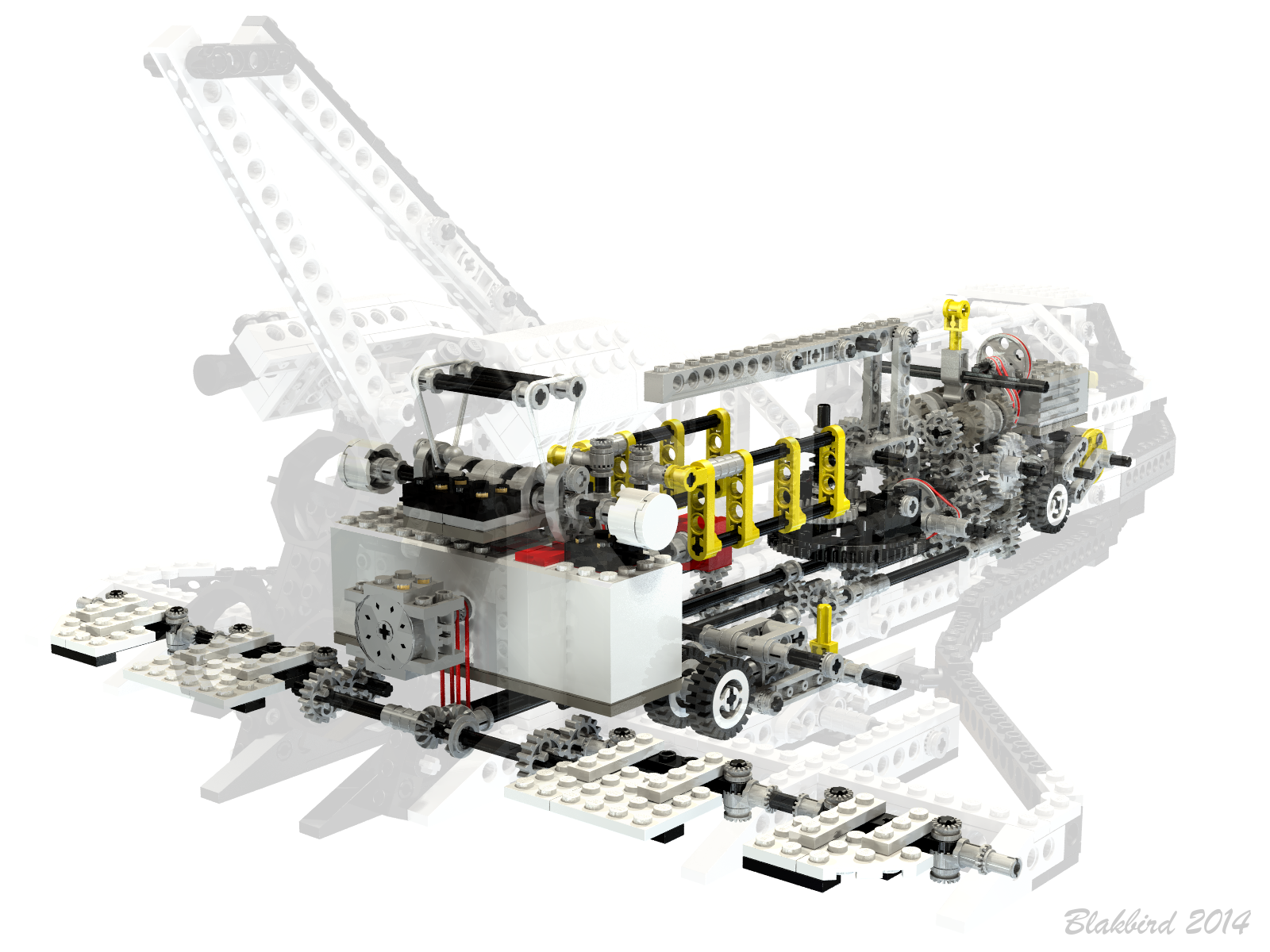
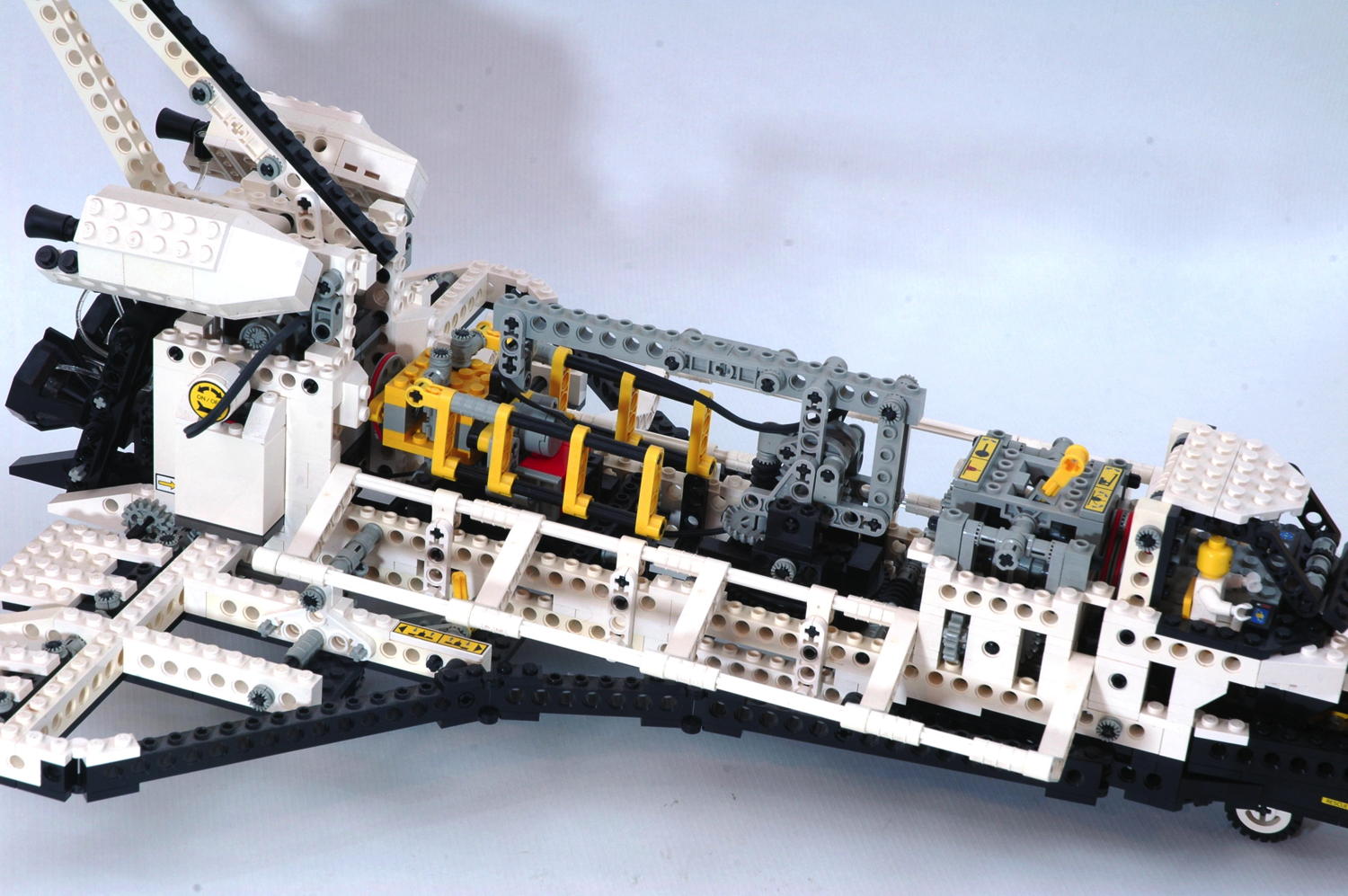
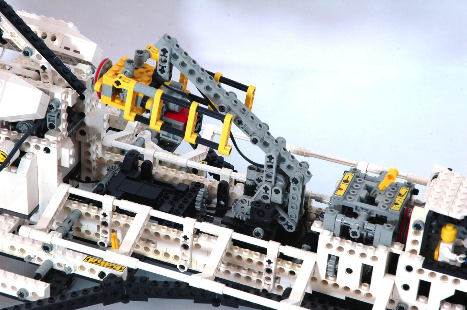
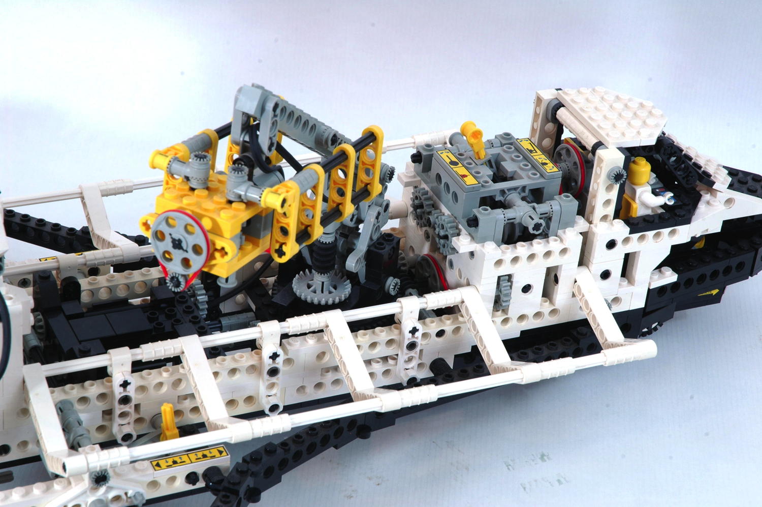
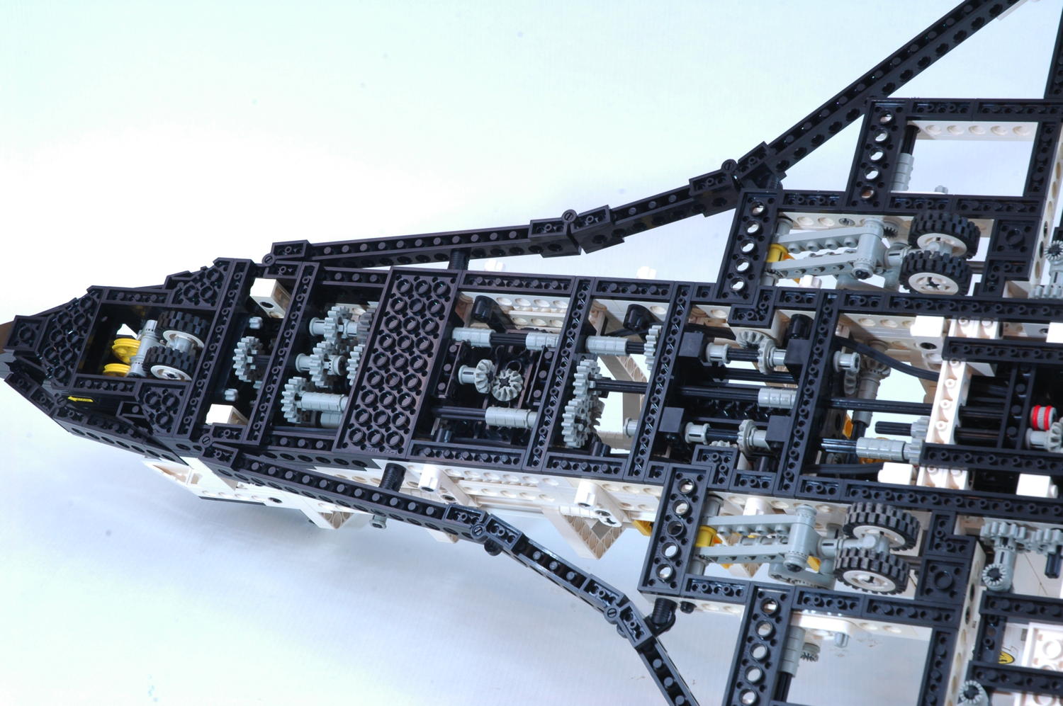
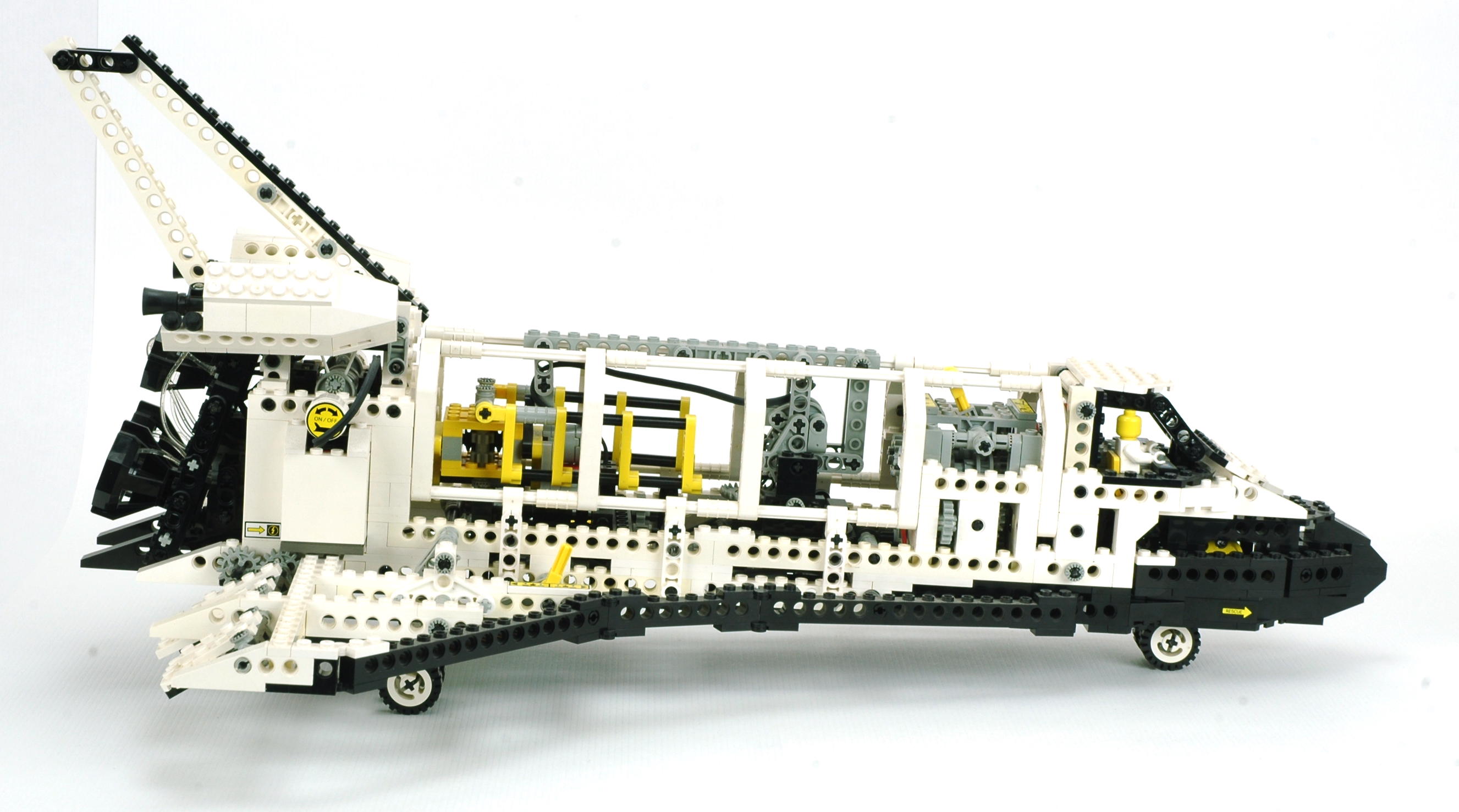
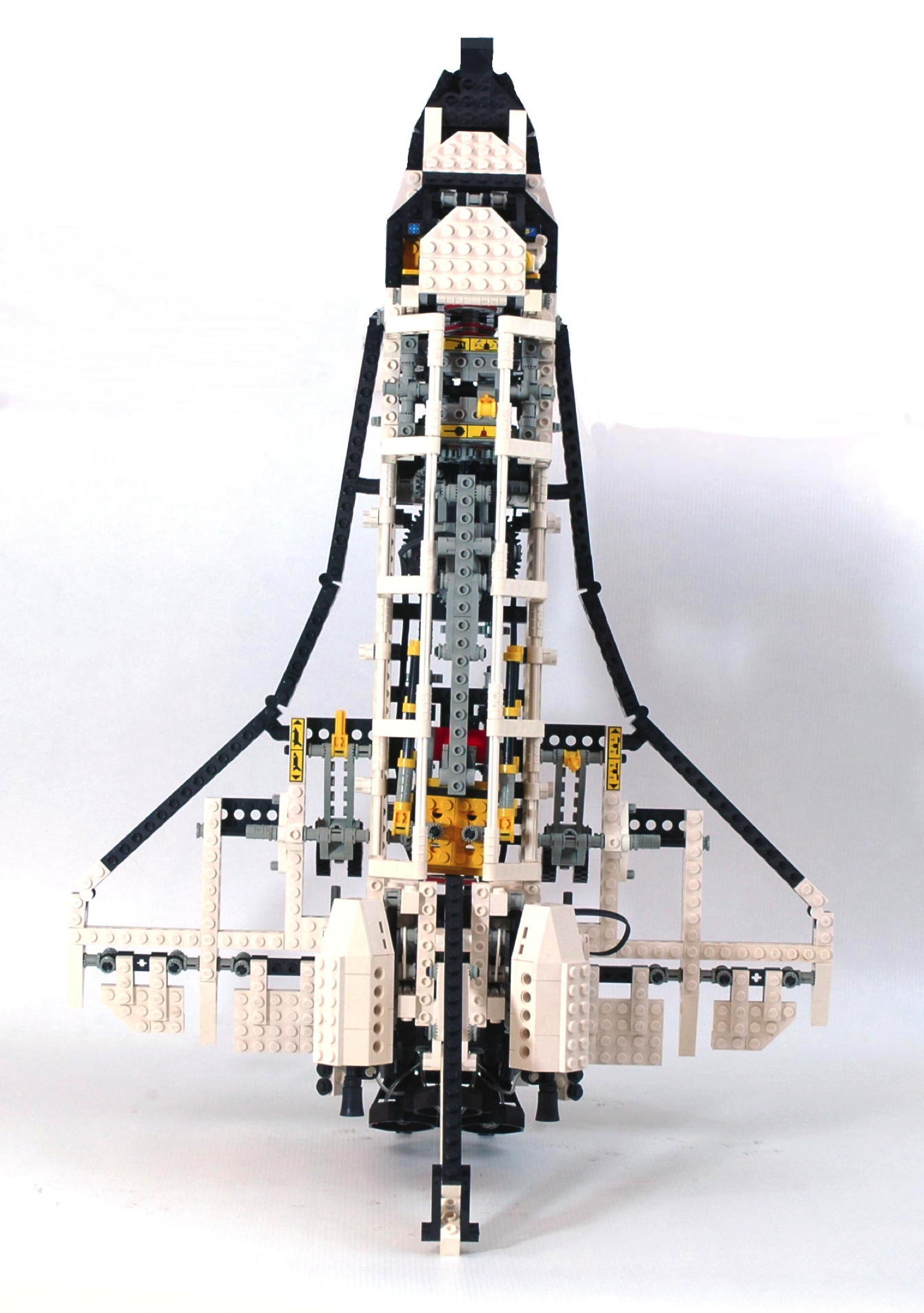
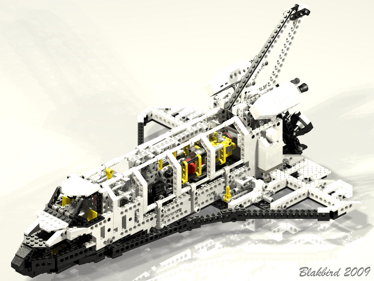
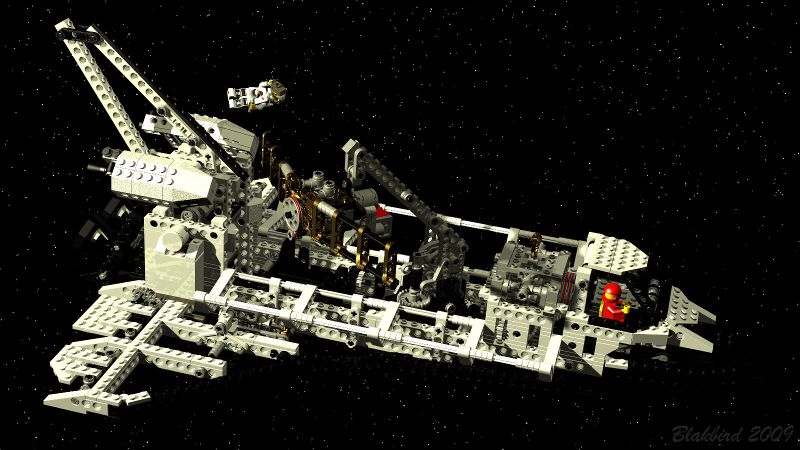
If there was any lingering doubt about what it is that makes 8480 so
great, these images should clear up the confusion nicely (make sure to
look at the full size versions). You can see that the insides of
the model are positively packed with mechanical and electrical
functions. In fact, the gearing is so dense that it is difficult
to see what is happening without dissecting the functions individually. This is precisely what will follow below.
|

 |
|
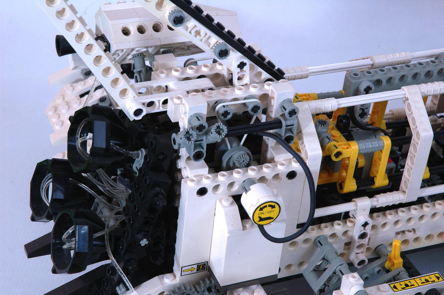
Electrical System
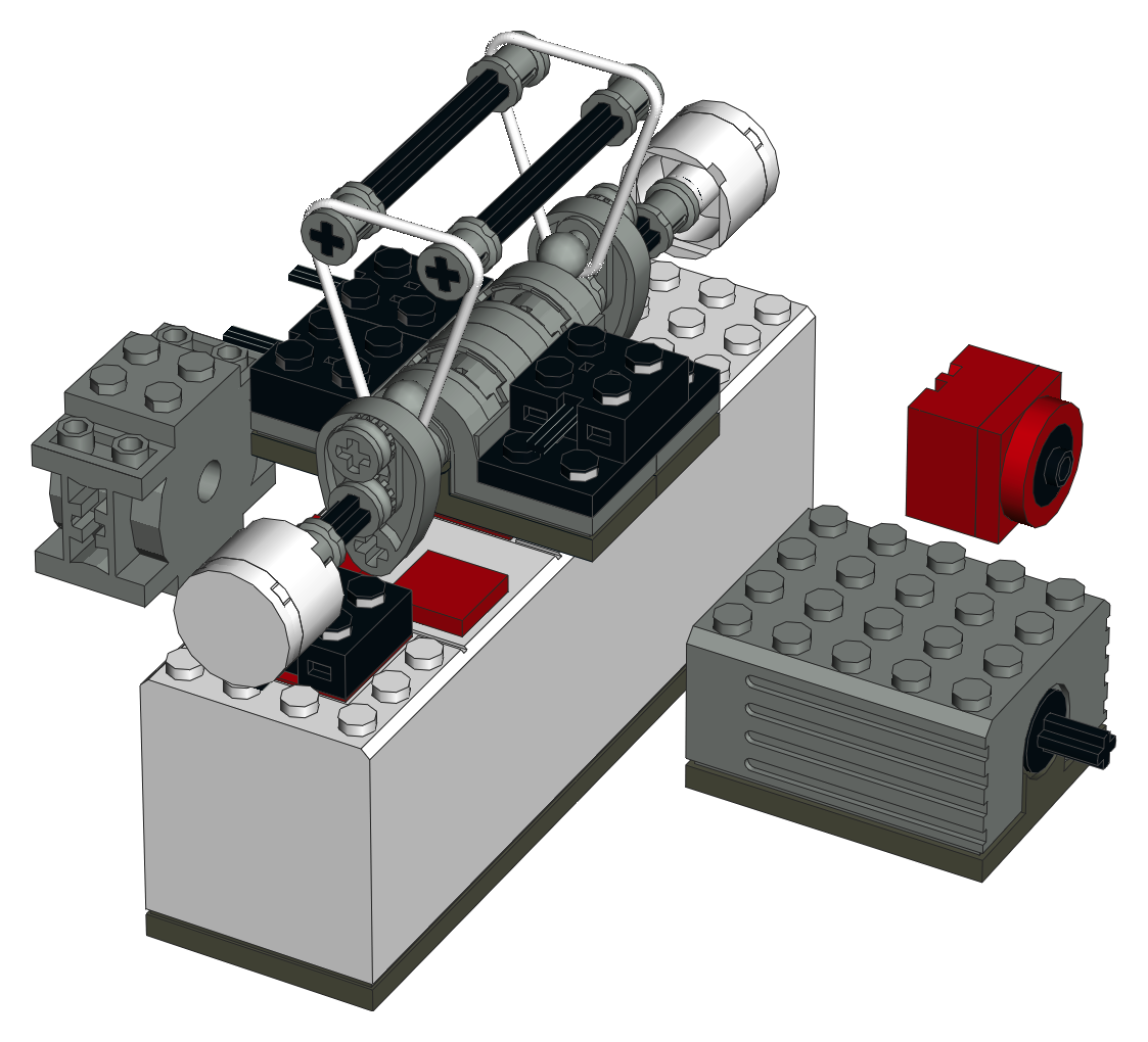
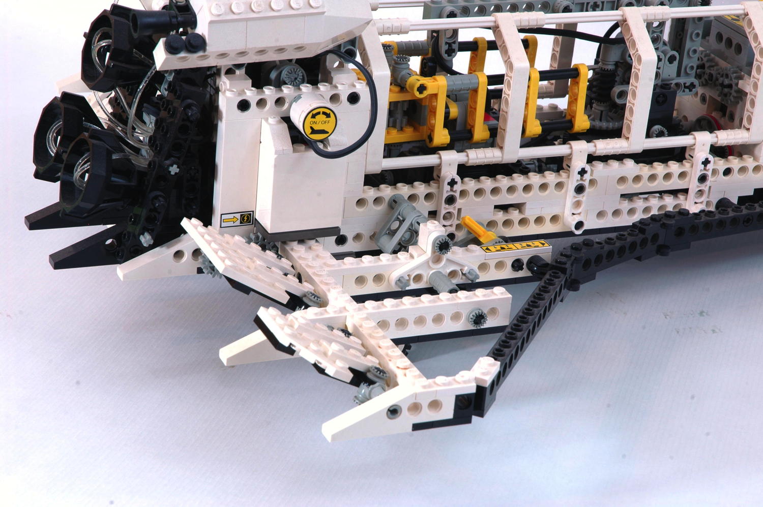
8480 features by far the most complex electrical system up to that time
with two motors, two switches, and a fiber optic system. A 9V
(6xAA) battery box is tucked away in the aft fuselage where it blends in
nicely and yet remains easily accessible. The battery output goes
to a 2x4 electrical plate which spans a pair of pole reversers.
These are used as both on-off switches and as a means to reverse the
polarity of the motors. An axle protruding from each switch is
accessible from outside the model and centered by a rubber band overhead
as seen in the computer image. Simply turn the round knob and a
motor runs as long as the knob is held. Release the knob and the
motor shuts down. Turn the knob the other direction and the motor
reverses. The knob on one side controls the main 9V motor which
runs the gearbox. The knob on the other side controls the micro
motor which is connected to the satellite. The fiber optic
box is wired to the same switch as the main motor, so it is illuminated
(but not turning) any time the main motor is running, regardless of direction.
The motors in the computer image are shown in a false location for ease
of display. They are actually located at the opposite end of the
model from the battery box and connected by very long wires which must
be painstakingly routed through the lower fuselage. The main motor
is nestled between the astronauts' seats.
|

|
|
Gearbox
The heart of the model is a 4 position gearbox. It uses the same basic principles as the pioneering gearbox in 8880,
but instead of being used to change gear ratios it is used to connect a
single input motor to one of four different output functions.
The first photograph shows the shift lever and gate with the 4
positions. Each function is marked with a sticker. As the
lever is moved through the H-shaped gate, one
or the other of the two driving rings is forced into position.
Note that only one driving ring can be engaged at a time. Passing
through the center of the H returns the opposite ring to center.
Whereas 8880 had a custom shift lever and mounting plate, the shuttle
uses a new pair of shift gates and lever which would become the standard
for the immediate future.
The driving ring is the key to everything. It slides over the
ridged axle joiner. Small tabs on the driving ring allow
it to lock along these ridges, but still slide with some extra
force. The driving ring grips the longitudinal grooves on the
axle joiner causing them to rotate together. A circumferential
groove in the middle of the ring allows it to be pushed along the axle
joiner in either direction. A set of 4 driving dogs on either end
then mate with a 16 tooth idler gear allowing the idler's rotation to
be either synched with the axle or allowed to spin freely.
The animation shows how the driving rings work to engage and
disengage the clutch/idler gears. The driving ring is shown in
red. The
lower axles are joined with the gray axle joiner. The driving
ring rotates with the axles. At first, the driving ring is
disengaged so both the dark gray and green gears are not driven and
slip on the axle. The driving ring then engages the green gear
and
thus drives the blue gear. Because the driving ring does not use
gear teeth but
rather uses four tapered driving dogs, there is considerable backlash
between the driving ring and the gear. The allows the driving
ring to be engaged even while it and the mating idler gear are turning
at different speeds.
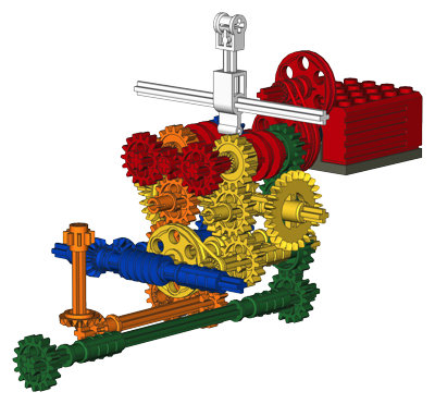
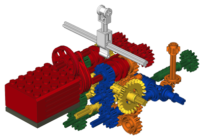
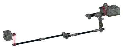
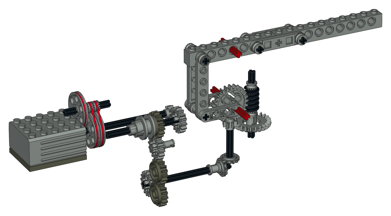
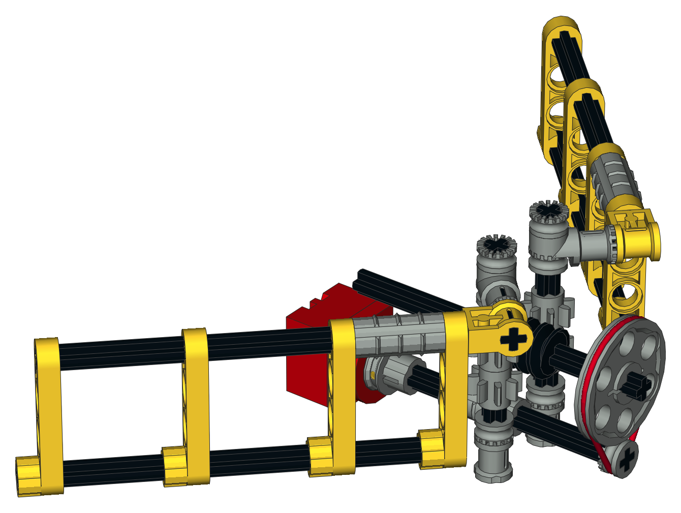
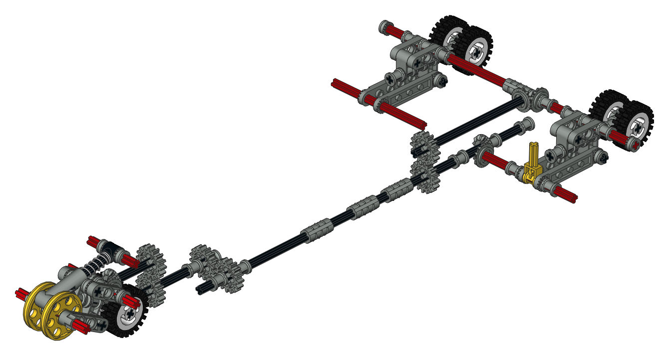
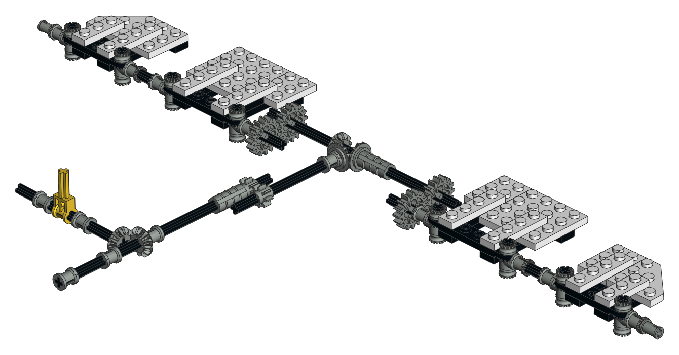
The lower computer images are color coded to show the different
gear paths for each of the 4 functions. Red is the input from the
motor which uses two stages of belts. This both reduces the
motor's speed 9:1 and allows slippage if any of the functions
stalls. The pair of red axles in the upper part of the image are
driven continuously by the motor. The white lever is used to
switch gears. Yellow is the door mechanism, blue turns the crane,
orange lifts the crane, and green runs the fiber optic engine. Any
of these functions individually is pretty complex, but making them all
fit together in such a small space with no interference is the real
achievement.
|

|
|
Doors
The cargo bay doors open when driven by the main motor. The doors
are synchronized to move together, although sometimes one or the other
can skip a gear tooth if too much resistance (like a finger) is present.
The computer image shows how the mechanism works. After the
initial belt reduction of the motor, there is still a lot more reduction
to come. The gearbox driving ring passes torque downward through
several levels of the gearbox via 16 tooth idler gears, then uses a belt
to provide another 3:1 reduction. Next a worm gear is used to
mate with a 24 tooth gear mounted laterally. This drives a pair of
crown gears which drive the 16 tooth gears mounted to each door.
The worm gear allows the door to maintain any position without
backdriving. Final reduction from the motor is 3:1 x 3:1 x
16:8 x 3:1 x 24:1 x 16:24 = 864:1 which drives the doors at a very reasonable speed.
Because this function has such a huge gear reduction, the use of the
additional belt further downstream from the motor provides an effective
torque limiting function.
|
Click for an animation of the cargo bay doors in motion. |
|
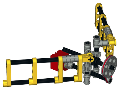
Arm Lift
The Remote Manipulator Arm can raise and lower using the same
motor. Since the arm can both lift and pivot, the lifting function
must pass concentrically through the turntable to the arm. The
whole arm only lifts about 45 degrees at full extension.
The computer image shows the torque path. After the initial belt
reduction of the motor, the gearbox driving ring passes torque downward
through several levels of the gearbox via 16 tooth idler gears. A
set of bevel gears then turns the corner and passes through the
turntable. A further 3:1 reduction happens with spur gears prior
to the worm gear. The vertical worm gear drives a 24 tooth gear
whose axle lifts the arm. It is a little tricky to picture how the
arm mechanism works, so I've color coded the axles which are grounded
to structure in red. The links pivot at these axes resulting in a
4-bar linkage.
Final reduction from the motor is 3:1 x 3:1 x 16:8 x 24:8 x 24:1 = 1296:1
|

Click for an animation of the arm lifting. |
|
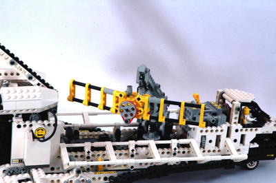
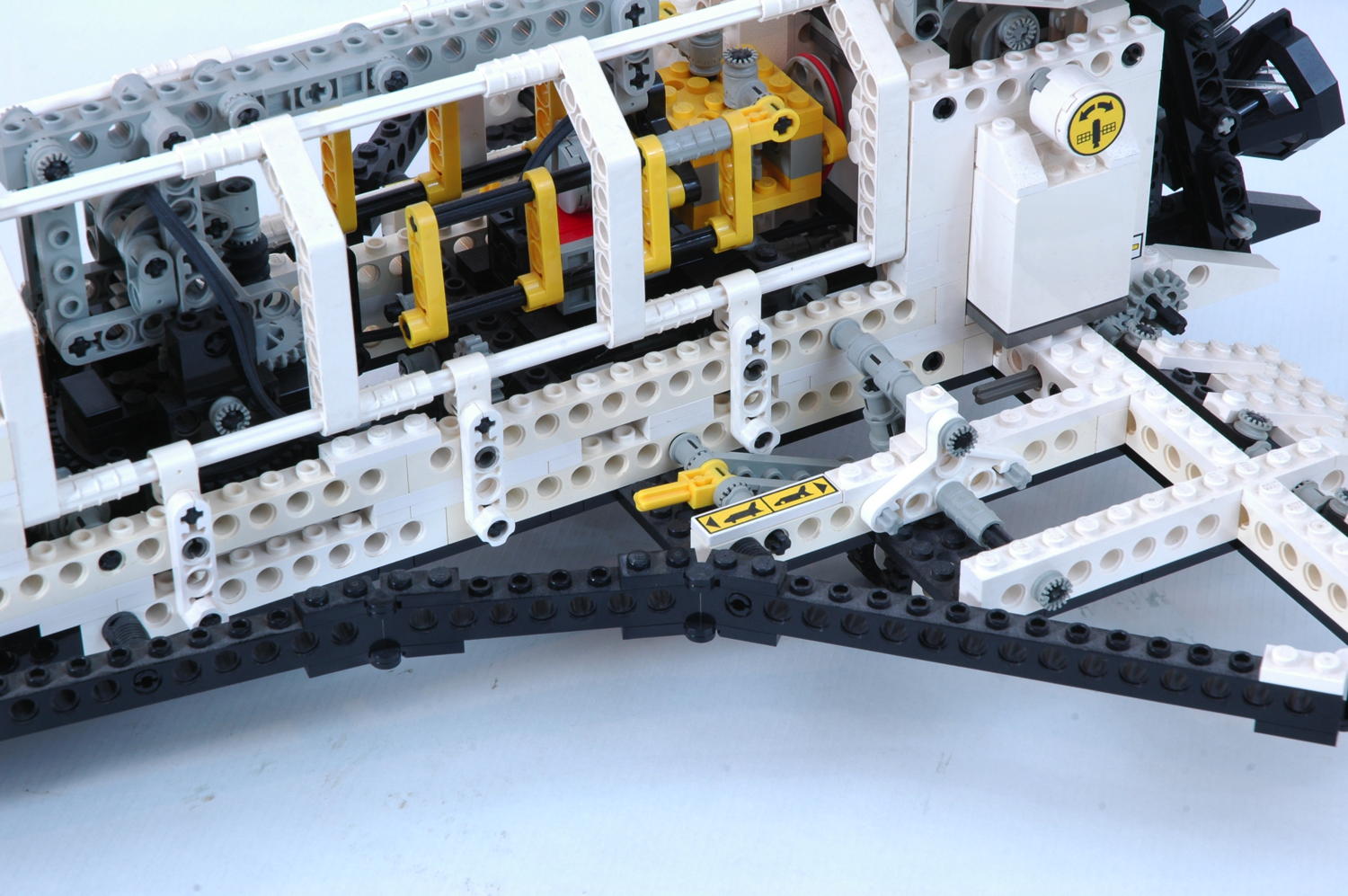
Arm Rotation
The Remote Manipulator Arm can also rotate on on a turntable driven by
the same main motor. It is capable of pivoting about 70 degrees
from center in either direction before the wire which runs up the arm to
the satellite becomes taut. There are also a pair of plates which
mechanically limit the rotation at ~90 degrees.
The computer image shows the torque path, the simplest in the
model. After the initial belt
reduction of the motor, the gearbox driving ring passes torque downward
through a level of the gearbox via a 16 tooth idler gear. A set
of bevel gears then turns the corner and drives the turntable with a
worm. Final reduction from the motor is 3:1 x 3:1 x 16:8 x 56:1 = 1008:1
|
Click for an animation of the arm rotating. |
|
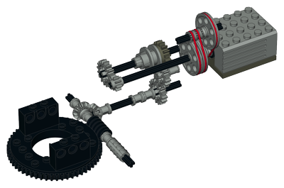
Satellite Deployment
The satellite hangs at the end of the arm and is driven by a micro
motor. The output pulley of the micro motor drives another pulley
through a 3:1 reduction (keep in mind the micro motor turns very slowly
to begin with). A worm gear then drives a pair of 8 tooth pinions
directly connected to the solar arrays of the satellite. Final
reduction is 3:1 x 8:1 = 24:1.
This is the slowest function of the model. Full deployment of the solar arrays takes about 10 seconds.
Because this function uses a separate motor not driven through the
gearbox and powered by a separate switch, it can be run simultaneously
with other functions. For example, it makes sense to have the solar arrays opening as the arm rotates.
|
Click for an animation of the satellite in motion. |
|
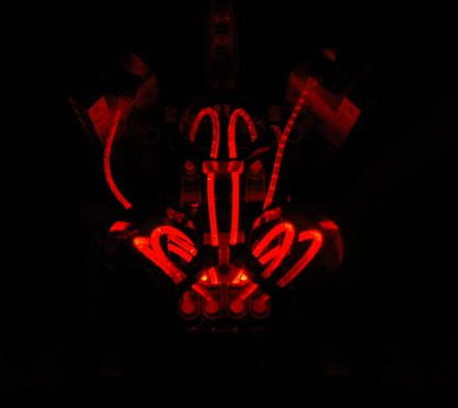
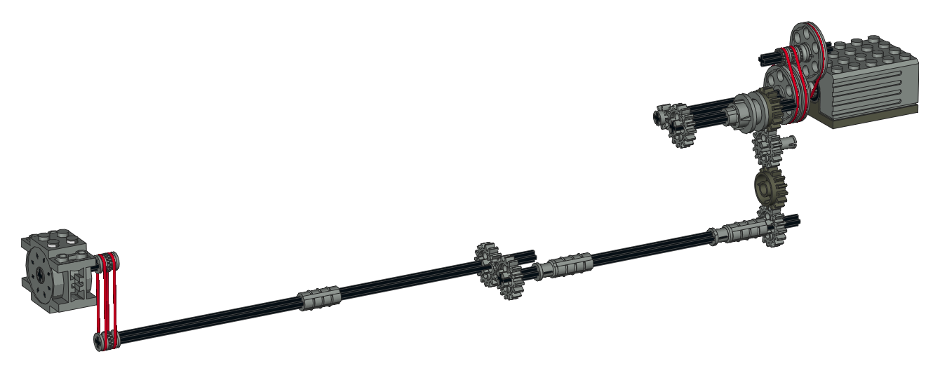
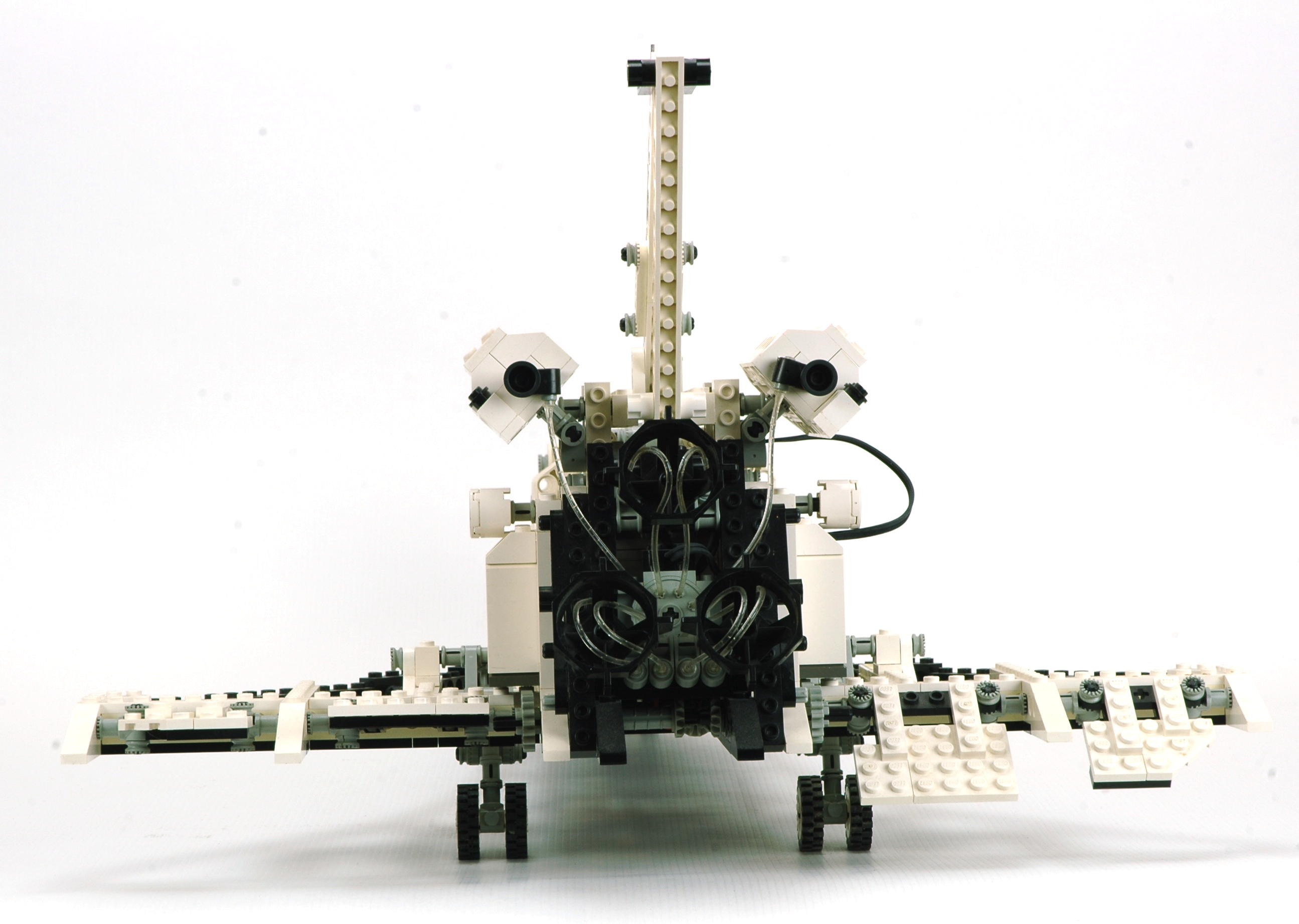
Engines
The engines use the new fiber optic system. While power is
available to the lights inside the unit any time the main motor is in
use, the unit only sequences the lights when the function is engaged at
the gearbox. After the initial belt reduction of the motor, the
driving ring passes torque downward
through several levels of the gearbox via 16 tooth idler gears before
making the long journey to the rear of the vehicle. A final 1:1
system of belts rotates the
fiber optic unit. Final reduction from the motor is 3:1 x 3:1
x 16:8 = 18:1 which drives the engines very quickly.
The fiber optics are not very bright and are certainly best appreciated
in the dark, though they are certainly also visible in the daylight.
From this angle you can see the 3 unique engine parts used for the
shuttle's main engines tilted slightly upwards. You can also see
the boosters on either side of the vertical tail.
|

Click for an animation of the engines in motion. |
|
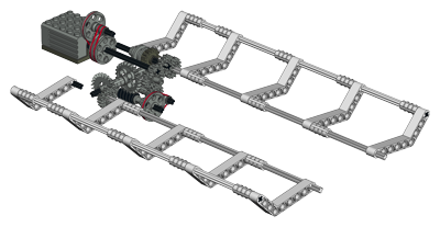
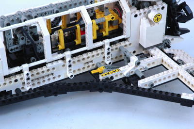
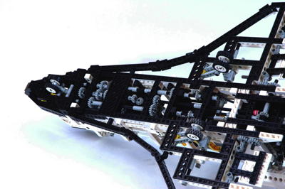
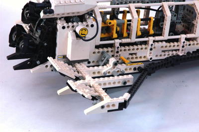
Landing Gear
Although it is not motor driven, the landing gear is probably the most
mechanically complex feature of the model. The input is a yellow
lever on the port wing, but the spring which holds the whole system
either up or down is way up in the nose wheel well. The images at
the bottom show the gear in both the up and down positions. Note
that on this model even when the gear is up it still protrudes slightly
from the bottom of the vehicle and therefore still provides
support. When extended, the gear holds the vehicle up higher and
with a slight nose down angle, just like the real shuttle.
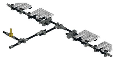
The computer image color codes all the axles which are supported by
structure in red as an aid to understanding the mechanism. The
spring in the nose gear passes over center and therefore holds the gear
against the stops in either the up or down position. The up stop
is a pair of 3L dark grey axle above the main gear, and the down stop is within the nose gear linkage.
The yellow lever rotates a lateral axle which then drives a longitudinal
axle running the length of the vehicle through a set of bevel
gears. At the aft end, a lateral axle drives the links which lower
the main gear. At the forward end, a more complicated 4-bar
linkage pivots the nose gear down. Both gear lock in such a way
when deployed that the weight of the model is transmitted directly into
structure and not through the gear train. It is a mechanism which
must really be seen in motion to be fully appreciated.
|

Click for an animation of the landing gear in motion. |
|
Ailerons
Last but least are the functional elevons. The elevons in the real
shuttle act in two different but interconnected ways. As
ailerons, they move in opposite directions on each wing for roll
control. As elevators, they move in the same direction on each
wing for pitch control. The elevons on the model function only as
ailerons.
A yellow lever on the starboard wing drives the ailerons via a 1:1
linkage as shown in the computer image. Care must be taken while
building to get the gears synchronized so all the control surfaces are level at the same time.
|
Click for an animation of the ailerons in motion. |


