Features
|
|
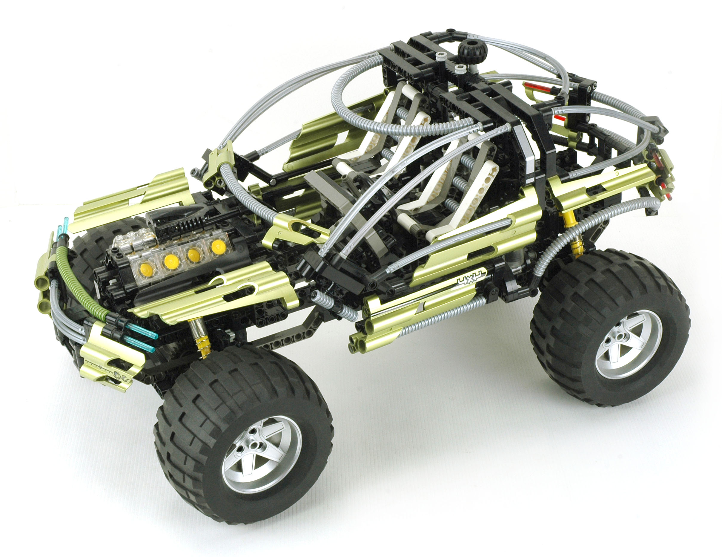
Similarity to 8448
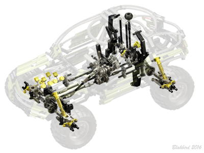
Although superficially much different, this model shares much with the 8448 Super Street Sensation from 1999.
They both have the same 5 speed plus reverse transmission, 4 wheel
independent suspension, and damped gull-wing doors. The primary
difference is that this model adds 3 differentials for 4 wheel drive.
|
|
|
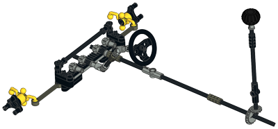
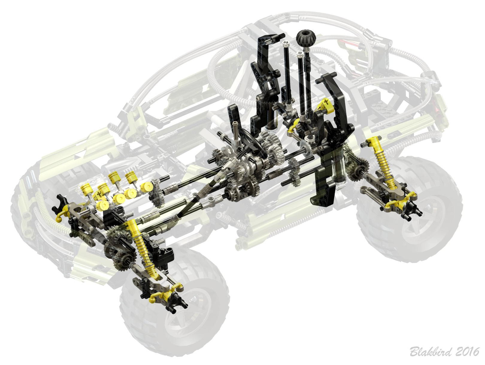
Steering
The front wheels are steerable with a rack and pinion system. An
overhead "Hand of God" wheel serves as input and then drives through a
set of bevel gears. The rack is guided by a lateral axle and held
down by a pair of other pinion gears. The rack is connected to tie
rods going out to the
steering knuckles.
Note that these steering new hubs do NOT include Ackerman
correction. This is a bit surprising given the otherwise complex
model and the fact that there is plenty of room inside the deep wheels.
A 4th pinion gears pulls power from the rack to backdrive the steering
wheel through a universal joint. Alternatively, the steering wheel
can be used as input. Is turns about 180° lock to lock.
|
Click for an animation of the
steering in motion.
|
|
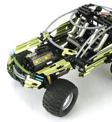
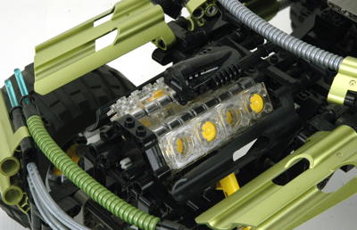
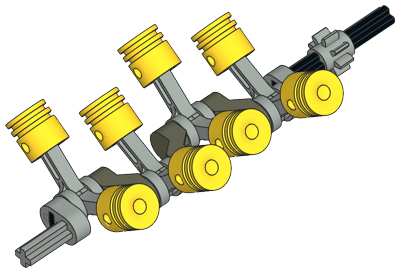
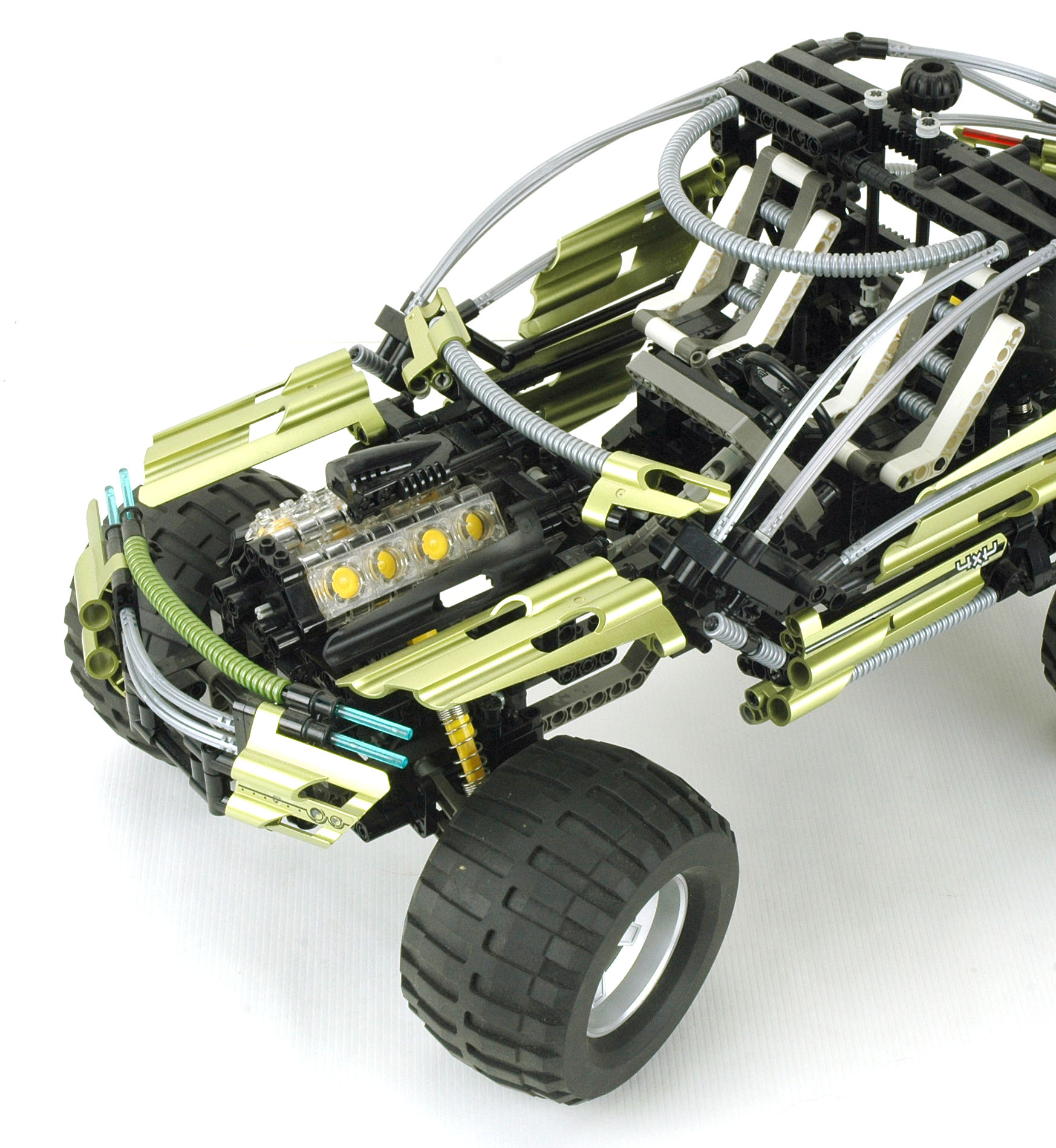
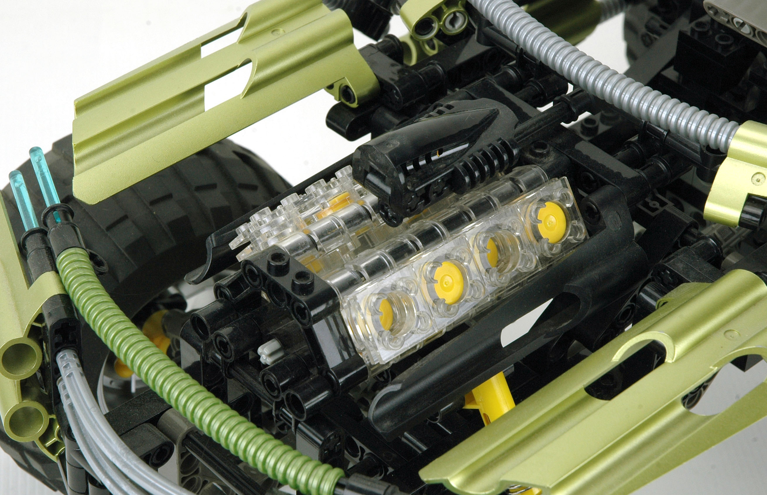
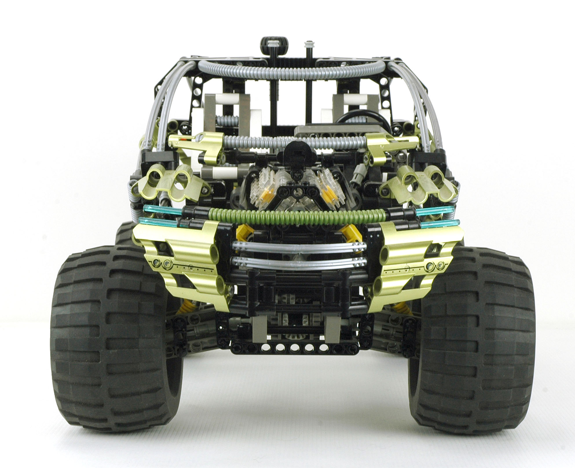
Engine
This set features a front mounted V-8 engine. The engine is made from clear cylindrical engine elements
and is driven by the all 4 wheels.
The crankshaft is
offset 1/2 stud from center, giving the pistons a stroke of 1
stud. The crank has 4 crank pins at 180 degree angles. Most
V-8s have crossplane cranks with the pins at 90 degrees. While
many racing V-8s do indeed have flatplane cranks like this LEGO
version, they are always 0-180-180-0 instead of 0-180-0-180.
The engine also uses a Bionicle part as an intake
manifold or supercharger ram.
|
Click for an animation of the
engine
in motion.
|
|
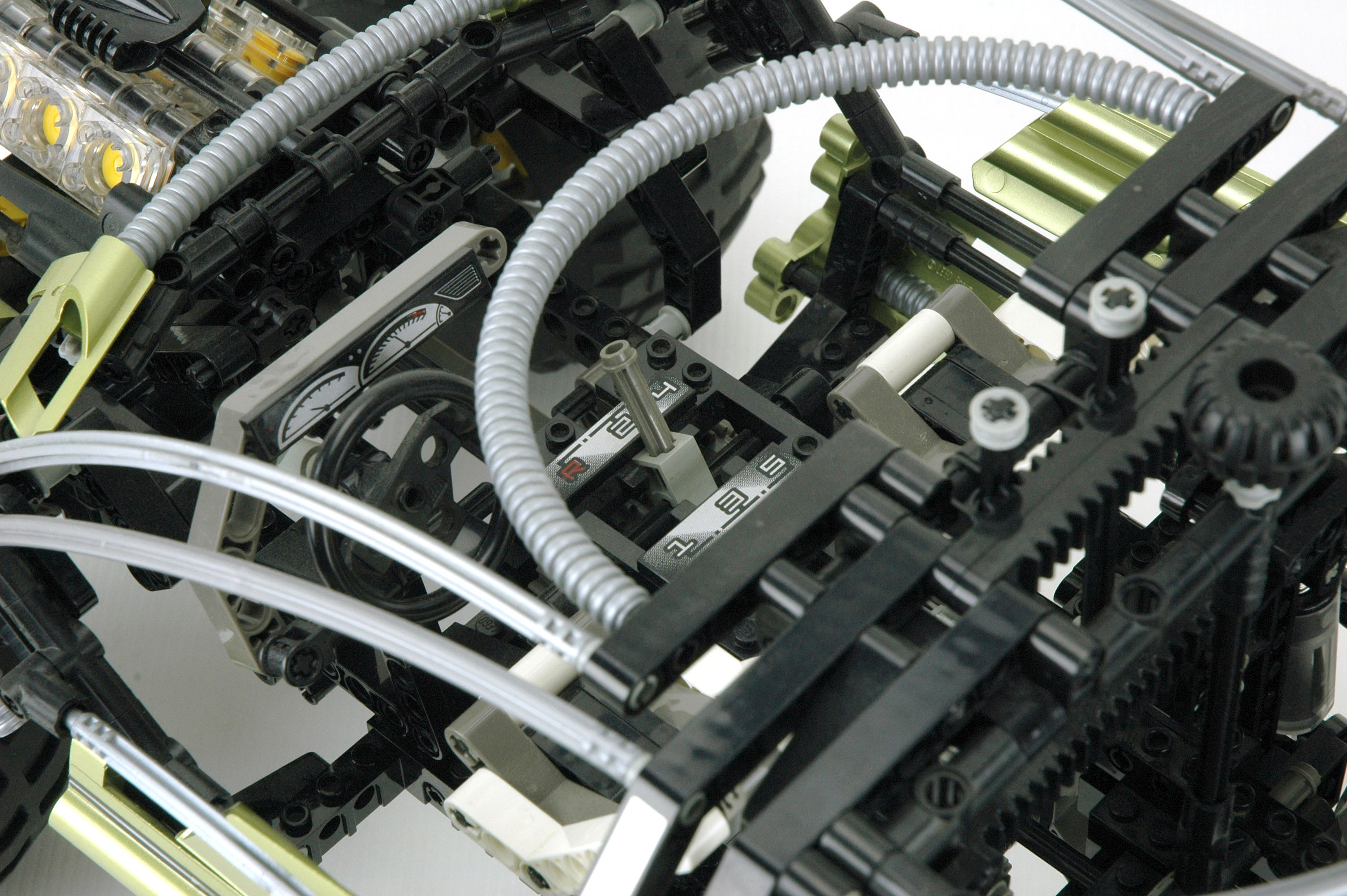
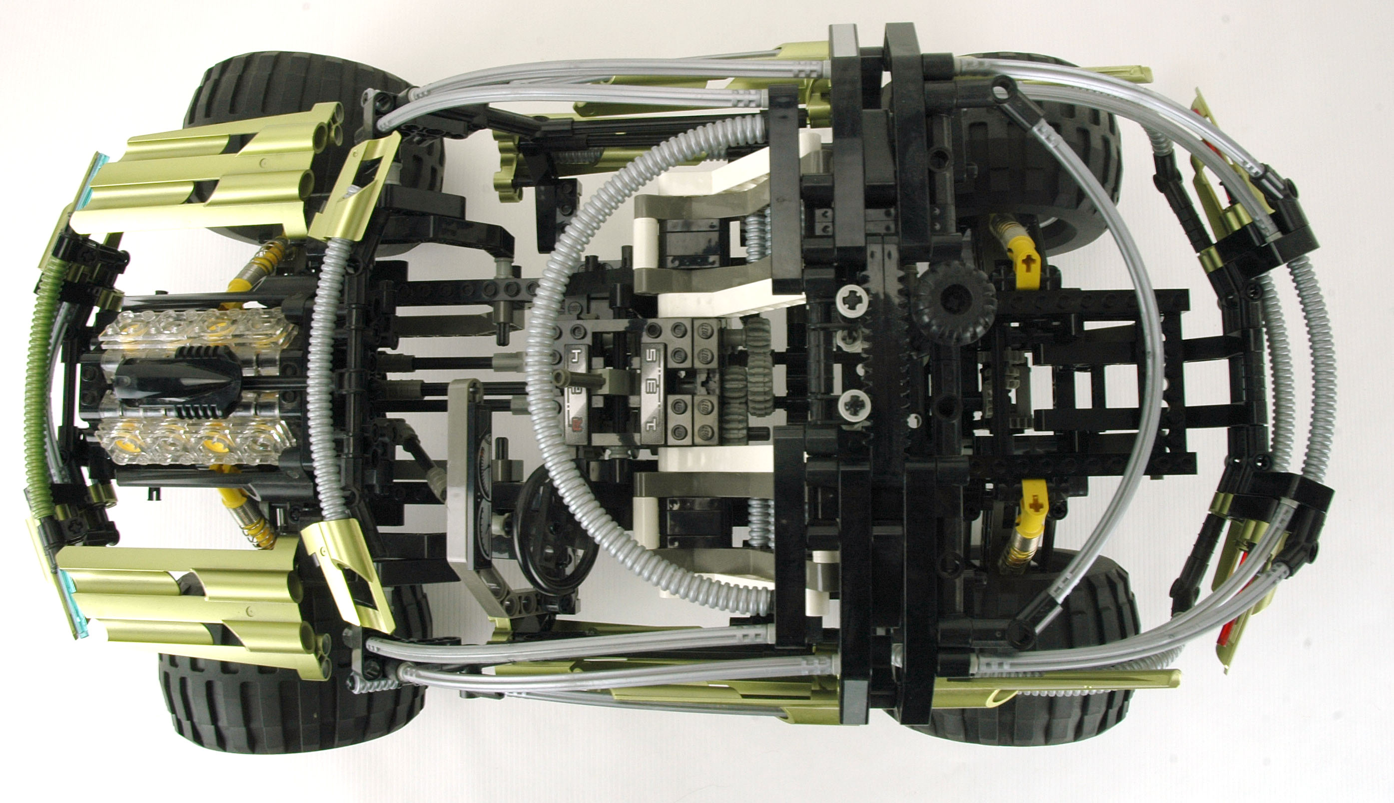
Transmission
The transmission is located between the seats. As a synchronized unit, this
one does not need to be aligned to shift and can even be shifted while
rotating.
The photograph shows the shift lever and gate with the 6
positions. As the lever is moved through the H-shaped gate, one of the three driving rings is forced into position.
Note that only one driving ring can be engaged at a time. Passing
through the center of the H returns the opposite ring to center.
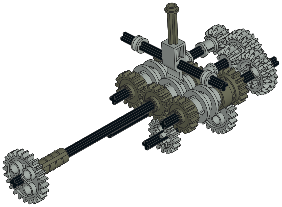
The driving ring is the key to everything. It slides over the
ridged axle joiner
which we first saw in 1993. Small tabs on the driving ring allow
it to lock along these ridges, but still slide with some extra
force. The driving ring grips the longitudinal grooves on the
axle joiner causing them to rotate together. A circumferential
groove in the middle of the ring allows it to be pushed along the axle
joiner in either direction. A set of 4 driving dogs on either end
then mate with a 16 tooth idler gear allowing the idler's rotation to
be either synched with the axle or allowed to spin freely.
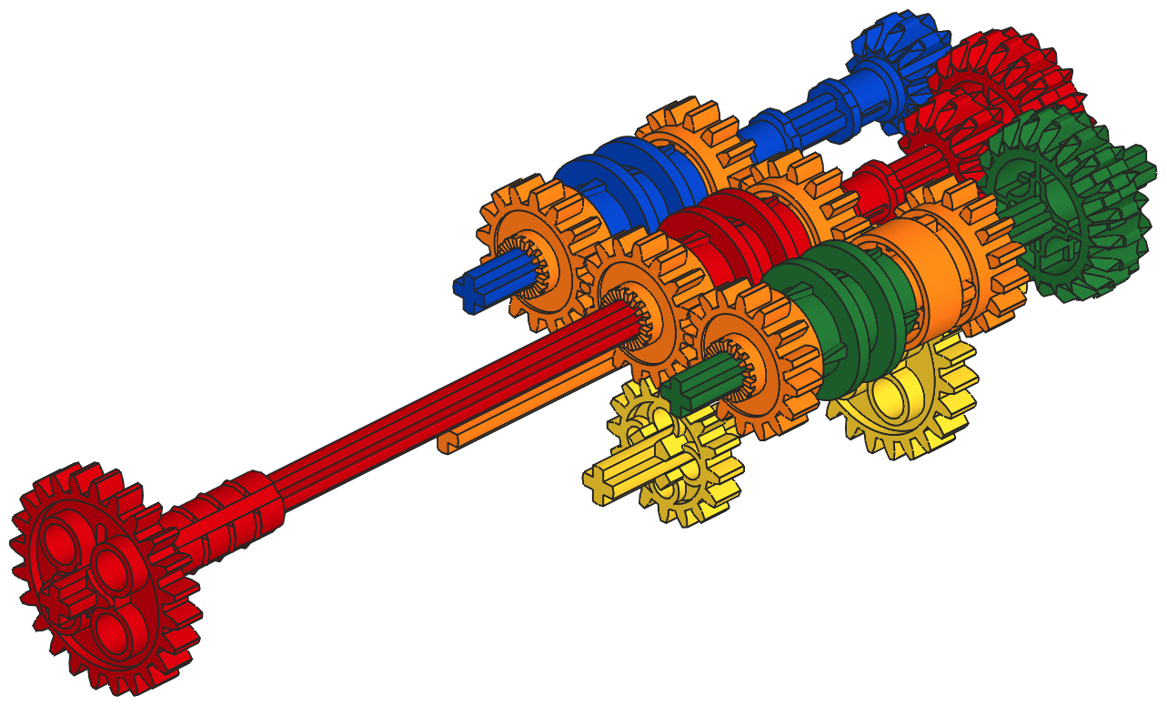
The animation shows how the driving rings work to engage and
disengage the clutch/idler gears. The driving ring is shown in
red. The
lower axles are joined with the gray axle joiner. The driving
ring rotates with the axles. At first, the driving ring is
disengaged so both the dark gray and green gears are not driven and
slip on the axle. The driving ring then engages the green gear
and
thus drives the blue gear. Because the driving ring does not use
gear teeth but
rather uses four tapered driving dogs, there is considerable backlash
between the driving ring and the gear. The allows the driving
ring to be engaged even while it and the mating idler gear are turning
at different speeds.
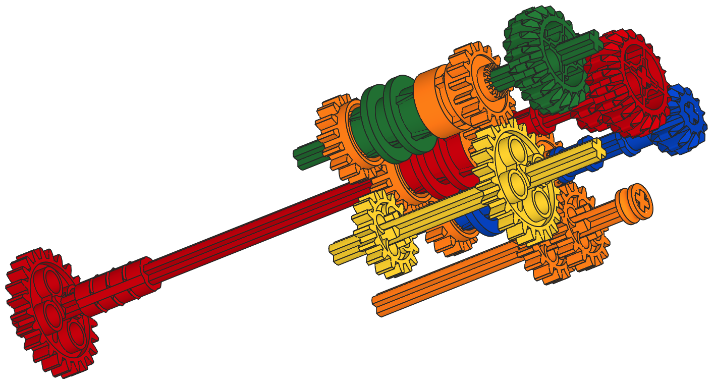
The computer images are coded to show the different
gears paths for each of the 6 gears. The red parts go to the
engine. The yellow 16 tooth gear is the output to the center
differential ring gear. You can see that the red axles interface
with
the other gears in two places: blue and green. This means that
the red, blue, and green axles are always turning at different
rates. The front orange row of 16 tooth idler gears mates with a
16 tooth yellow output, while the rear orange row of idlers mates with
the yellow 24 tooth gear. This results in a total of 6
combinations depending on which driving ring is engaged, with the driving ring extension producing reverse.
|
|
|
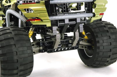
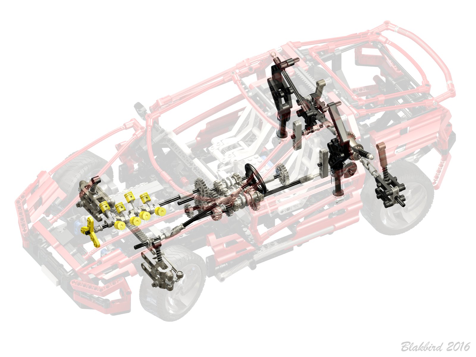
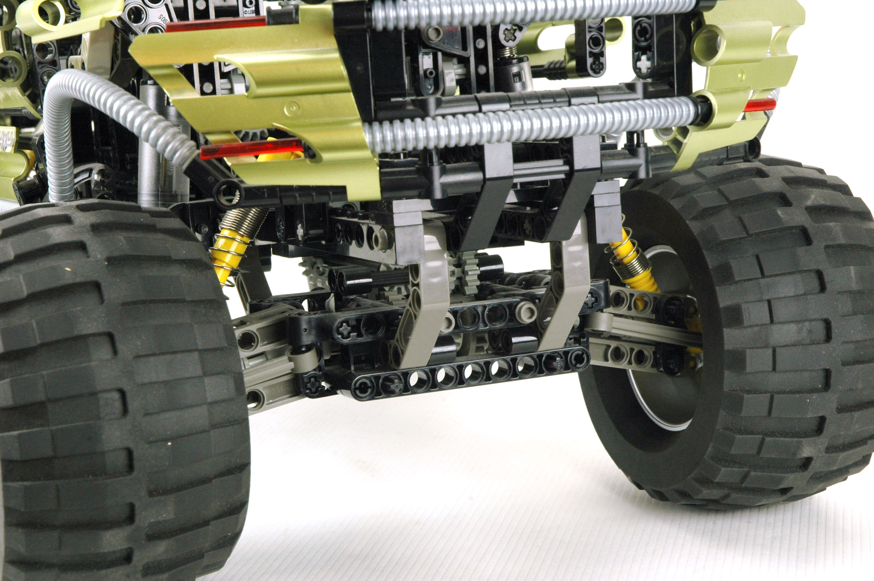
Suspension
All 4 wheels have independent suspension.
The front and rear suspension are nearly identical standard double wishbone type. Because it is a
four bar linkage, the wheel stays perpendicular to the ground
throughout its travel. A set of large shock absorbers provide huge ground clearance and travel.
The front suspension adds steering, while the tie rods on the rear hubs are simply grounded to structure.
All four wheels are also driven via constant velocity (CV) joints connected to the inside of the hubs.
The suspension on this model is quite soft. The front suspension depresses about half way under the
weight of the model, which is exactly as it should be. This means
the shocks can both extend or compress from neutral.
|
Click for an animation of the suspension
in motion.
|
|
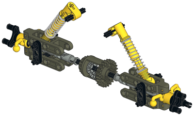
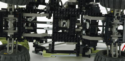
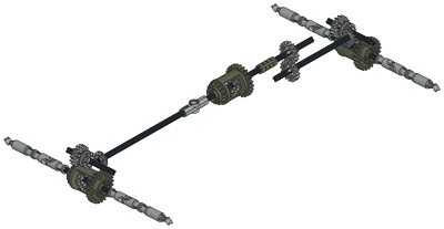
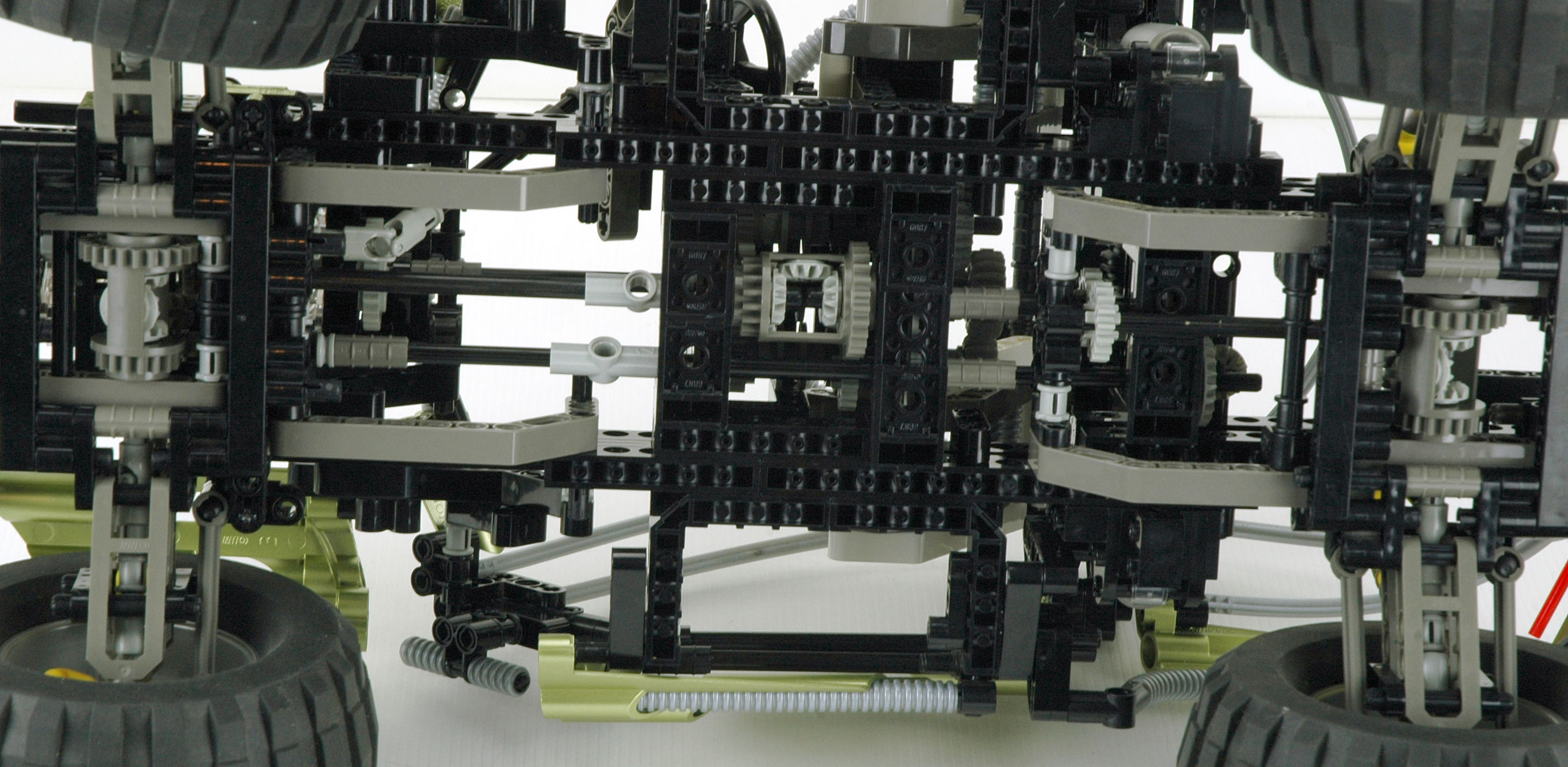
Driveline
This set 3 open differential gears: front, rear, and center.
Each
incorporates a built in 16 and 24 tooth ring gear, either of which work
as a spur.
In this case the smaller 16 tooth is used on the center diff which is
driven by the transmission. Each differential is made
to house 3 of the 12 tooth bevel gears. One is on each axle,
and one planet gear in the middle allows the axles to turn at different
rates.
There are no locking differentials here, although the differential part does include a slot for adding this feature.
|
Click for an animation of a
differential
in motion.
|
|
Gull Wing Doors
The gull-wing doors use a fascinating damped mechanism, and is coupled
to a extensible running board for ease of entry into this high
vehicle. A bushing on top serves as a trigger. Pushing the ball
down turns a vertical crank which pushes a slider into the
damper, forcing it over center. At this point, the spring slowly
lifts the door and the linkage that lowers the stop. The red axles
in the computer image are rotation points fixed to structure.
Make sure to watch the animation because it is quite mesmerizing.
|
|
|
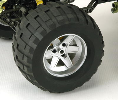
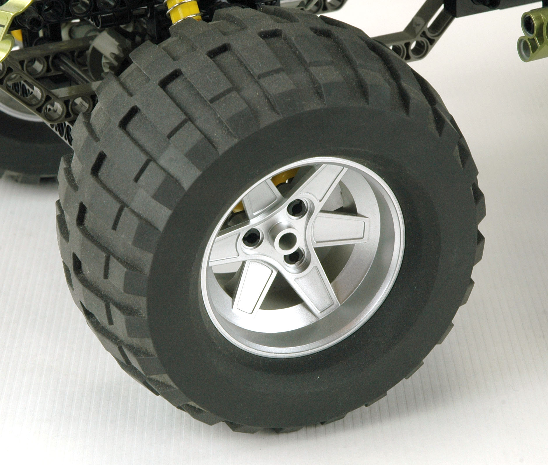
Wheels and Tires
This model uses a set of the huge Power Puller tires from 8457,
the only other model to ever include them. Unlike the tires from
that model, these are not marked. These huge balloon tires are
very
soft and "grippy" and deform significantly under torque like real power
puller tires. This creates a lot of rolling resistance, but it sure looks good!
|
|


