
Technical Fundamentals
Gears
Fundamentally, gears are devices which transmit rotational motion from
one axis to another. Certain types of gears may also result in
translational motion. There are dozens of different types of
gears in industry, only a few of which are replicated in LEGO®.
The
existence
of
LEGO® gears actually
predates the
Technic or Expert
Builder lines and goes back to the Samsonite gear wheels of the
1960's. The different types of LEGO® gears and
their basic
function and usage will be explained below.
Gear Ratios
In the simplest case, a set of gears
results in the same rotation speed on both the input and the
output axle. This happens if both gears have the same number
of teeth. However, in most cases gears are used to change the
speed and mechanical advantage between axles. For simple gears
like those used in LEGO®, calculating
this gear ratio is
simply a matter of counting the number of teeth on each gear and
comparing by dividing the number of output teeth by the number of input
teeth. For example, if the input gear has 8 teeth and the output
gear has 24 teeth, then the gear ratio is 24/8 = 3. The standard
nomenclature for this is to use a colon and relate the gear ratio to
one, for example 3:1.
So what does it mean to have a gear ratio of 3:1? Firstly, this
is the ratio of the rotational speeds of the axles. The gear with
fewer teeth always rotates faster, so in this example the 8 tooth gear
rotates 3 times faster than
the 24 tooth gear. Secondly, the ratio of torque is the inverse
of this ratio. In this example, the 8 tooth gear has 3 times less torque than the 24 tooth gear.
When you use gears to make something rotate faster and produce less
torque, it is called "gearing up". You might use this to
protect
downstream components from the high torque of a motor. When you
use gears to make something rotate slower
and produce more torque,
it
is
called
"gearing
down".
You
might use this to lift something
heavy with a small motor or crank. Sometimes you might not gear
up or down, but simply use gears to get torque from one point to
another with no change in speed or torque.
Spur Gears
Spur gears operate on axes which are
parallel. In the animation below, the gray 16 tooth gear on the
green axle is driving the red 24 tooth gear on the yellow axle.
Note that the relative speeds are 3:2 which is the ratio of their
number of teeth (24:16). Note also that the contour of the gear
teeth is not flat. The profile used is called an involute and it allows the gear
teeth to roll against each
other rather than slide which
minimizes
friciton
and
maximizes
efficiency.
Also note that each
axle has two Technic bricks used as bearings for support. In
general, you want at least 2 bearings supporting each axle to balance
the gear tooth loads, although it is possible to use just one axle pin
with reduced efficiency. The closer you can locate the bearing to
the gear (like the black brick), the more efficiently it will provide
support. It is also generally better to locate bearings on either
side of the gear (like the blue bricks) than to put them both on one
side. One side effect of a pair of spur gears is that the output
axle rotates the opposite direction as the input axle, an effect which
can be clearly seen in the animation. Spur gears are the most
common gear type in Technic.

There were some spur gears made before Technic and Expert Builder even
existed in the 1960's and 1970's, but those are not covered by
Technicopedia. They were very large and ranged from 9 to 42 teeth.
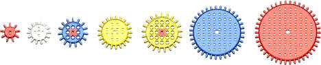
The image below shows the "standard" spur gears. The three shown
in light gray (8 tooth, 24 tooth, and 40 tooth) existed from the
beginning in 1977 and are still in production. The 16 tooth shown
in tan came out in 1979. The 24 tooth shown in dark gray was a
stronger replacement for the older 24 tooth beginning in 1998.
The 24 tooth shown in white is a "clutch" gear which can slip
once a certain torque is exceeded. It is rare and was first seen
in 1997. All of these use the same tooth profile so any spur gear
can be used with any other spur gear. Note also that all tooth
counts are a multiple of 8 which makes gear ratio calculations easy.
Finally, the "double bevel" gears can also be used as spur gears.
These will be explained further in the section on
bevel
gears. They have wider teeth than the regular spur gears and
can handle more torque.
Bevel Gears
Bevel gears operate on axes which are
not parallel. Bevel gears can be made specifically for axles at
virtually any angle, but LEGO
® bevel
gears are all made
for perpendicular axles (90 degrees). In the animation below, the
red gear on the
yellow axle is driving the blue gear on the green axle. The axles
are turning at the same speed because the gears have the same number of
teeth. Bevel gears have complex tooth shapes which also generate
complex forces on the supporting axles. Therefore, it is even
more important than for spur gears that there are proper bearings for
support of the axles. In
general, you want at least 2 bearings supporting each axle to balance
the gear tooth loads, although it is possible to use just one axle pin
with reduced efficiency. The closer you can locate the bearing to
the gear, the more efficiently it will provide
support. In the animation, a special gearbox is used specifically
for this purpose. Spur gears are the second most common gear
type in Technic.

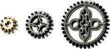
The image below shows the basic bevel gears. The light gray 14
tooth bevel gear was introduced in 1980 and used for many years,
including as part of the old
differential
assembly. In 1995 it was replaced with the 12 tooth bevel gear
shown in tan. This gear has a web between the teeth and it is
therefore much stronger and was used in the newer
differential.
The
uncommon
20
tooth
bevel gear shown in dark gray was
introduced in 1999.
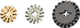
The double bevel gears shown below are so titled because the teeth are
beveled on both sides on the face of the gear. This makes them
somewhat more versatile than the regular bevel gears, but they are also
twice as thick and therefore take up more space. They come in 3
sizes: 12 tooth, 20 tooth, and 36 tooth and began to be introduced in
1999.
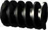
Worm Gears
A worm gear (or screw) can be thought
of as a gear with a single tooth. The LEGO
®
worm gear
operates on an axle which is perpendicular to a mating spur gear.
Worm gears have some special properties which make them differ from
other gears. Firstly, they can achieve very high gear reductions
in a single stage. Because the worm gear has only one tooth, the
gear ratio is simply the number of teeth on the mating gear. For
example, a worm gear mated with a 40 tooth spur gear has a ratio of
40:1. Secondly, worm gears have much higher friction (and lower
efficiency) than the other gear types. This is because the face
of the worm gear's tooth is constantly sliding across the teeth of the
mating gear. This friction gets higher the more load is on the
gear. Finally, worm gears cannot (generally) be backdriven.
In the animation below, the worm gear on the green axle is driving the
blue spur gear on the red axle. But if you turn the red axle as
an input, the worm gear will not turn. This is useful for locking
things in place like using a crank to raise and lower a lift
gate.
One final thing to remember about worm gears is that there is force
created which pushes the gear along the axle (green axle in the
animation). Something needs to be used to prevent this motion or
the gear will slide away. One possibility is the yellow gearbox
in the animation.

The worm gear is a little less than 2 studs long. Multiple worm
gears can be put in a row to make a longer screw. It is even
possible to mate a worm gear with the rack gear, although the fit is
not quite right.
Rack Gears
A rack gear is like a spur gear that
has been unrolled to lie flat. It is a means of transforming
rotational motion from the mating spur or pinion gear to translational
motion of the rack. A the pinion rotates, it pushes the rack gear
along as subsequent teeth mesh. There is no gear ratio in the
traditional sense, but the fewer the teeth on the driving gear the more
power will be delivered to the rack. The lateral movement of the
rack is proportional to the number of teeth on the pinion. These
gears are most traditionally used for vehicle steering, but have many
other uses including the extension of a telescoping boom on a crane.

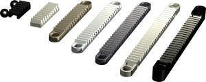
The gear racks range widely in size. The most common size is 4
studs long and attaches to a plate via studs. These can be placed
end to end to create a longer rack. There are a series
of even length racks (8, 10, 12, 14) which have pin holes at the end
and are open underneath so they can slide along studs. There is a
small 2.4 stud length rack with ball joints in the front.
Finally, there is a 13 stud long rack with perpendicular axle joiners
at the end (shown in black).
Differential Gears
Section in work

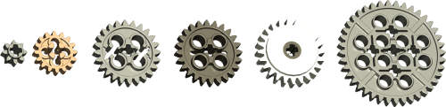
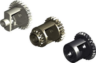
There have been 3 different differential gear carriers available over
the years. The one shown in light gray was released in 1980 and
was typically used with the old 14 tooth bevel gears. The ring
gear had 28 teeth. It was replaced by the one shown in old dark
gray in 1994. This was typically used with the 12 tooth bevel
gears. The large ring gear had 24 teeth at the large end and 16
teeth at the small end. It also had a recess for a driving
ring. The last version shown in new dark gray was released in
2008. It has a 28 bevel teeth on its ring gear and is used with
the 12 tooth bevel gears.
Driving Rings
The driving ring, in combination with a
pair of idler gears which do not turn with their axle of support, allow
functions to be engaged or disengaged. It slides over the
ridged axle joiner
which we first saw in 1993. Small tabs on the driving ring allow
it to lock along these ridges, but still slide with some extra
force. The driving ring grips the longitudinal grooves on the
axle joiner causing them to rotate together. A circumferential
groove in the middle of the ring allows it to be pushed along the axle
joiner in either direction. A set of 4 driving dogs on either end
then mate with a 16 tooth idler gear allowing the idler's rotation to
be either synched with the axle or allowed to spin freely.
The animation shows how the new driving rings work to engage and
disengage the clutch/idler gears. The driving ring is shown in
red. The
lower axles are joined with the gray axle joiner. The driving
ring rotates with the axles. At first, the driving ring is
disengaged so both the dark gray and green gears are not driven and
slip on the axle. The driving ring then engages the green gear
and
thus drives the blue gear. Because the driving ring does not use
gear teeth but
rather uses four tapered driving dogs, there is considerable backlash
between the driving ring and the gear. The allows the driving
ring to be engaged even while it and the mating idler gear are turning
at different speeds.

A fairly small number of sets have contained these parts over the
years. It is generally used either in a transmission used for
gear changes or in a gearbox used to select between multiple motorized
functions. The driving ring originally always light gray but has
more recently been typically red.
Adjustable Pitch Rotor
Section in work

Ackerman Rack and Pinion Steering
Section in work

Suspension
Section in work
Trailing Arm Suspension
Section in work
Double Wishbone Suspension
Section in work

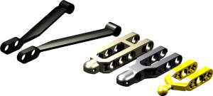
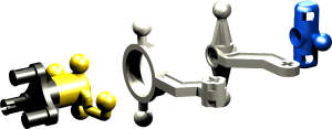
Many parts can be used to create the
upper and lower control arms including simple beams and liftarms, but
there are also a number of special purpose parts available. The
long Formula-1 style links shown in black first appeared in 2000, but
these appeared in only a few sets. The left dark gray control arm
appeared in 1988 and was replaced with the one on the right in
2008. The arm shown in yellow has appeared in a large number of
sets since 1994.
A number of special hubs have appeared over the years with ball joints
at the king pins and with additional provisions for a steering
attachment. The two in the center were only available in a single
set each, a
Supercar (
8880
and
8865).
The others are easier to find and the yellow one on the left also
supports connecting a driven axle to the hub with a constant velocity
joint.
4-Bar Linkage
Section in work
Engines
Original (Square Piston)
Section in work
Revised (Round Piston)
Section in work
