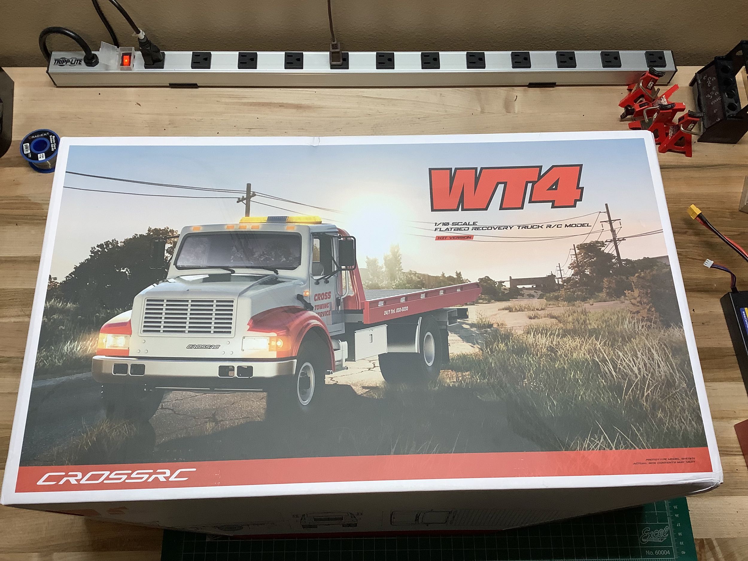
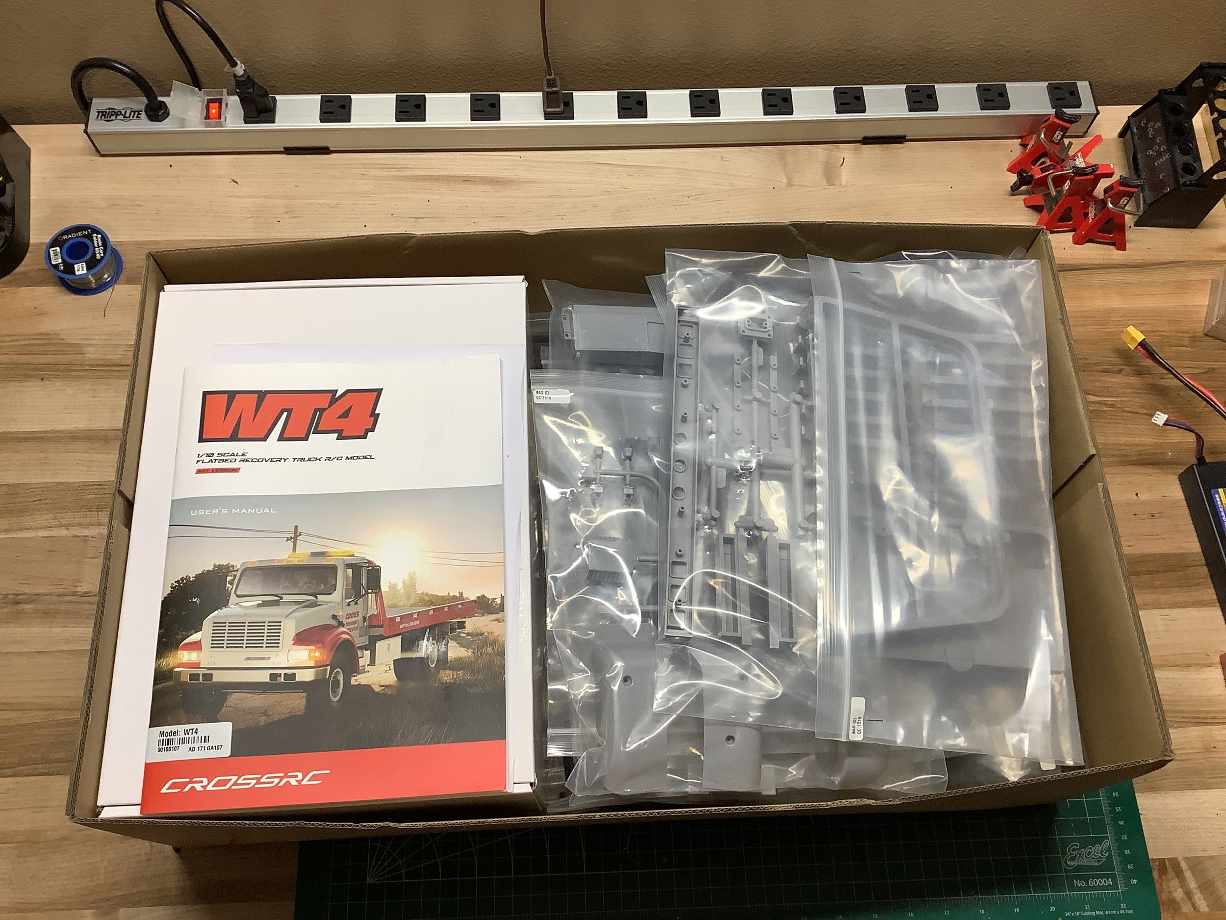
The WT-4 is a truly massive model and it is hard to convey the scale. These pictures of the box don't help much because there is nothing to compare it to. That power strip in the background has 10 sockets and is more than 3 feet long. Inside the box it looks like a plastic models with piles and piles of parts trees as shown on the right.
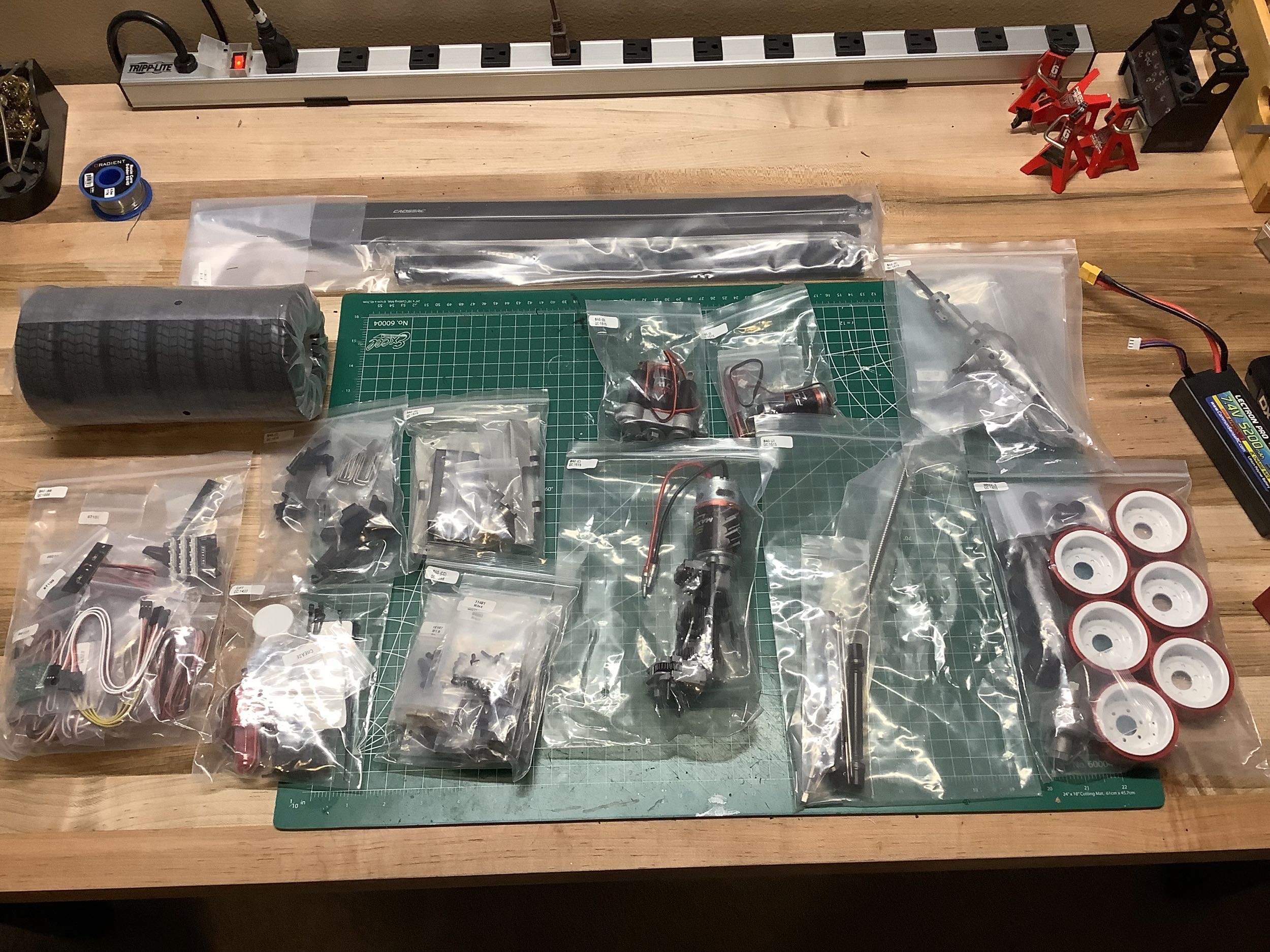
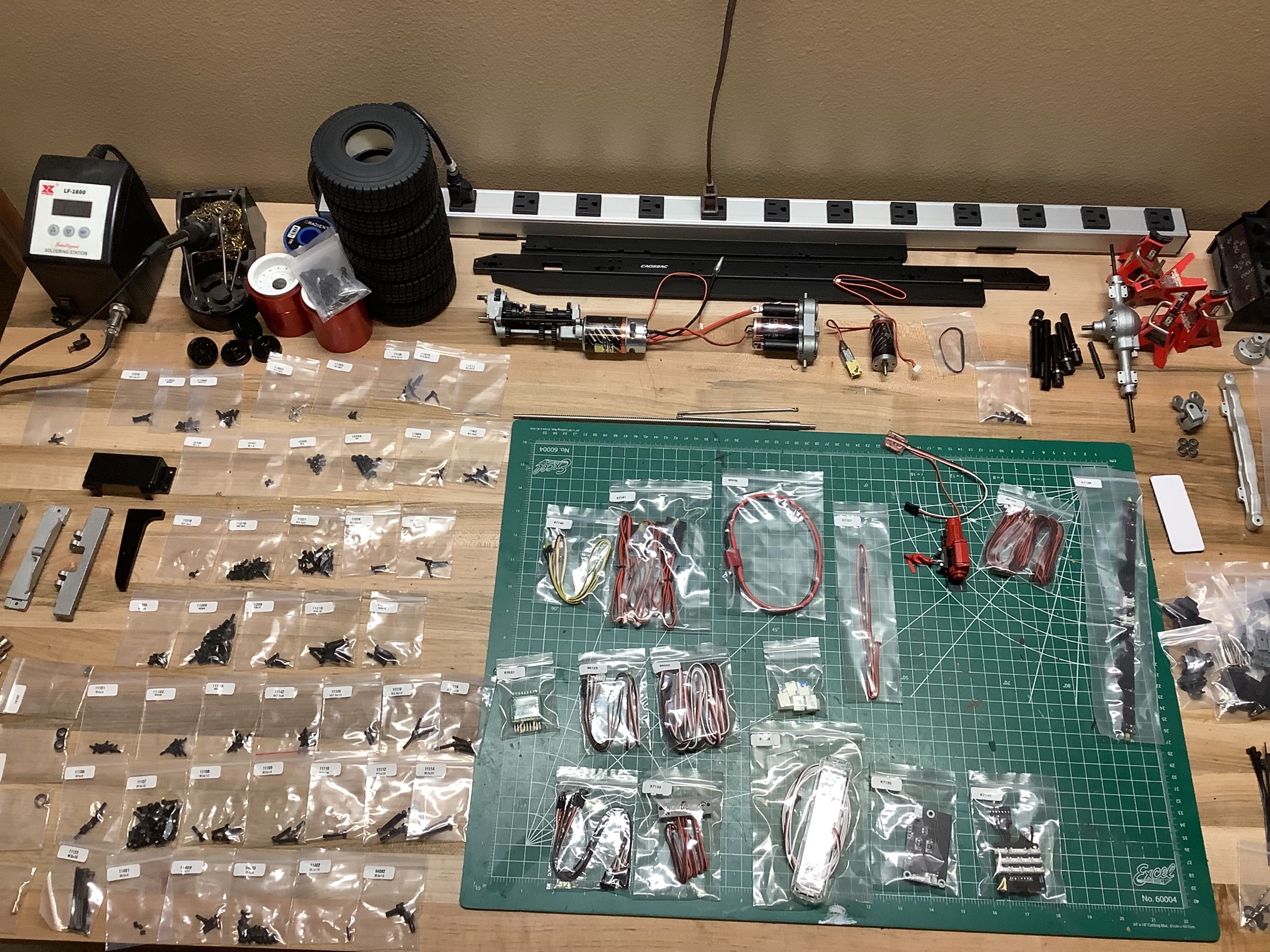
There was no way to lay out all the parts on my table at the same time so I did it in stages. In the photo on the left I've shown the electronics, chassis rails, wheels and tires, and the rear axle. On the right I've laid those parts aside and added all the individually bagged hardware and metal parts. The plastic parts are on the ground next to my desk and not shown at all.
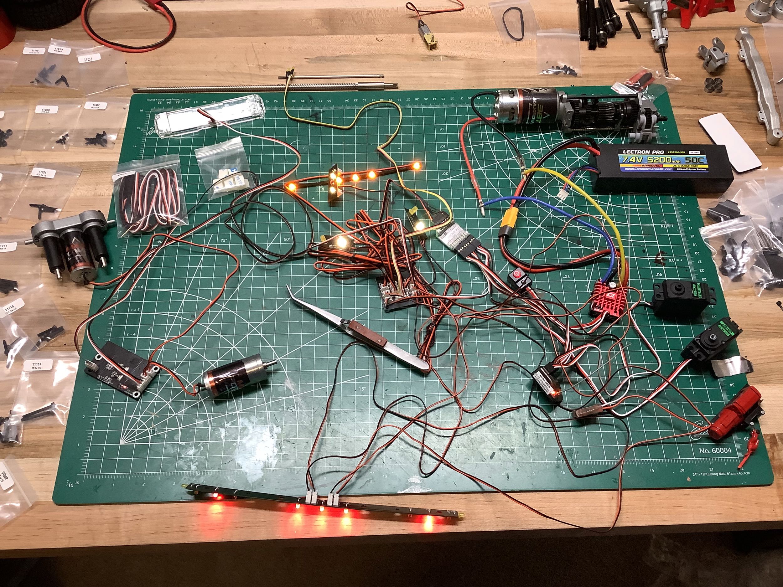
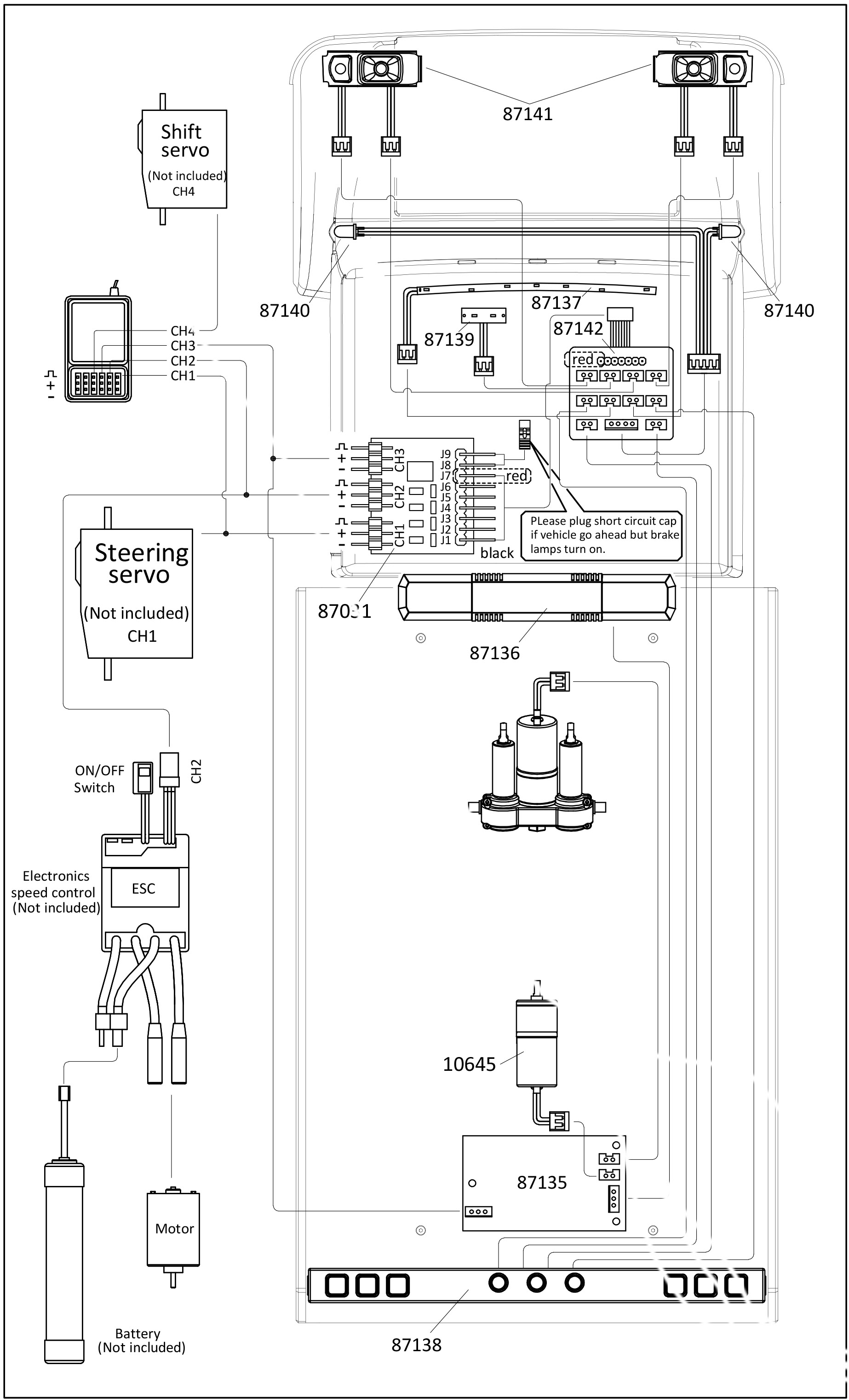
There are a lot of electronics and it's pretty intimidating. The wiring diagram on the right shows the minimum configuration of 4 channels which is already very complicated. Note that it is actually wrong because it shows both the lights and the tip motor connected to the same channel. In the photo on the left I've connected and tested the components for 5 channels, but you would really need 8 to do everything. I've connected steering, throttle, transmission, winch, and tip control. Not currently connected are the headlight control, sound system (which is optional) and the engine belt motor. I only had a 6 channel radio, so in the end I wired it like this:
- Channel 1 - Steering: This is connected to the steering servo and has to be split in parallel to the light controller for the turn signals.
- Channel 2 - Throttle: This is connected to the ESC which
powers the motor and has to be split in parallel to the light
controller for the brake and reverse lights. Note that the on
board BEC powers all the accessories and seems to be adequate.
- Channel 3 - Transmission: This is connected to the shift servo and a two position switch to change between high and low gears.
- Channel 4 - Sound: This is connected to the sound controller and a three position switch to start/stop the engine sound and honk the horn.
- Channel 5 - Tip: This is connected to the bed tip control board and a three position switch. Even though there are two motorized functions (tip and extend), they both run off the same channel which I'll explain more in detail later. Note that these motors use the control board as an ESC and just run off of 6V receiver power.
- Channel 6 - Winch: This is connected to the winch and a three position switch for extending or retracting.
- I connected the lights to a servo controller in the cab which just leaves them on all the time by default unless you open the door and turn the dial manually.
- I hooked up the engine belts with a toggle switch located under the hood. There is really no reason to need to control this remotely.
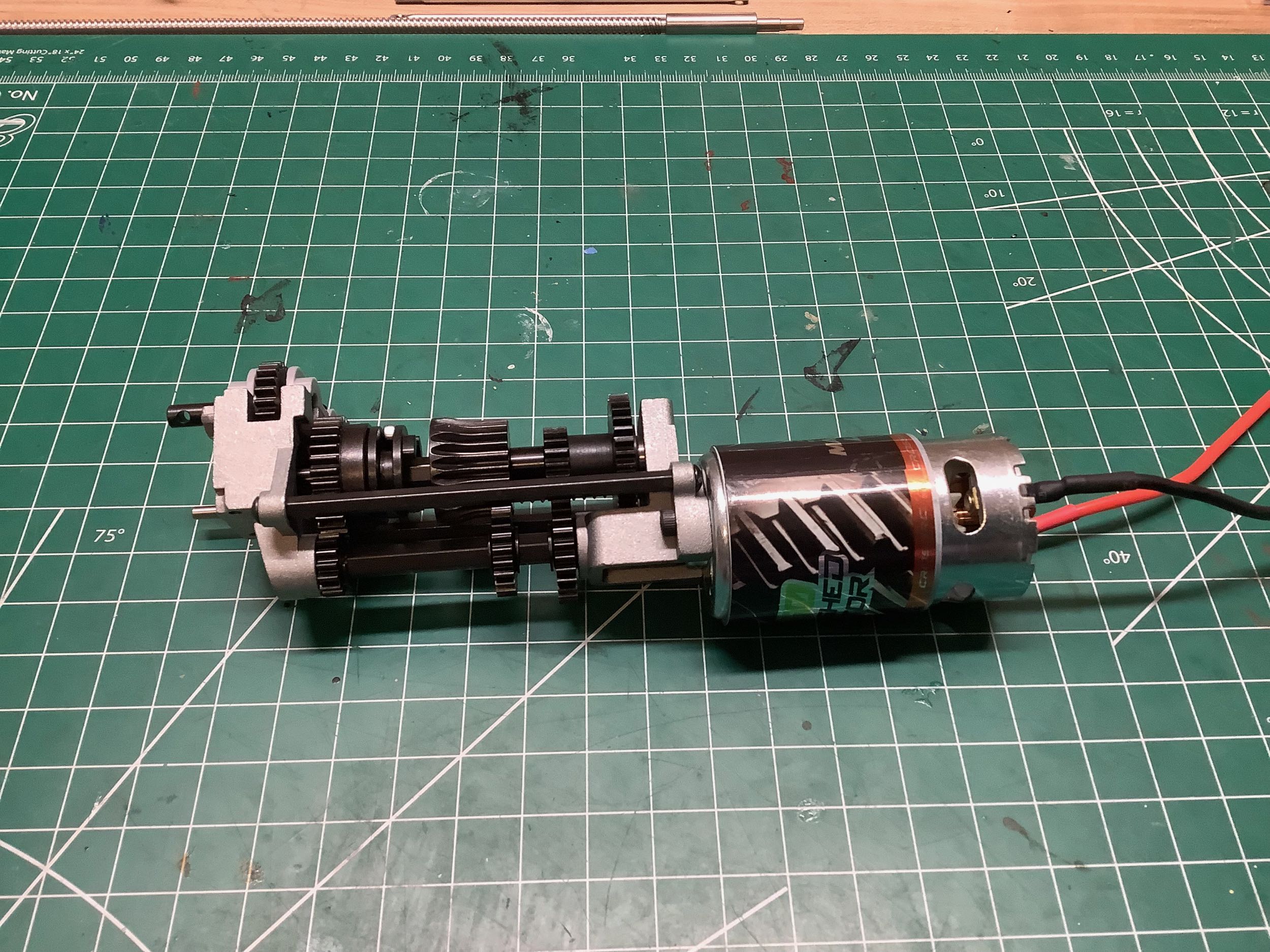
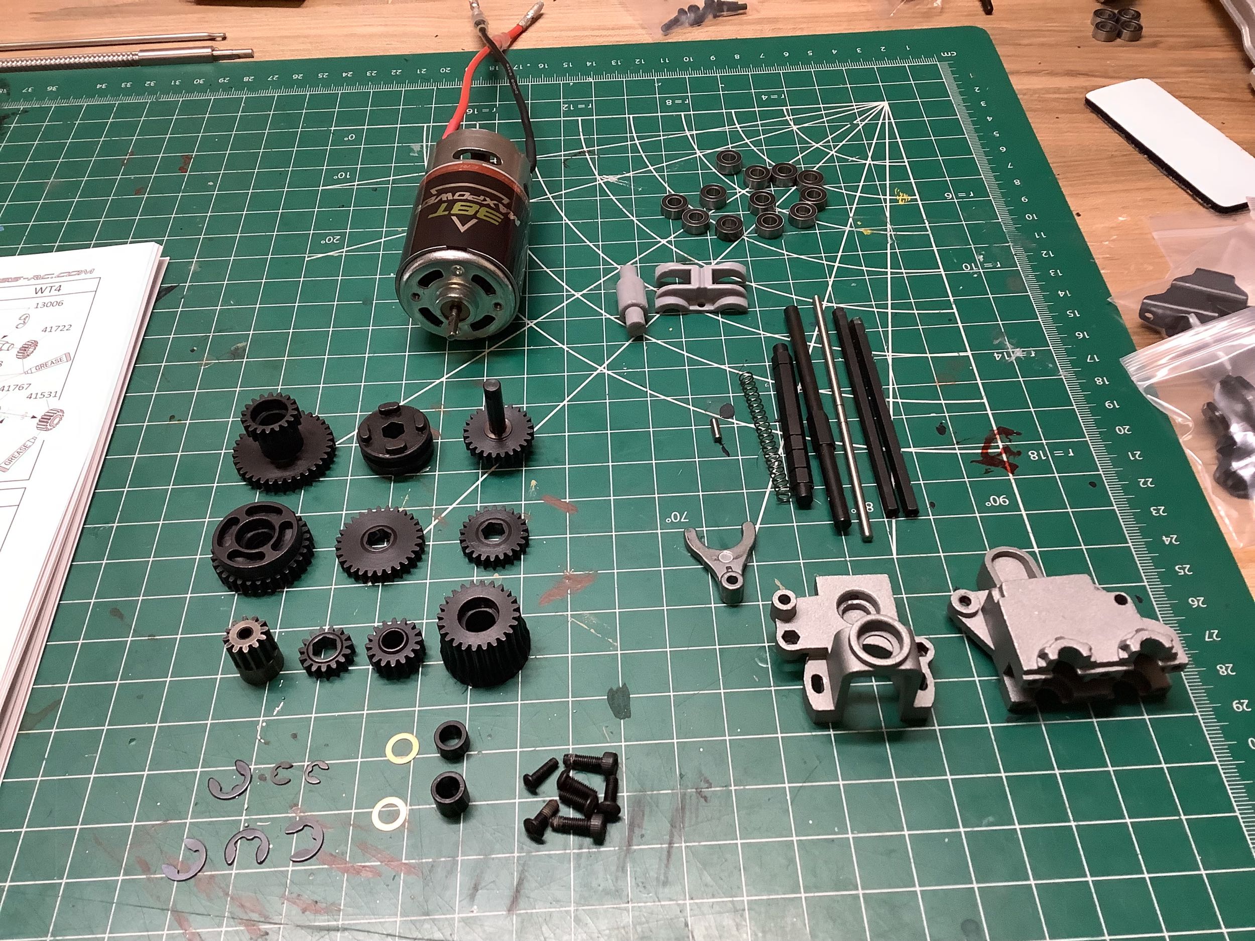
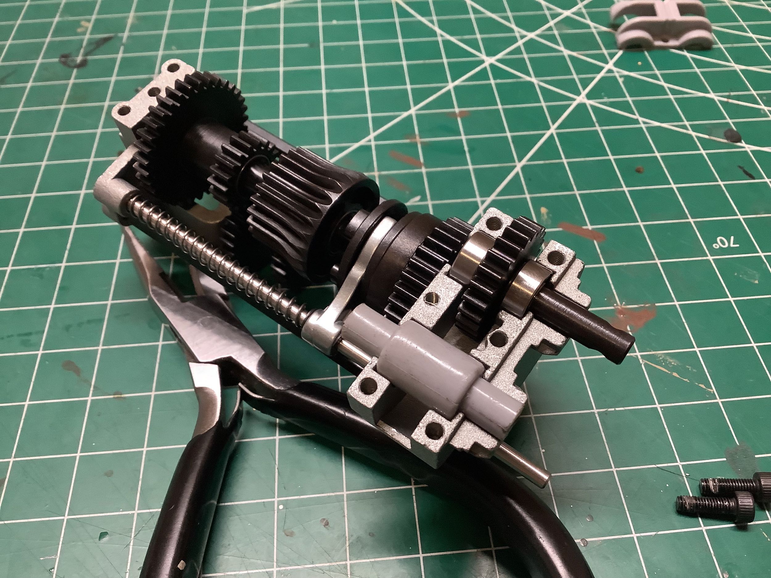
Sometimes kits come with sub-assemblies already completed which is, of course, unacceptable. The photo on the left shows the motor and transmission assembly as it came out of the box. Luckily the manual includes instructions for the transmission so I went ahead and tore it all down as shown on the right. These are some seriously strong steel gears and there are ball bearings throughout.
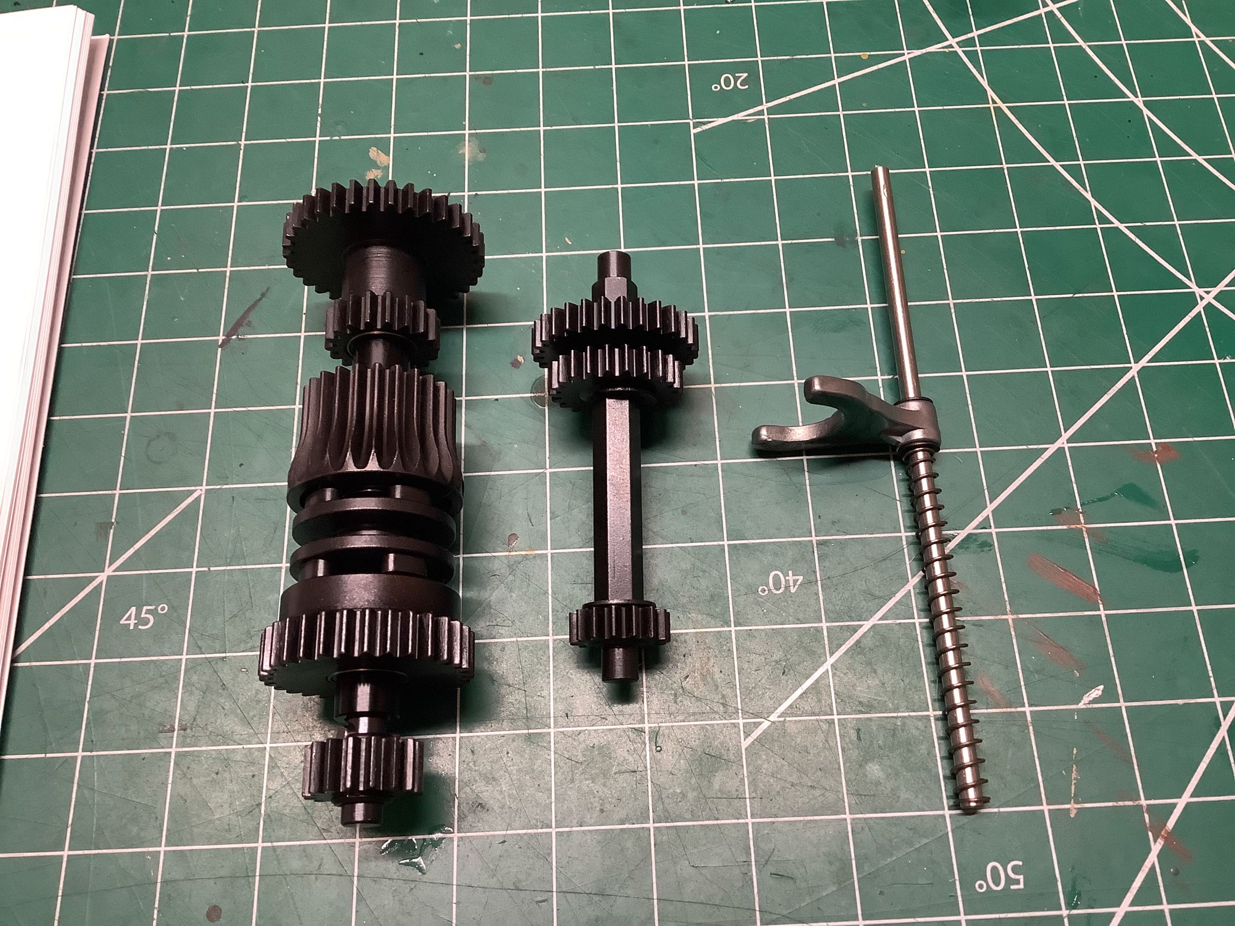
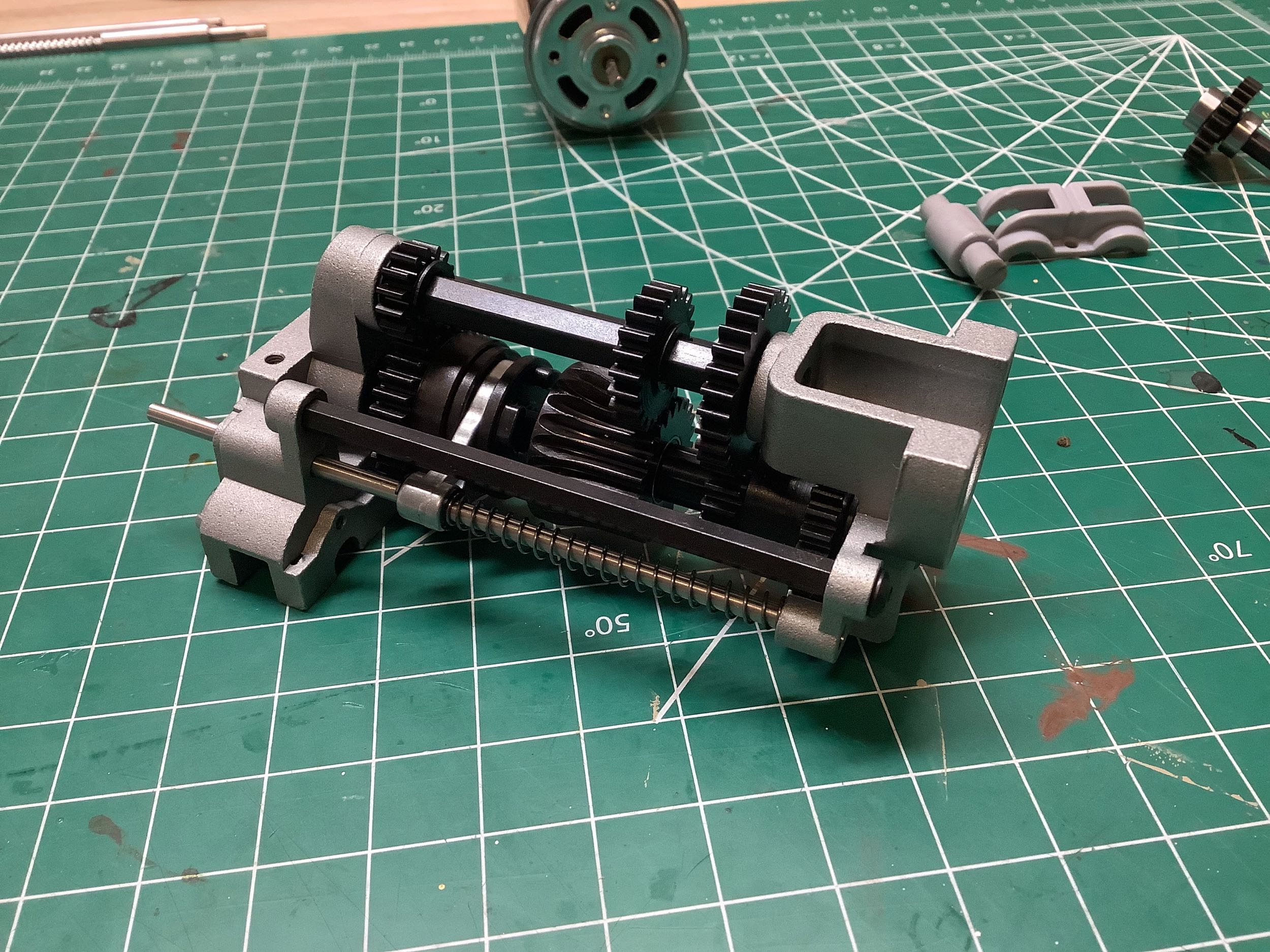
Here I've assembled the main shaft and the lay shaft. In the main shaft on the left, most of the gears can spin freely on the shaft. Only the drive ring is locked to the shaft with a hex. The lay shaft in the middle is hex along its entire length and all three gears are locked to it. The final rod on the right contains the shift fork. The photo on the right shows how the gears mesh and how the shift fork engages with the shift ring when the shafts are installed between the housing ends.
Now I've flipped over the transmission and you can see the output shaft on the right which will connect to the drive shaft. That grey plug would be used to go to a front drive shaft if you had a four wheel drive truck. I derived the gear ratios as follows:
- 1st stage - Motor pinion = 12:34 = 2.83:1
- 2nd stage - Lay shaft = 18:28 = 1.56:1
- 3rd stage - Main shaft = 15:31 = 2.07:1 (low gear) or 22:24 = 1.09:1 (high gear)
- 4th stage - Transfer case = 16:24 = 1.50:1
- 5th stage - Differential = 18:34 = 1.89:1
- Final Drive = 25.81:1 (low gear) or 13.62:1 (high gear)
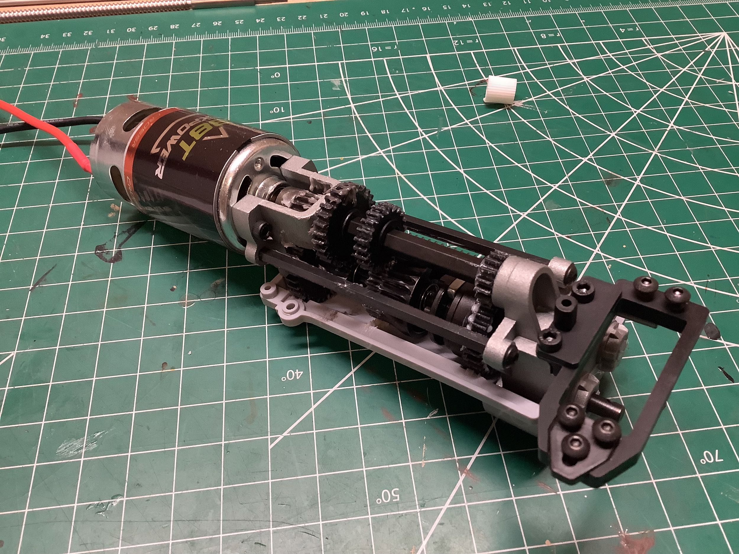
As you can see, there is about a 2x difference between high and low
gear. On the right I've added the 560 sized 38T brushed motor and a
mount for the mini shift servo. I never took a photo of the shift
servo installed, but it is a proprietary size so I got it directly from
Cross RC.
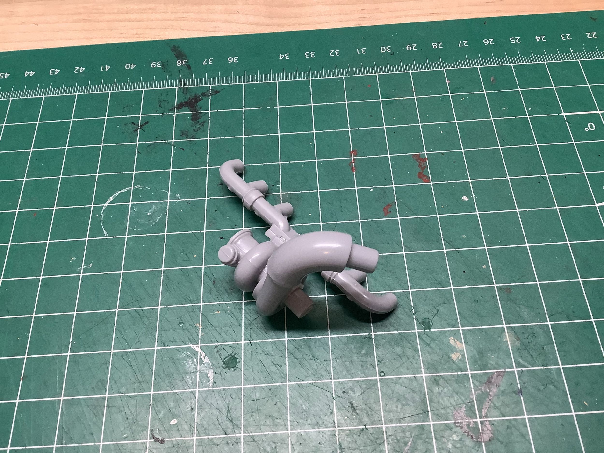
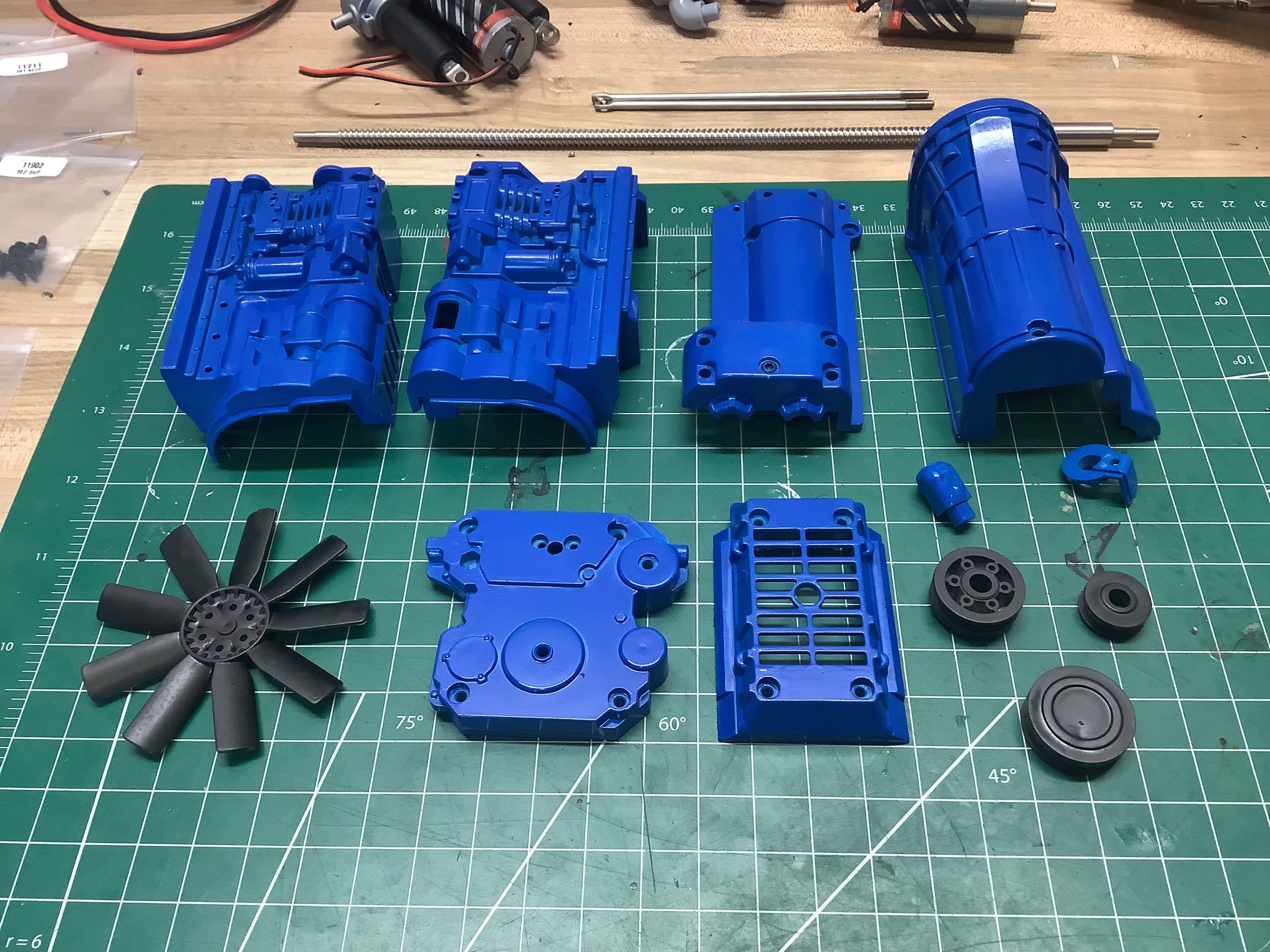
This model doesn't just install a boring transmission; it is full of scale details. On the left in the straight-6 exhaust manifold and turbo. On the right I've painted all the engine and transmission housing bits blue, and I've painted the fan and pulleys black. Why blue? I wanted some contrast when the hood was opened, and these big trucks often have painted blocks.
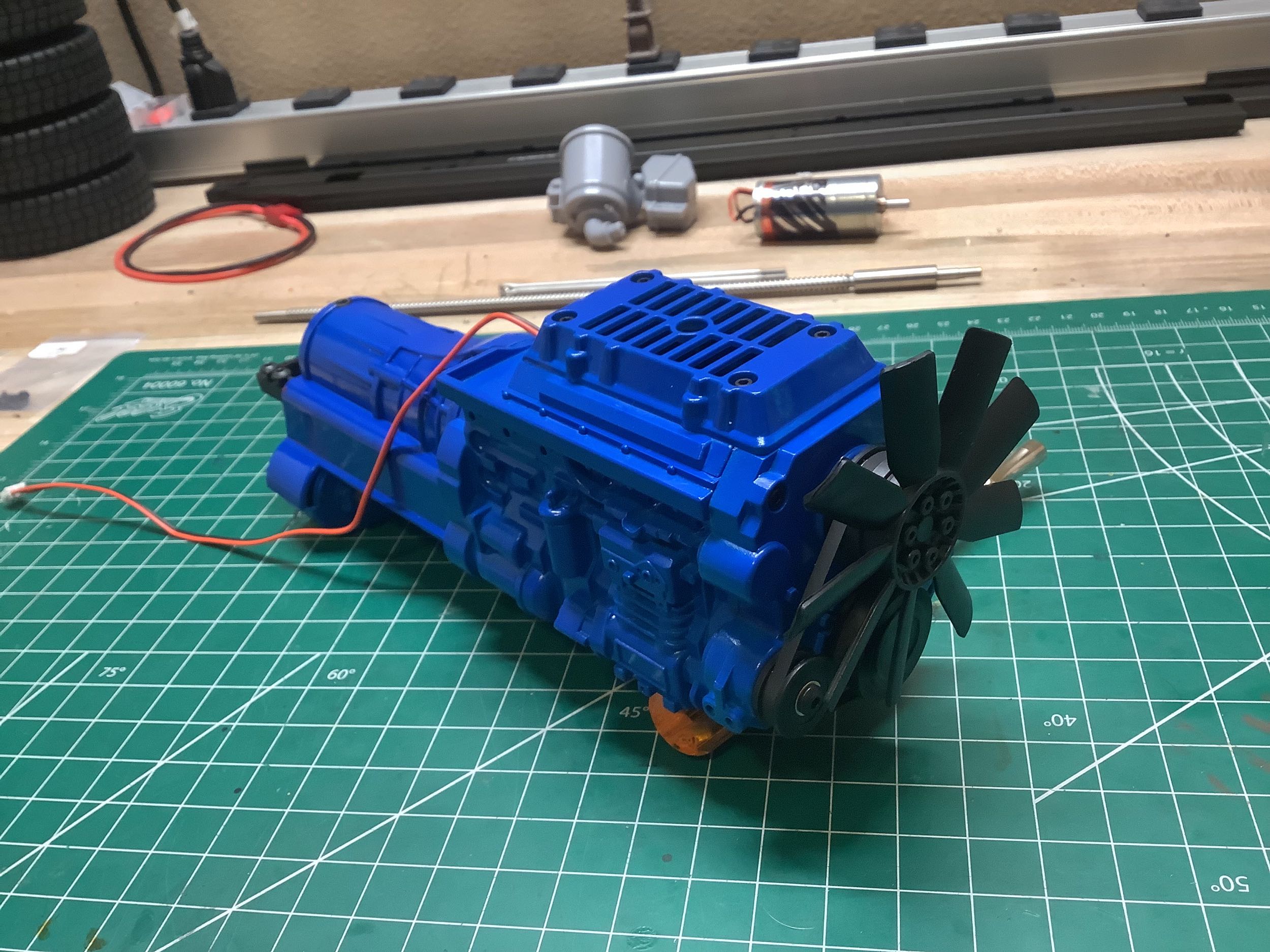
On the left I've installed the mechanical assembly into the housing. It really looks like a genuine engine and you can't tell that all those mechanical and electrical components are inside. The open grill on the top is to provide some air flow to cool the motor and has space for an optional electric fan. That little wire you see coming out the back is for the belt motor which is shown in more detail on the right. This little motor drives one of the pulleys and spins the fan via a belt. Don't worry, I greased all the gears before closing everything up.
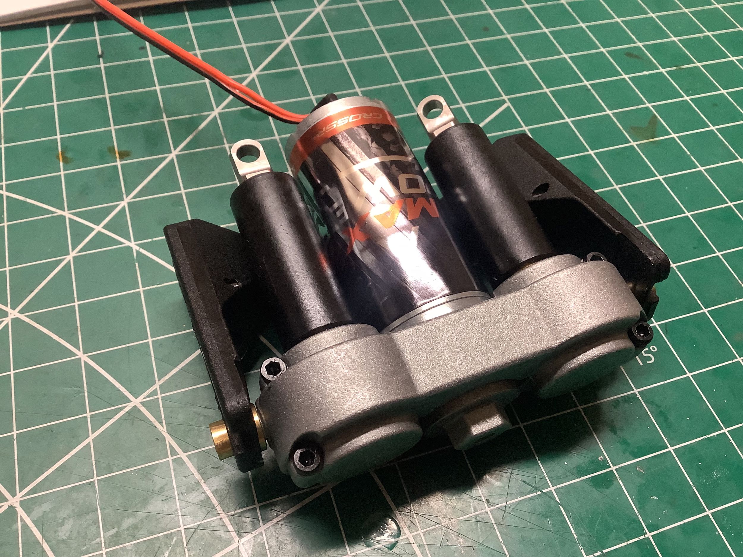
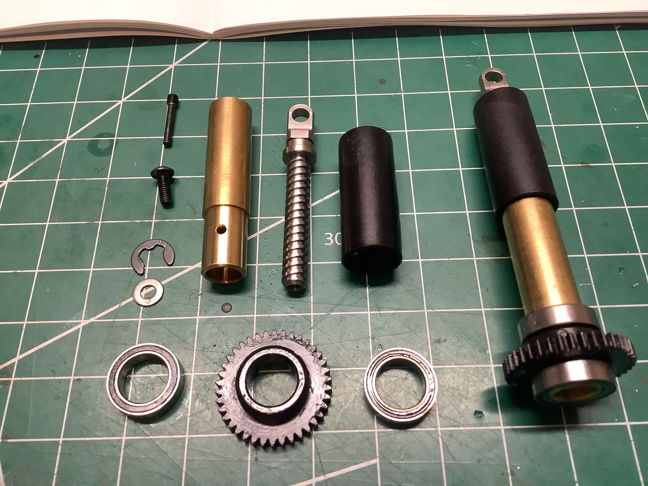
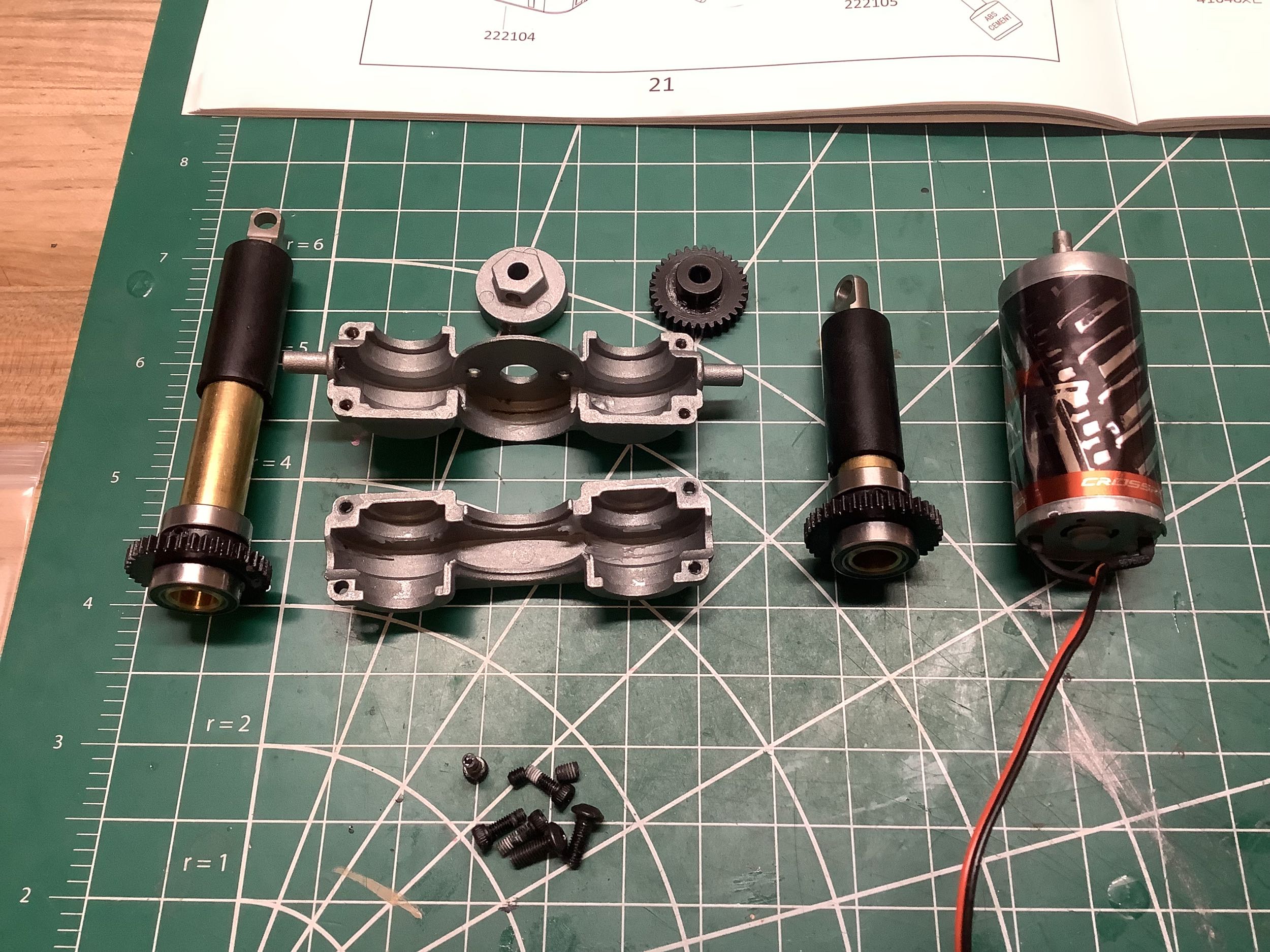
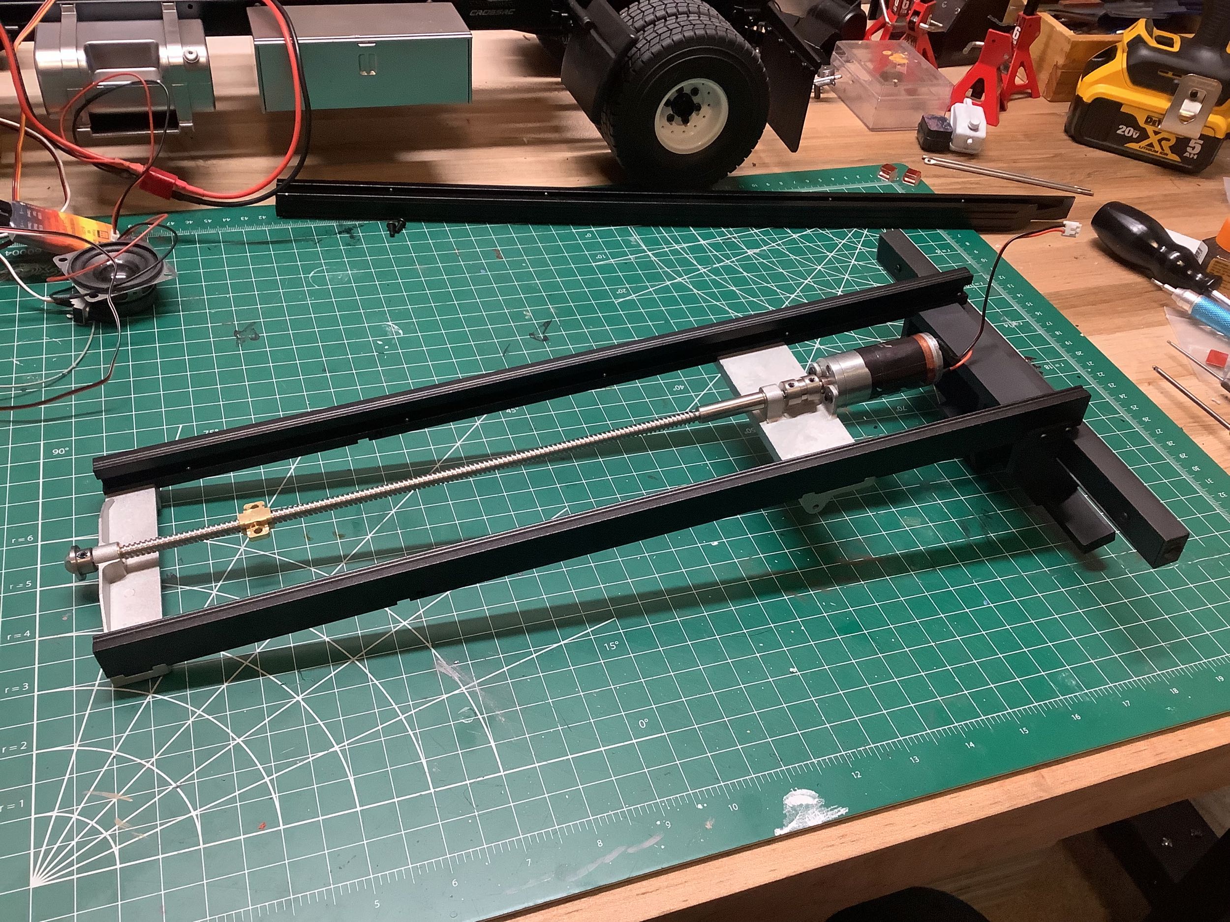
Here's another mechanism which was assembled out of the box but I rebuilt. The motor in the middle is powered by the BEC and drives the two linear actuators which tilt the bed. There is a substantial gear reduction (5 stages) inside the motor housing itself which I know for reasons I will explain later. The actuators consist of a spinning brass outer cylinder which is internally threaded to drive a fixed rod with an acme screw. The drive gears pin to the brass cylinders. The black plastic sleeve is just there to keep debris out of the threads but has no mechanical function.
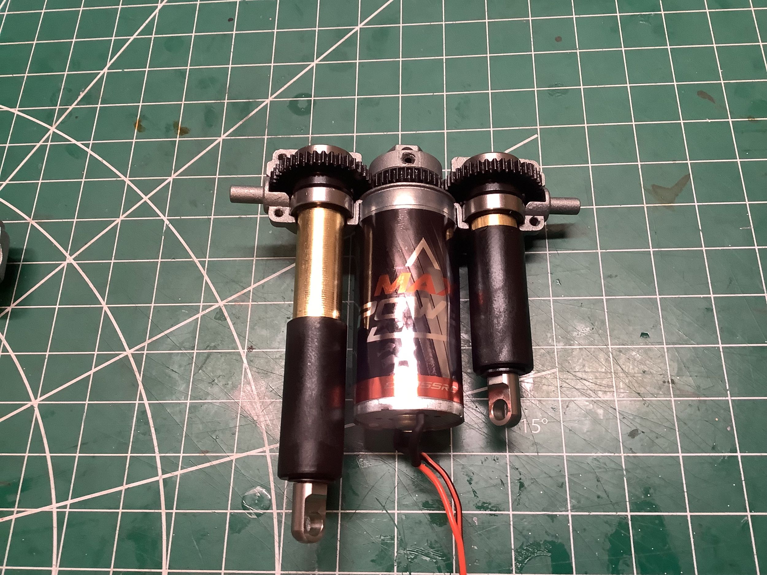
Here are the actuators, the motor, and the housings. The lower gear housing has trunnions on the sides which fit into brackets that mount to the chassis rails. This allows the whole assembly to pivot as the bed tilts. On the right I've placed everything into the housing. You can see at this point that one actuator is extended and one is retracted. It is important to match their lengths before installing the whole assembly into the truck.
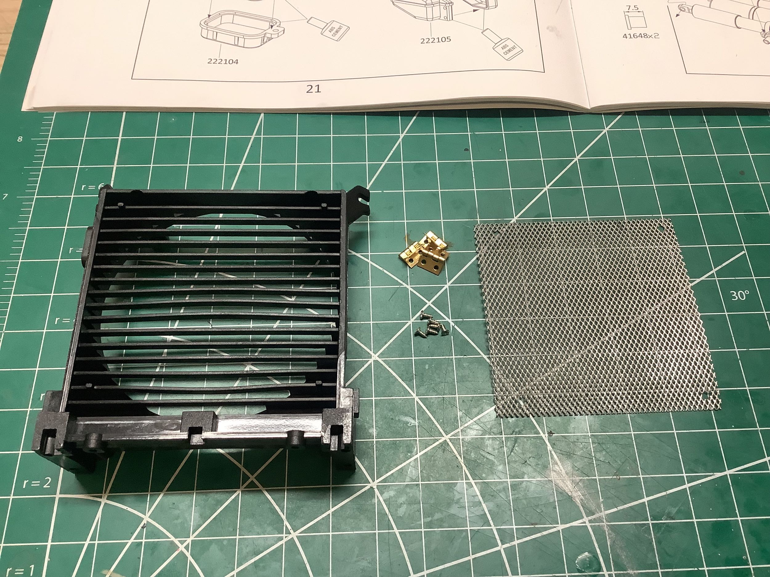
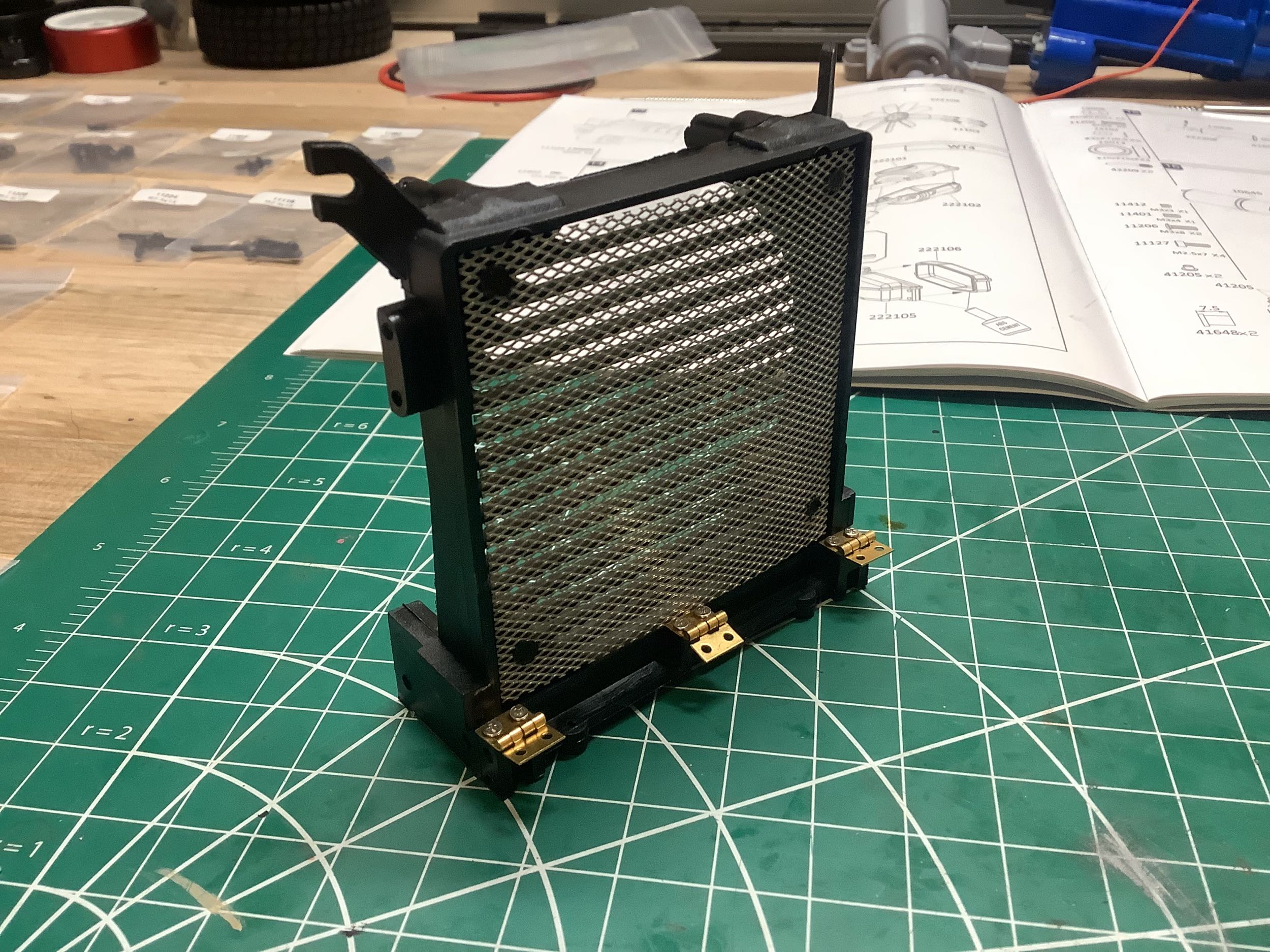
Let's make a few more scale details. Here we have a faux radiator and a nice mesh grill. This actually becomes the support for the whole hood. Those hinges attach to the front chassis cross member and then the whole thing pivots with the hood. These are pretty tiny hinges for such a purpose, but the hood is light. It would be fiberglass on the real truck.
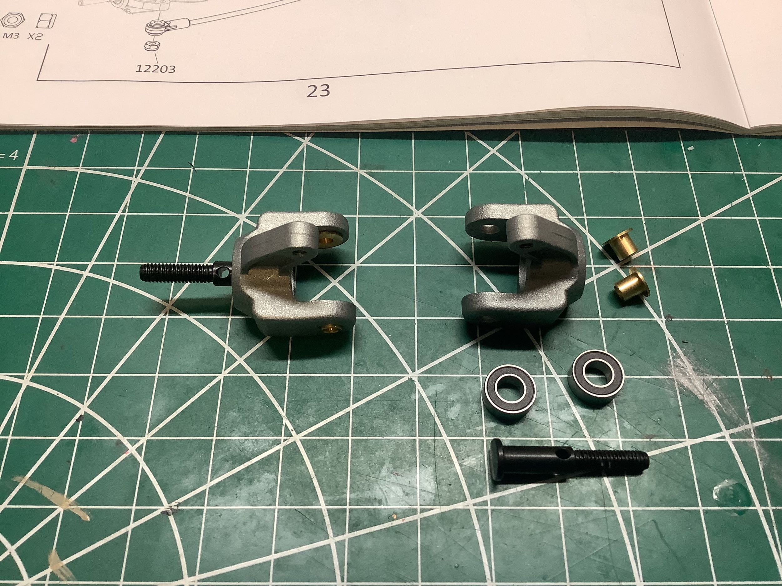
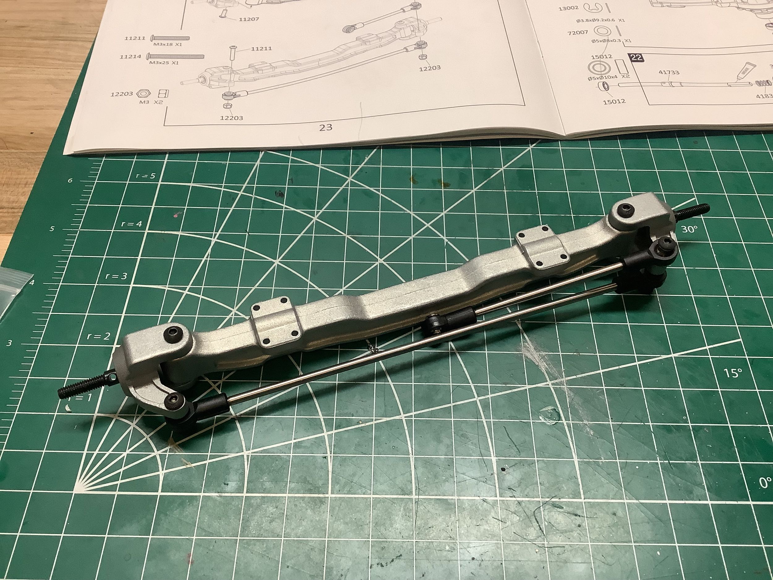
Now I'll build the front axle which is not driven and does not have independent suspension so it is just a solid bar with some steering knuckles. There is no fancy suspension geometry like kingpin inclination, caster, or camber, but there is some slight Ackerman correction.
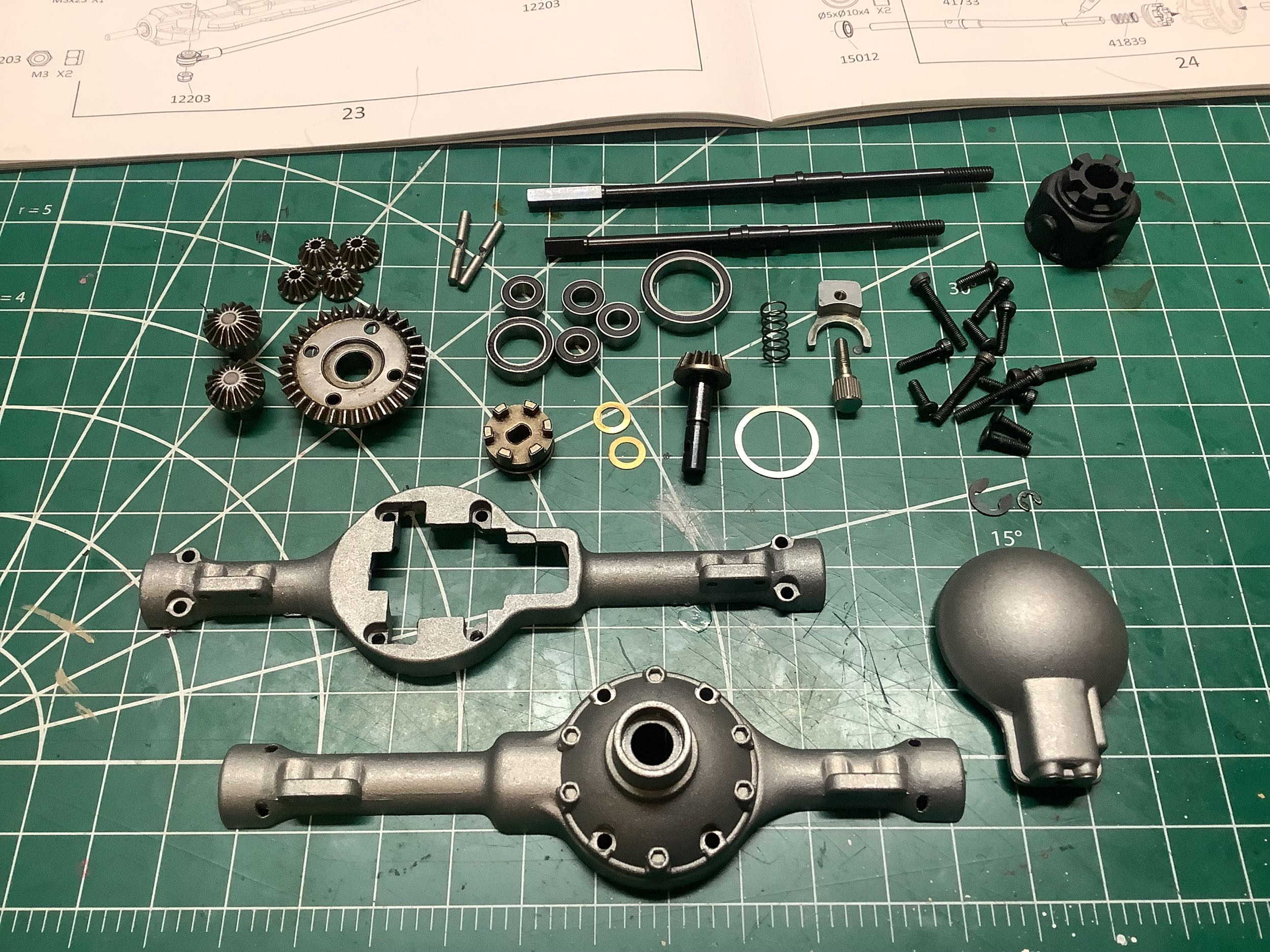
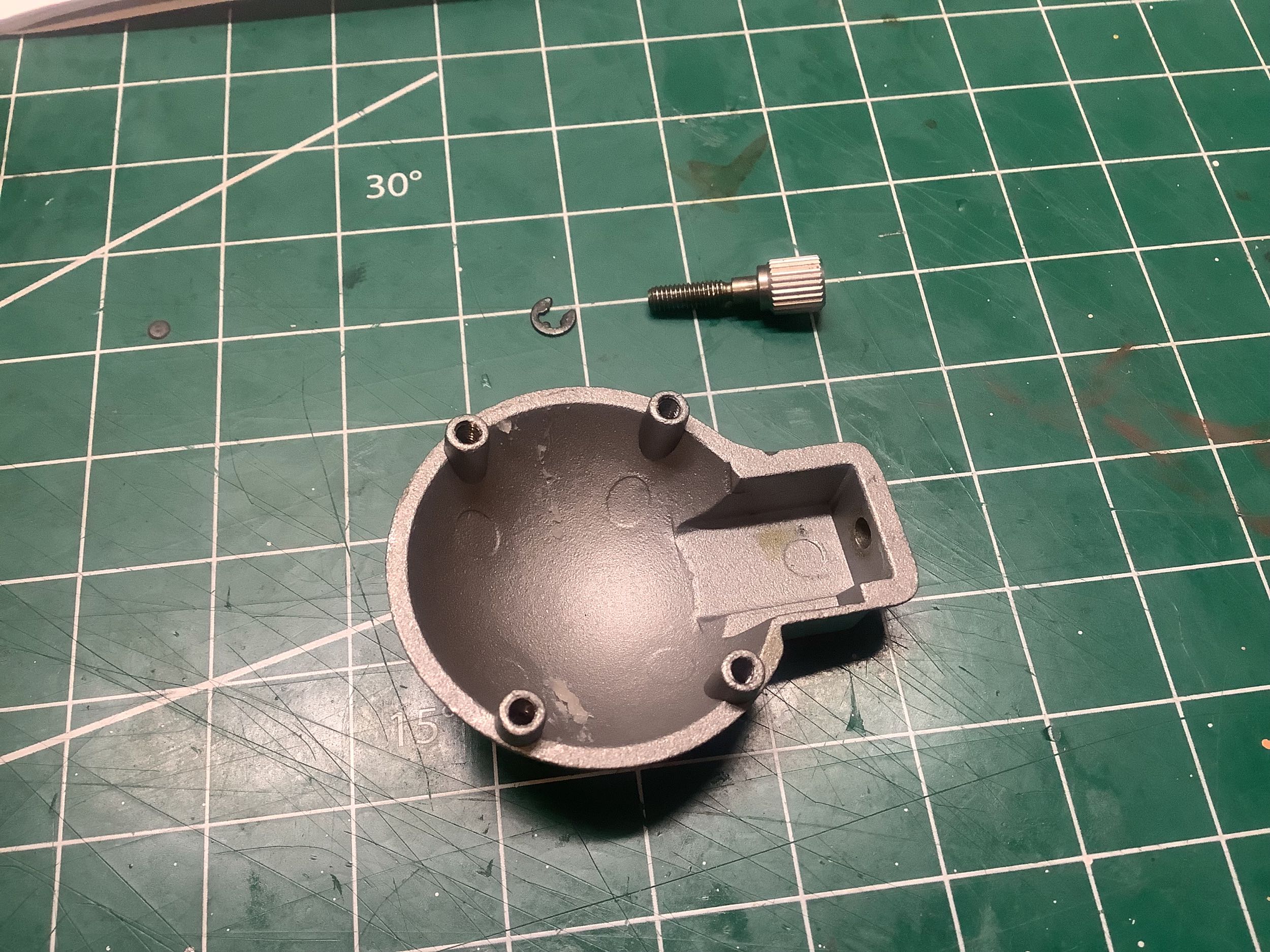
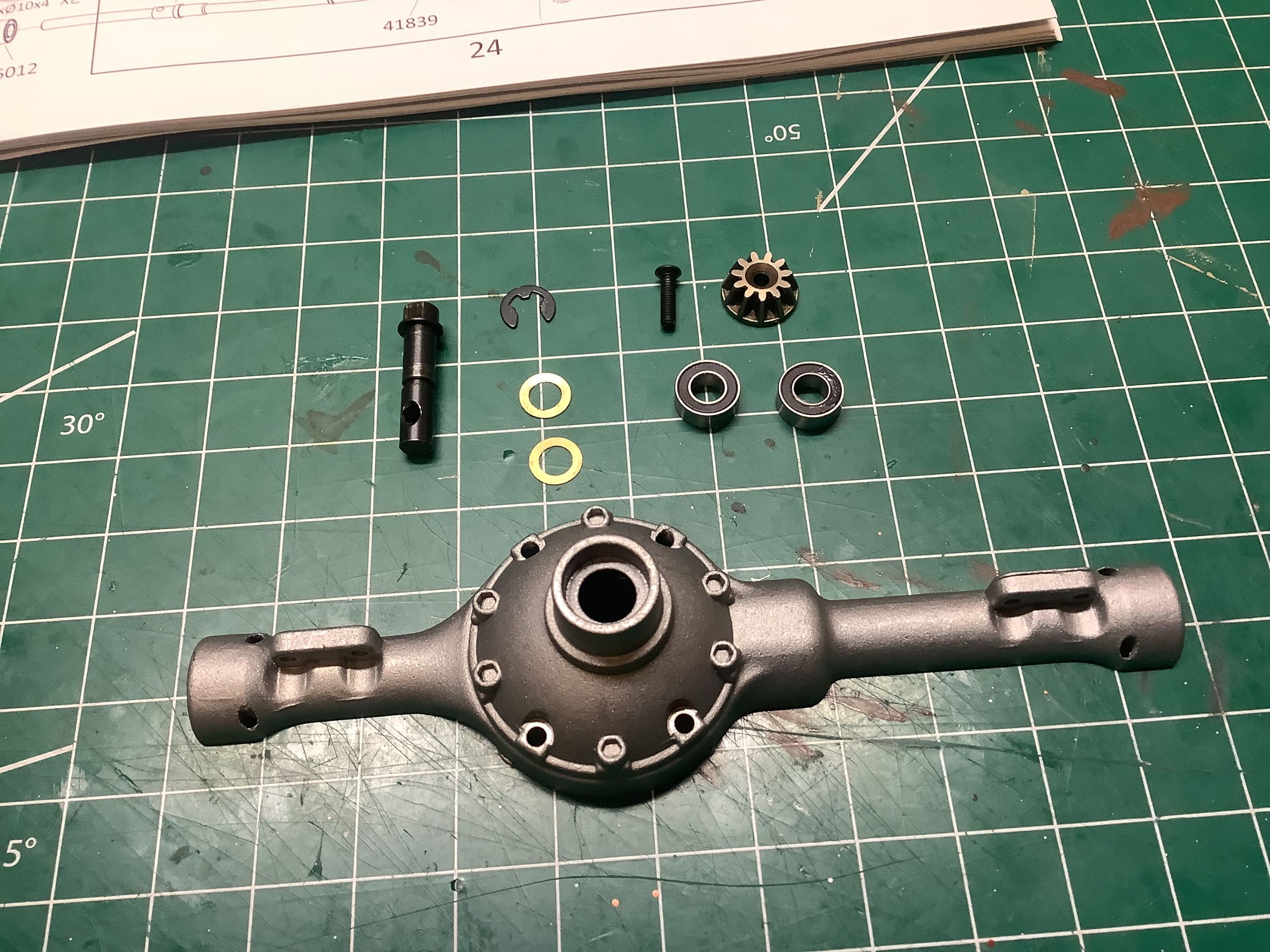
The rear axle also came assembled but I've torn it down as shown. I'm glad I did because apart from needing to be greased, there is actually a lot going on here. It is always important that I know how everything works. Usually the axle housing would be in two pieces, but this one is in three which allows the rear cover to be easily removed to access the gears without taking the whole thing apart. The housings are cast aluminum, but the axles and gears are hardened steel. Take note of that little thumb screw on the right, it's going to be important.
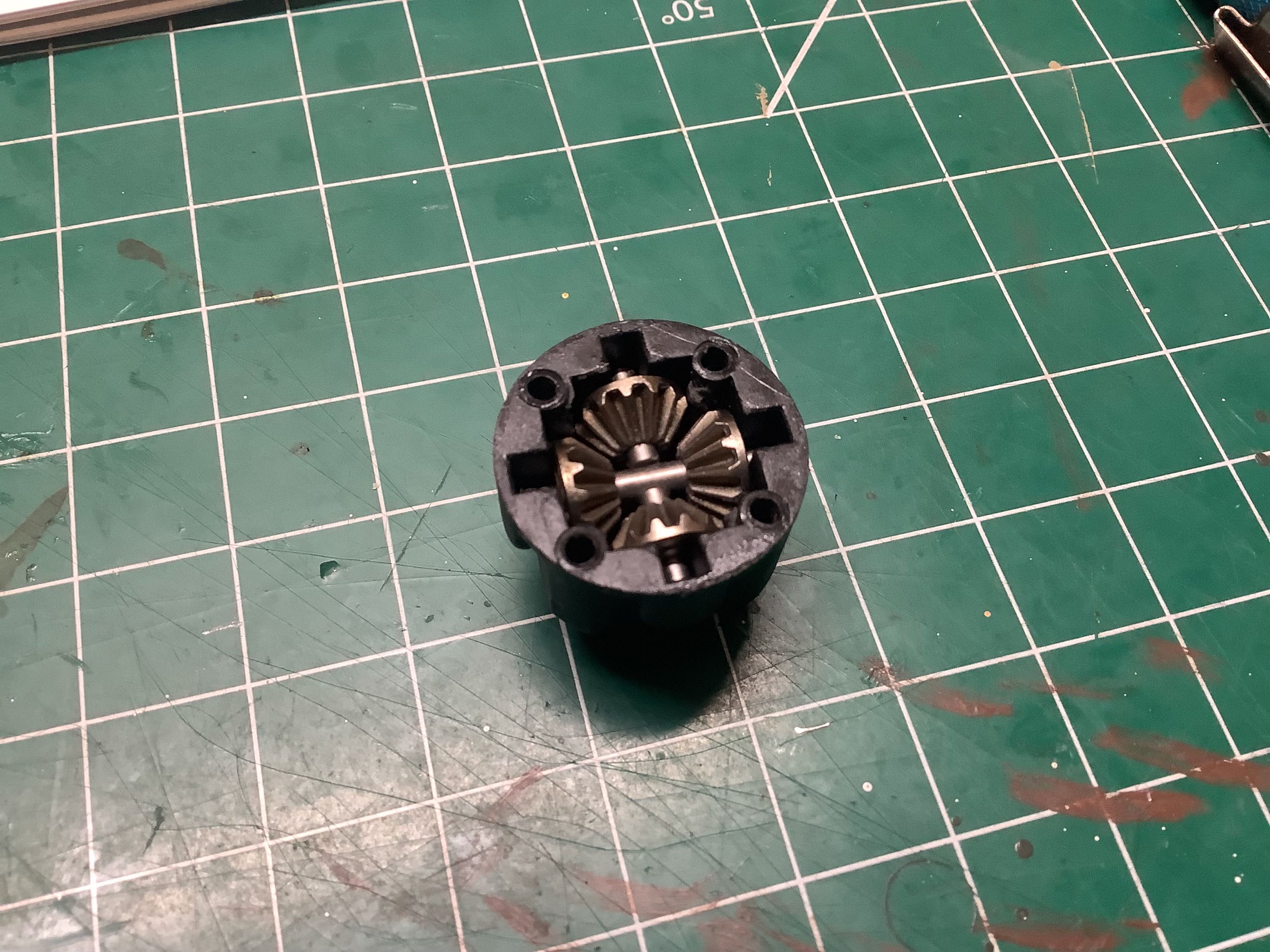
The differential is not sealed so it can't be filled with oil, but it does use four spider gears so it is quite strong. Look at those massive bearings on the right. Inside the bearing you can see some slots which are used for the differential locking function.
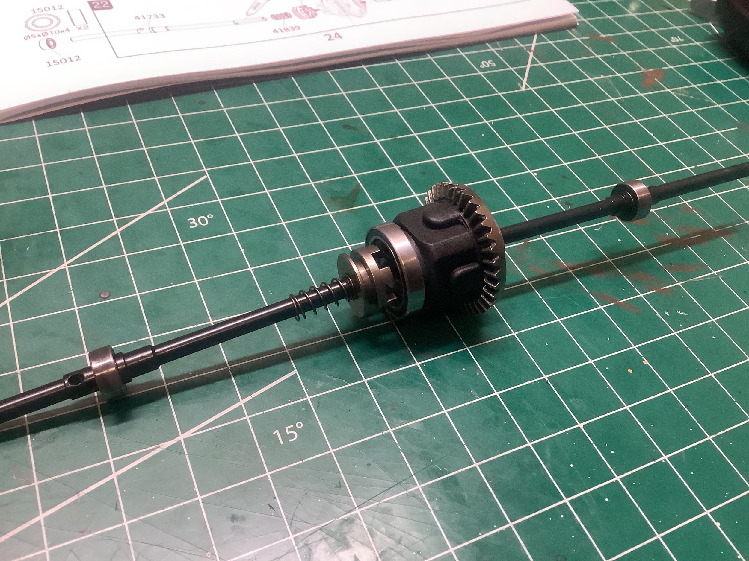
Now I've installed the axle halves into the differential. That drive ring on the left is locked to the left axle. If it is pushed into the diff housing, it will lock the left axle to the housing, effectively locking the whole differential. The thumb screw in the rear cover is used to manually translate the driving ring and lock or unlock the differential.
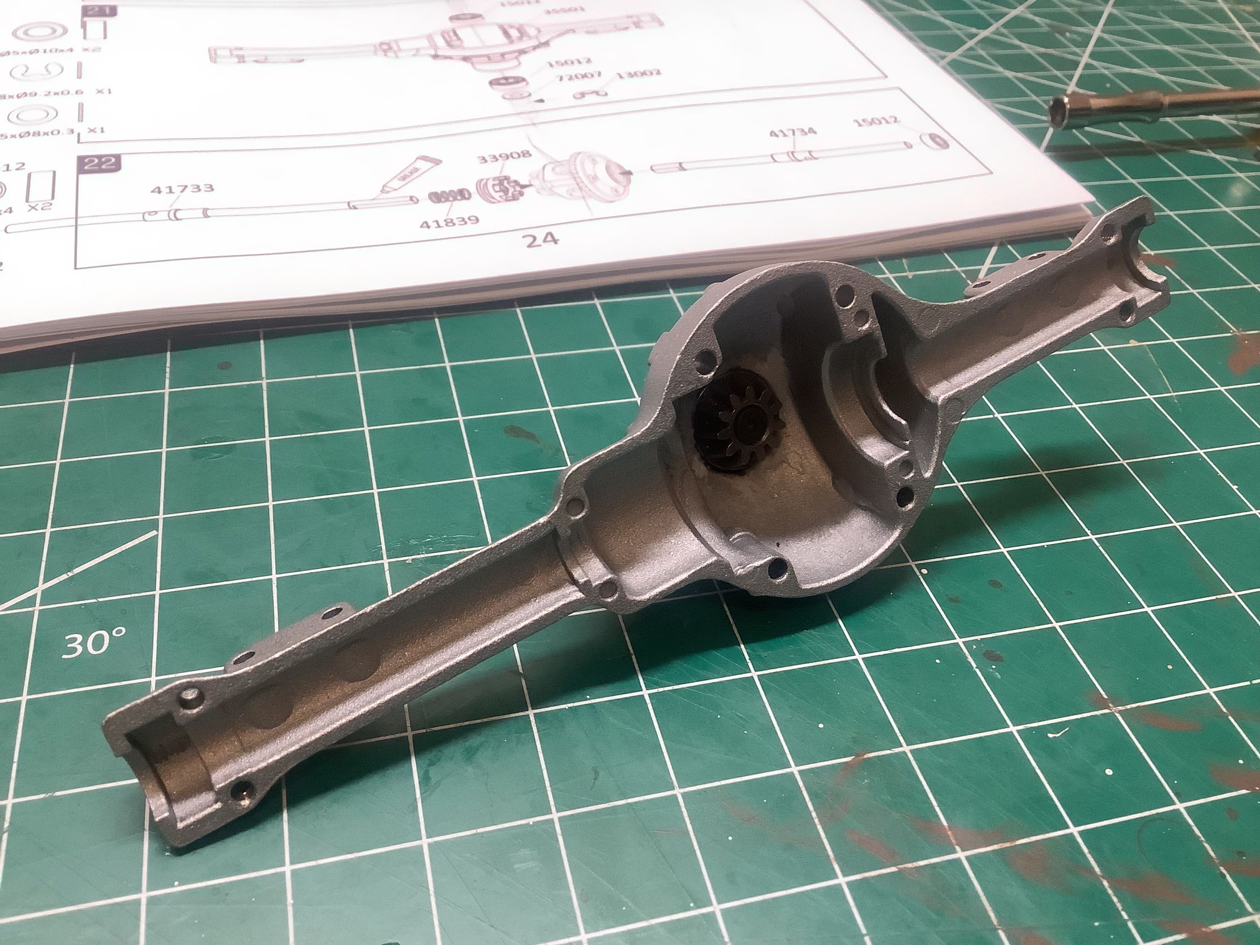
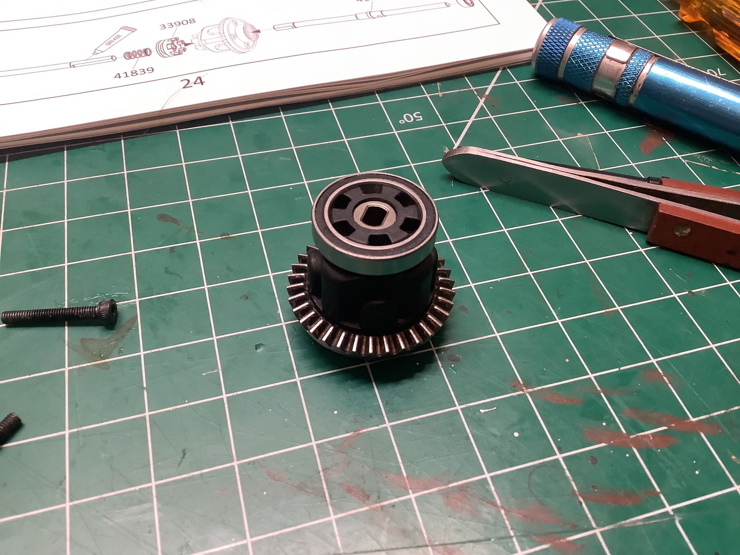
The pinion gear gets installed into the third member on the front housing as shown. This housing also has bearing seats and leaf spring mounts.
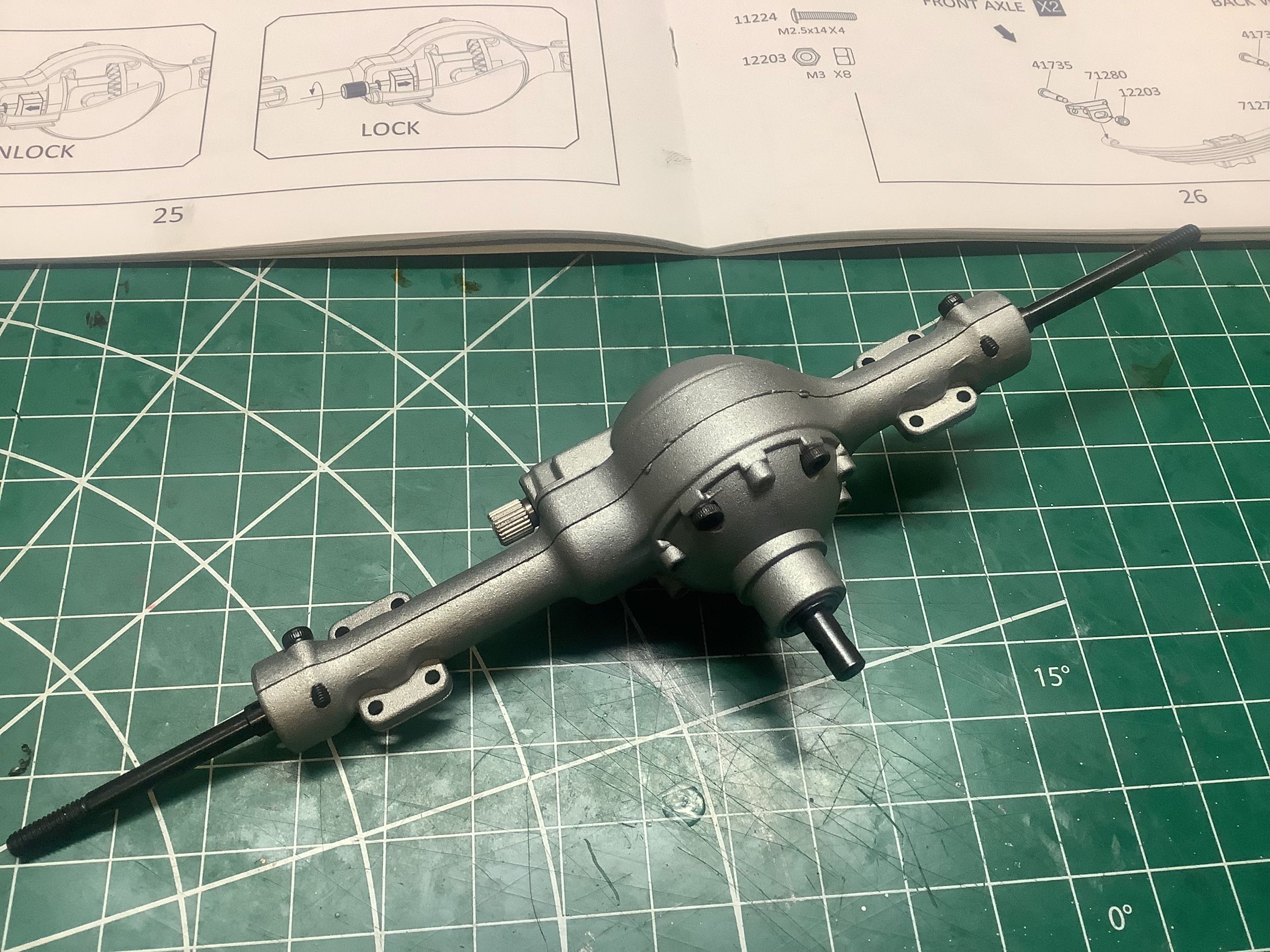
Here is the completed rear axle. Note how far the axle shafts protrude from the housing to support the dual wheels on either side.
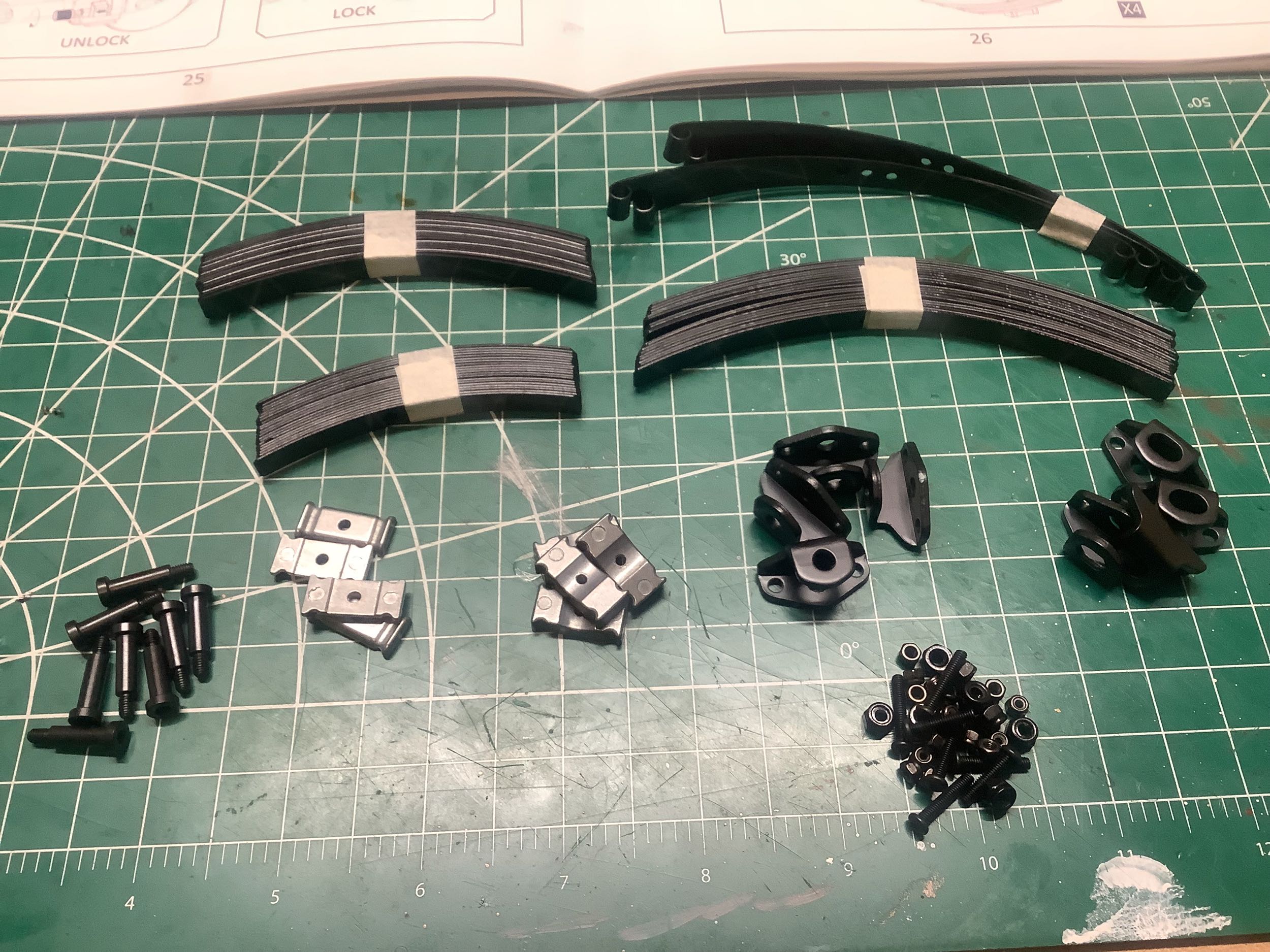
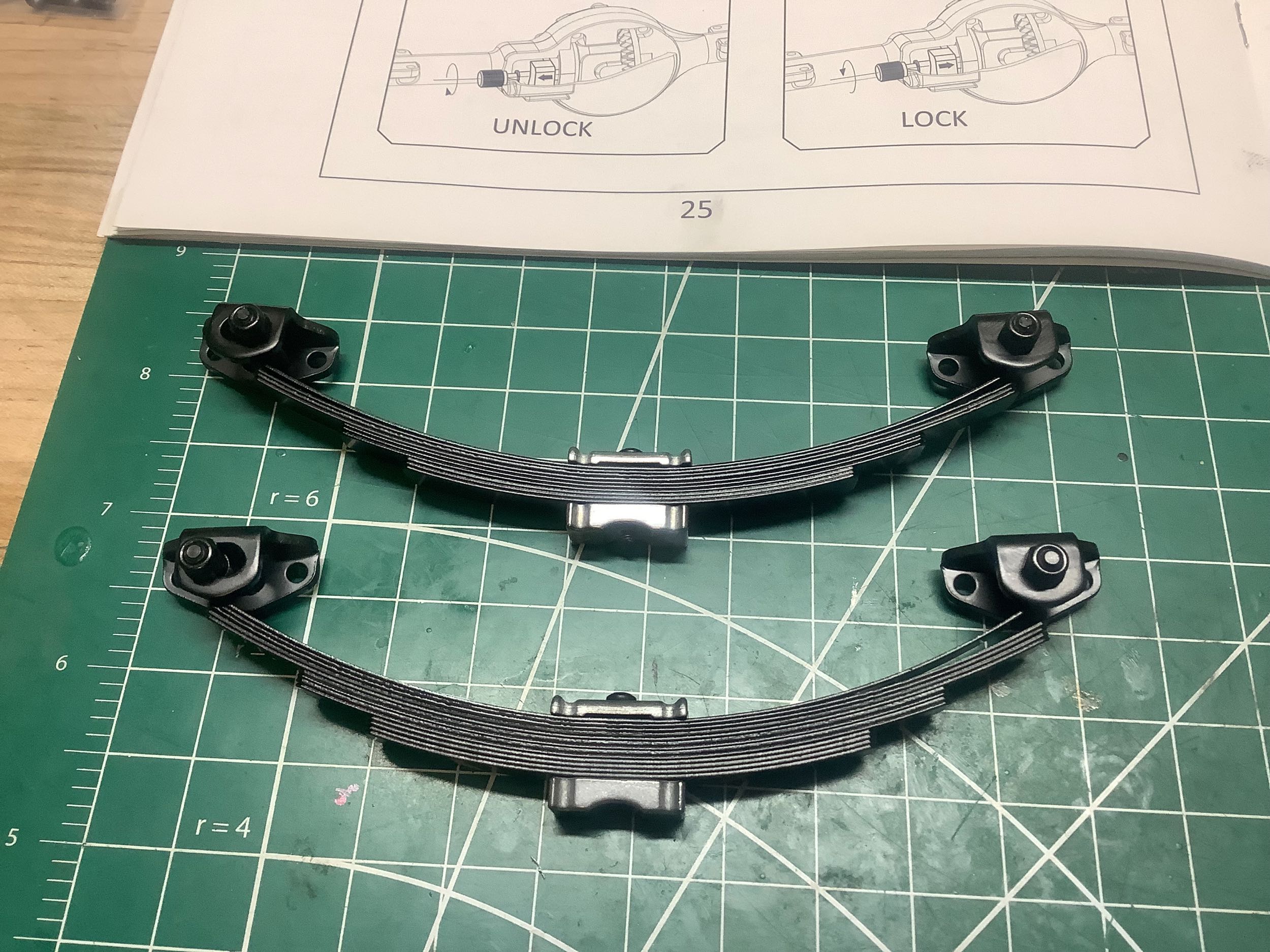
They are not messing around with these leaf springs. The front springs use 10 leaves and the rear springs use 13 leaves each. That means this is going to bounce hard like a real truck (there are also no dampers) but be able to support a lot of weight.
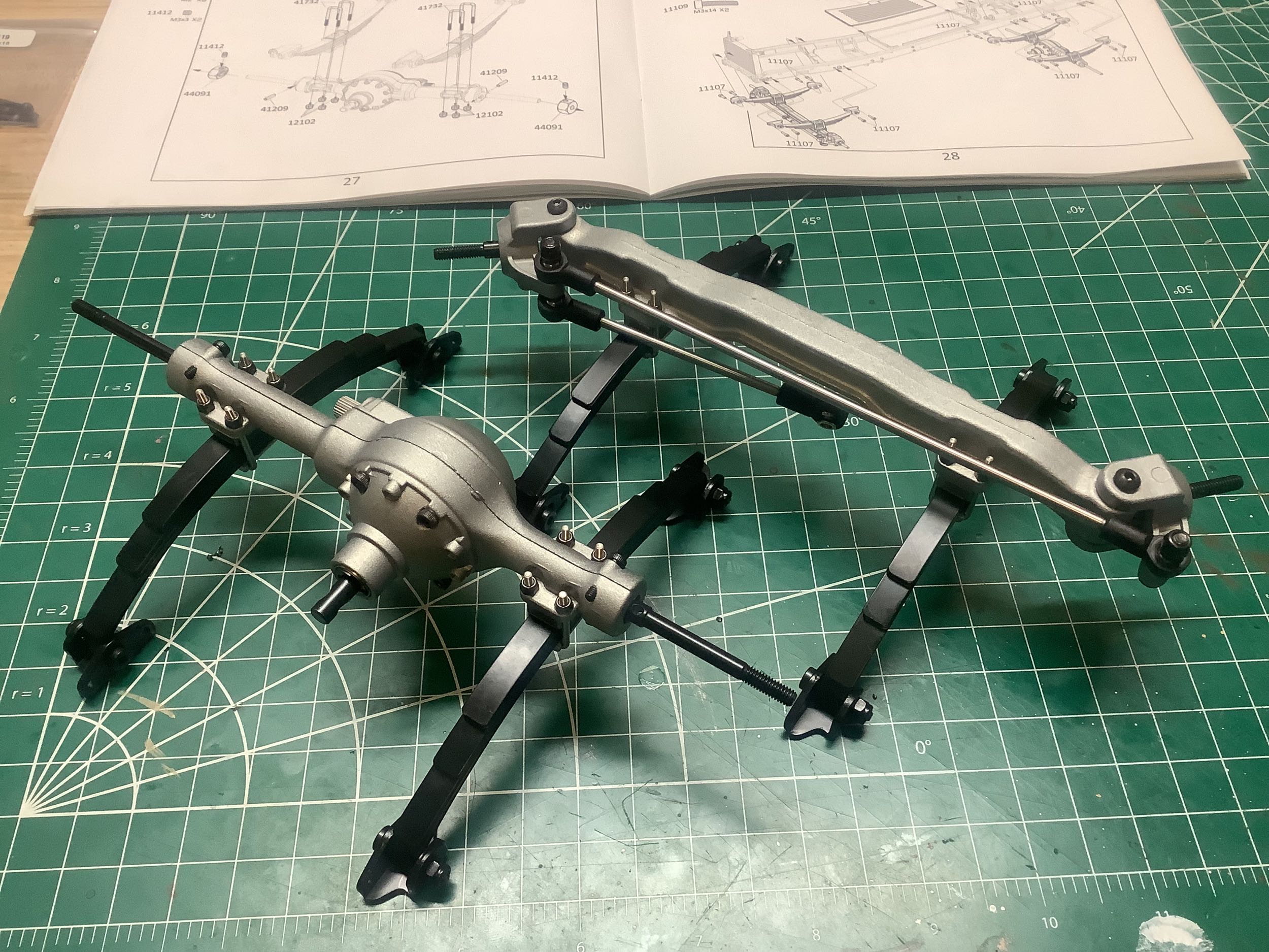
Now both the front and rear axles are completed with the installation of the leaf springs. The front axle looks a like wider because the rear axle has to accommodate the dually wheels. The overall track width will be the same.
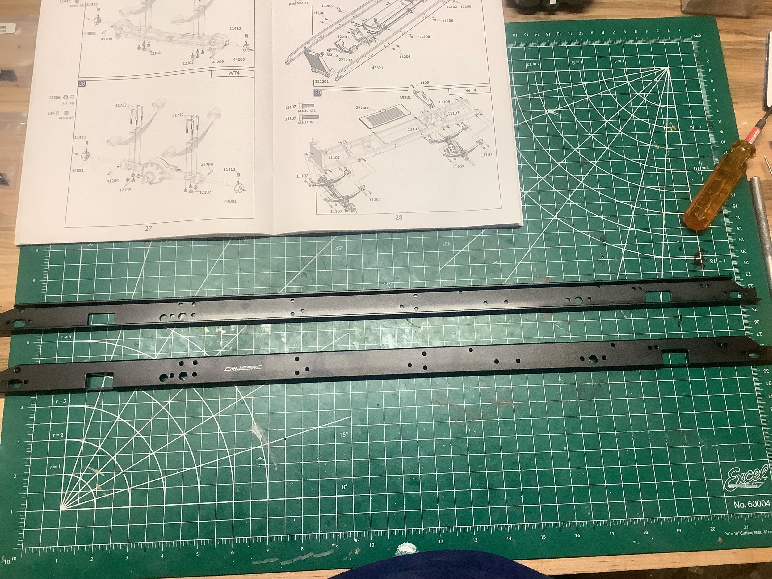
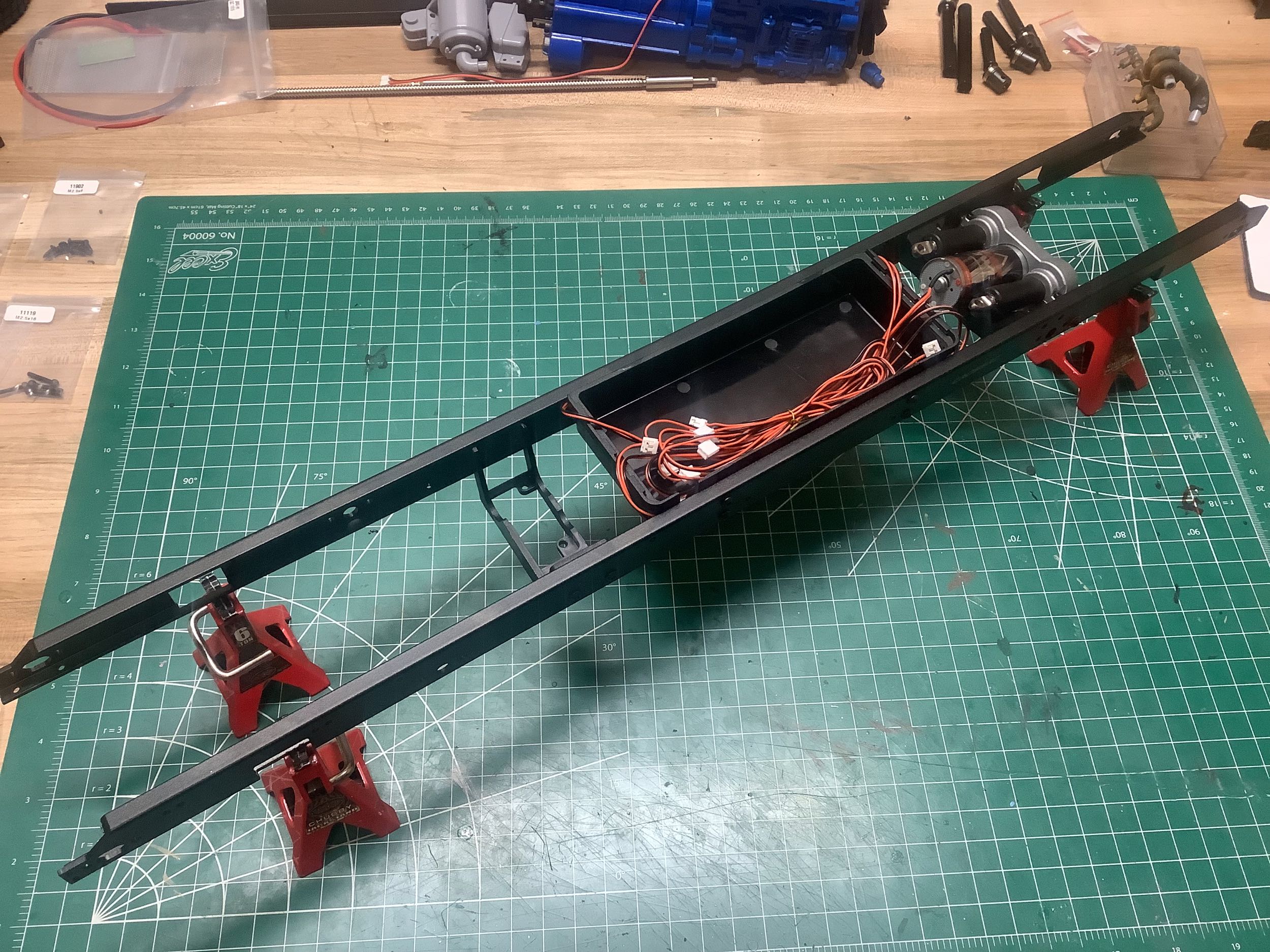
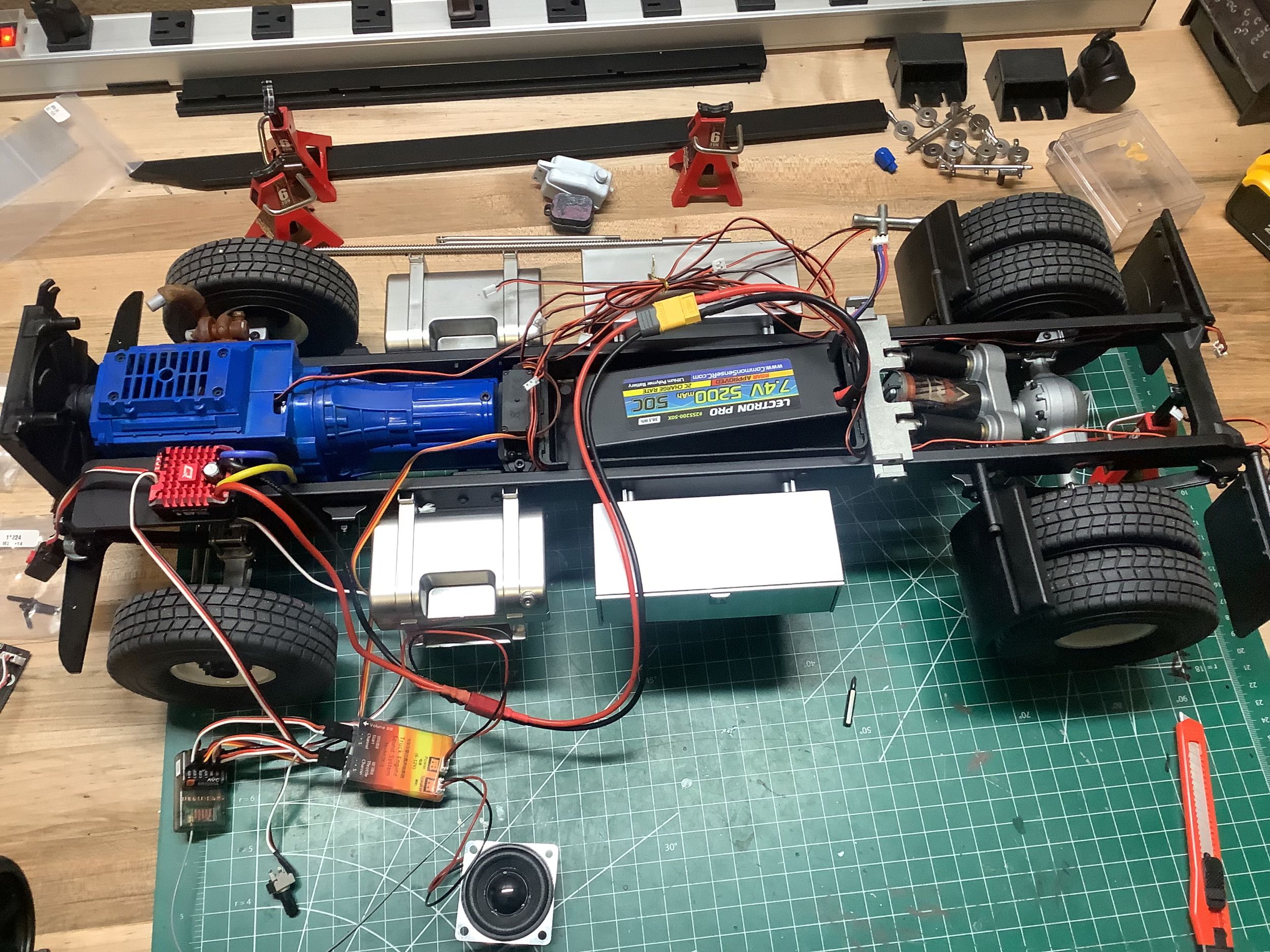
Those are some massive chassis rails. They appear to be aluminum formed plate stock. On the right I've installed the lift motor assembly and the battery box. Many of the wires that will need to run to the back bumper and to the bed need to be run now.
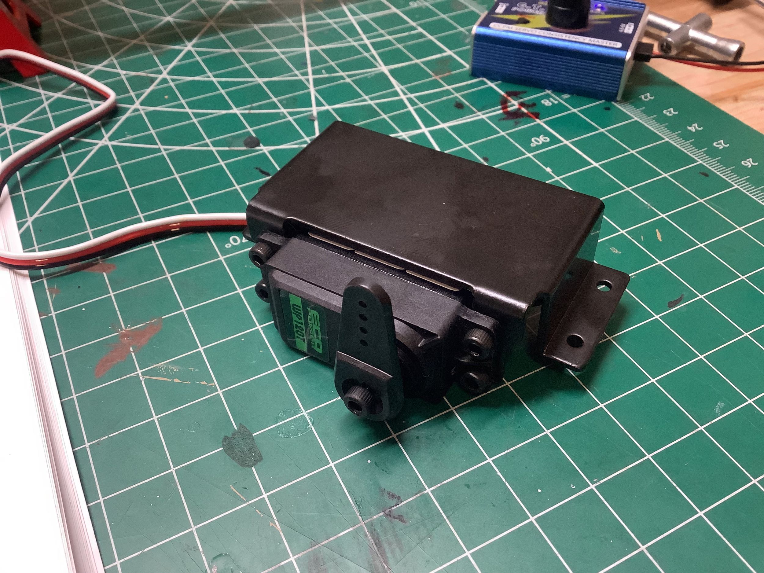
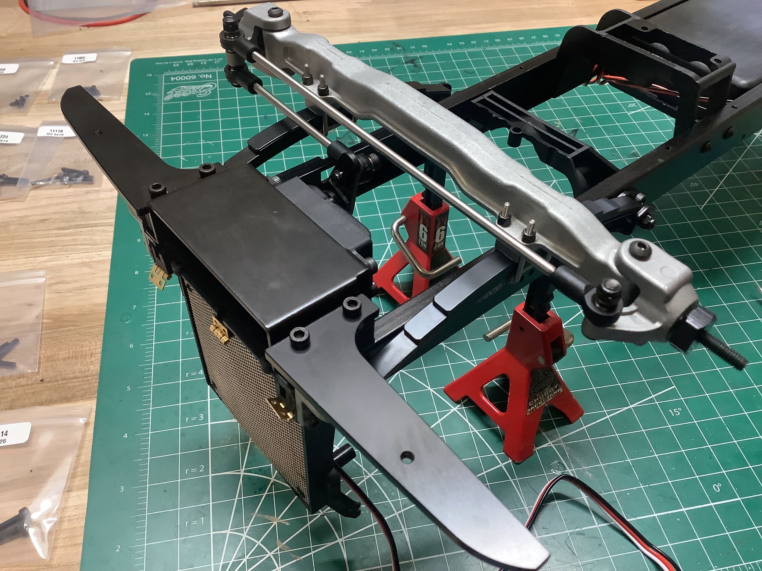
I used a semi-decent high torque steering servo which attaches to this metal bracket. On the right I've installed the servo ahead of the rear axle under the radiator (chassis shown inverted). The front axle has also been installed.
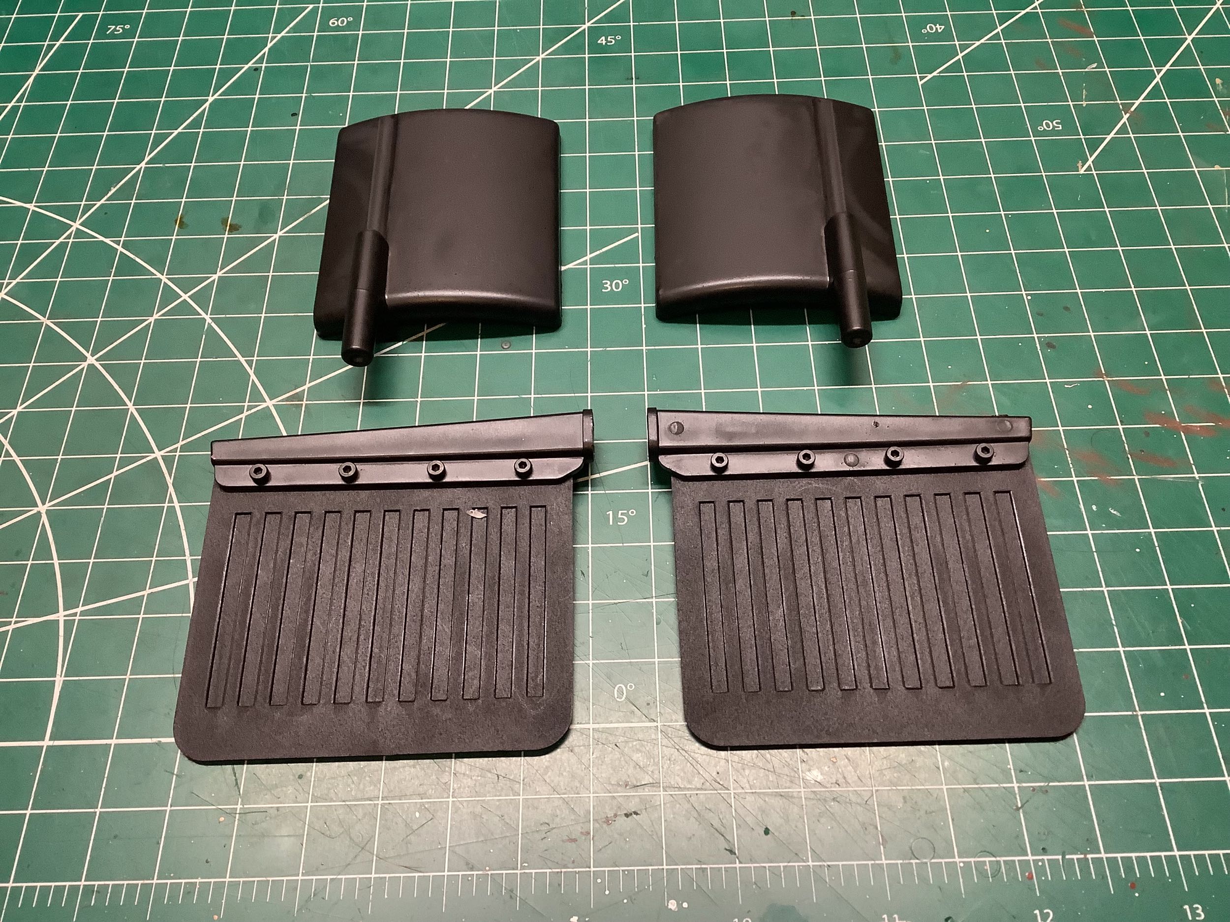
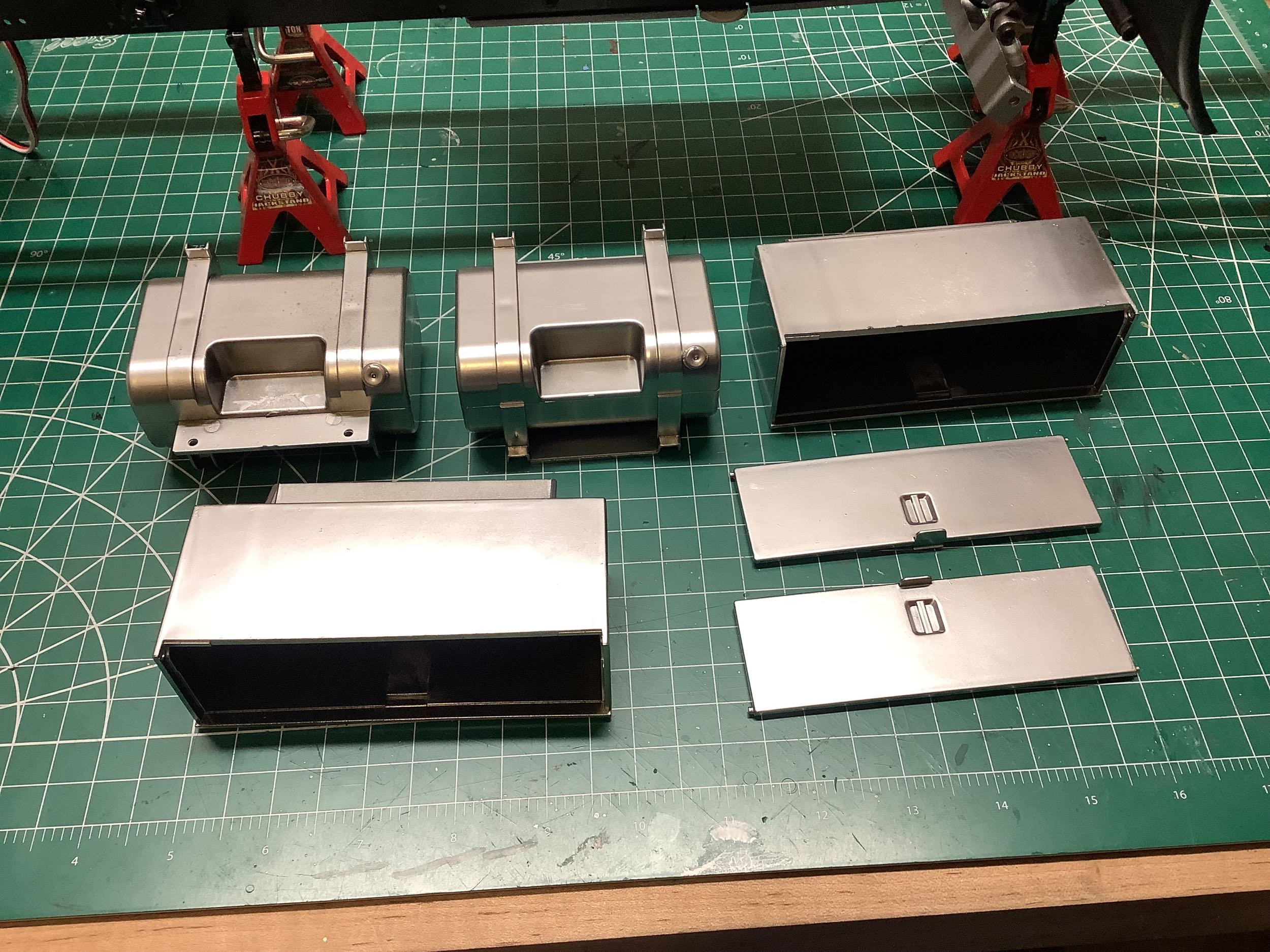
Here are a few more scale details. The plastic fenders go ahead of the rear wheels, and the rubber mud flaps go behind them. The small silver boxes would be fuel tanks on the real truck, and the larger boxes would be for cargo. On the model, these can be used to house various electronics. I used one of them for the receiver, but I put the ESC under the hood.
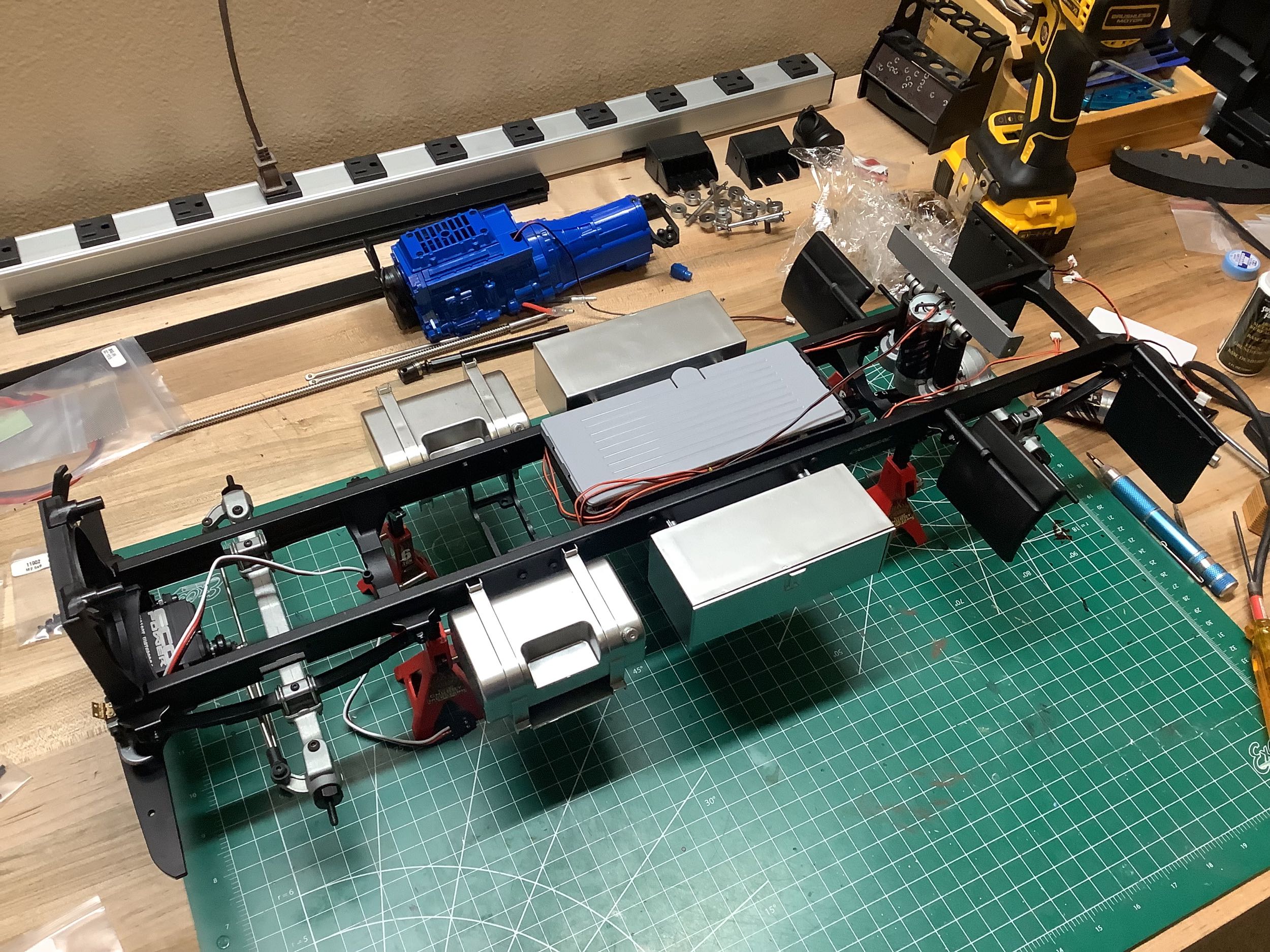
Even though it's just some plastic bits, the chassis looks much more substantial with all these details installed. The rear axle is also now attached.
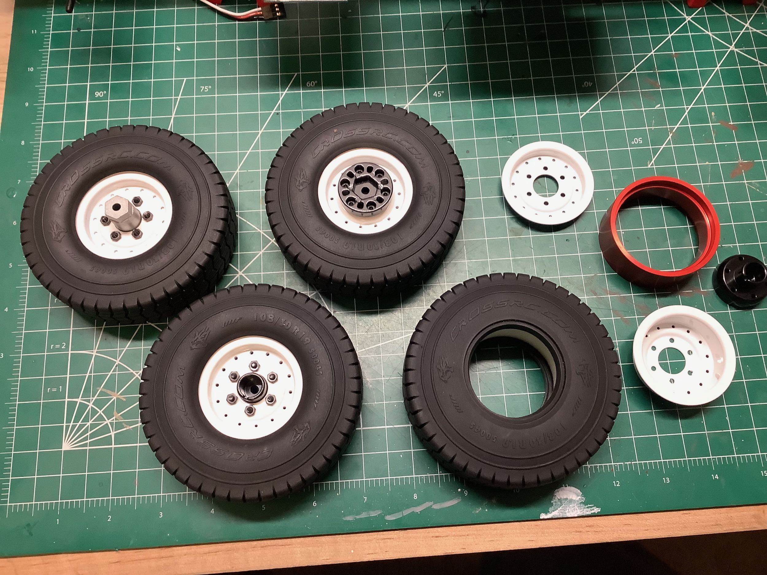
The wheels are all steel beadlocks, and the rear use a dually design so there is a long hub that connects the two together. An inner wheel is shown upper left, and an outer wheel is shown lower left. In the right hand image I've installed the wheels, tires, and gearbox assembly to make a rolling chassis. At this point I was able to try driving it. I put the ESC on a platform next to the engine as shown. I also hooked up the speaker and sound system to try it out.
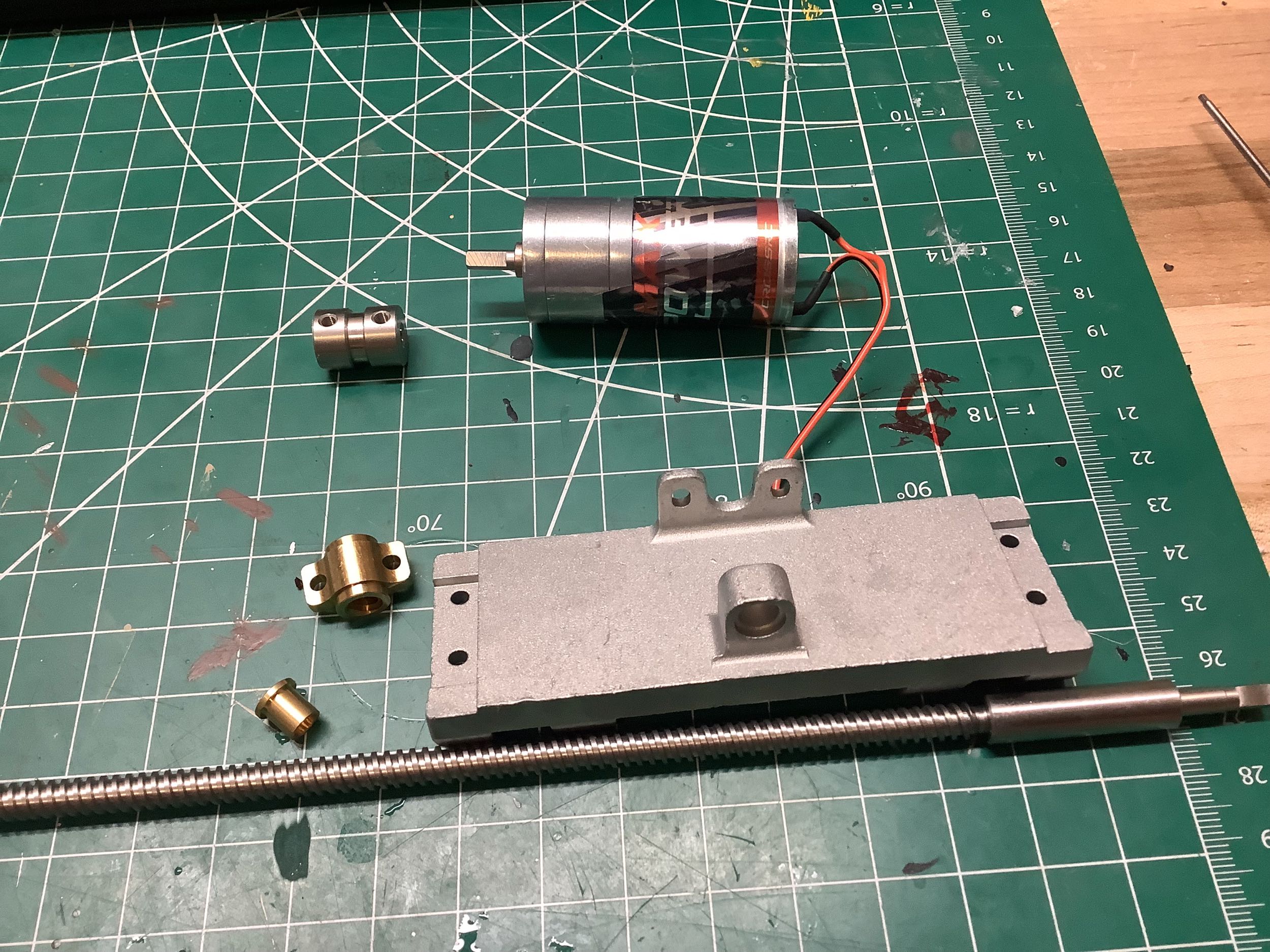
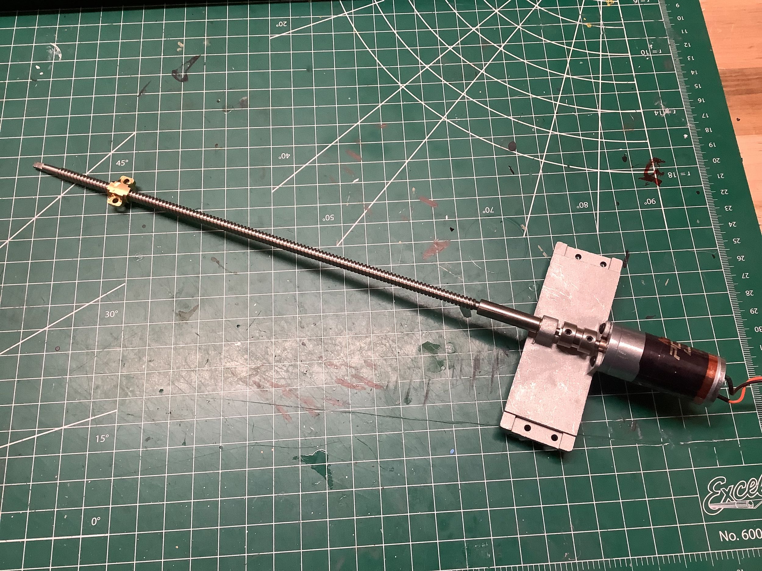
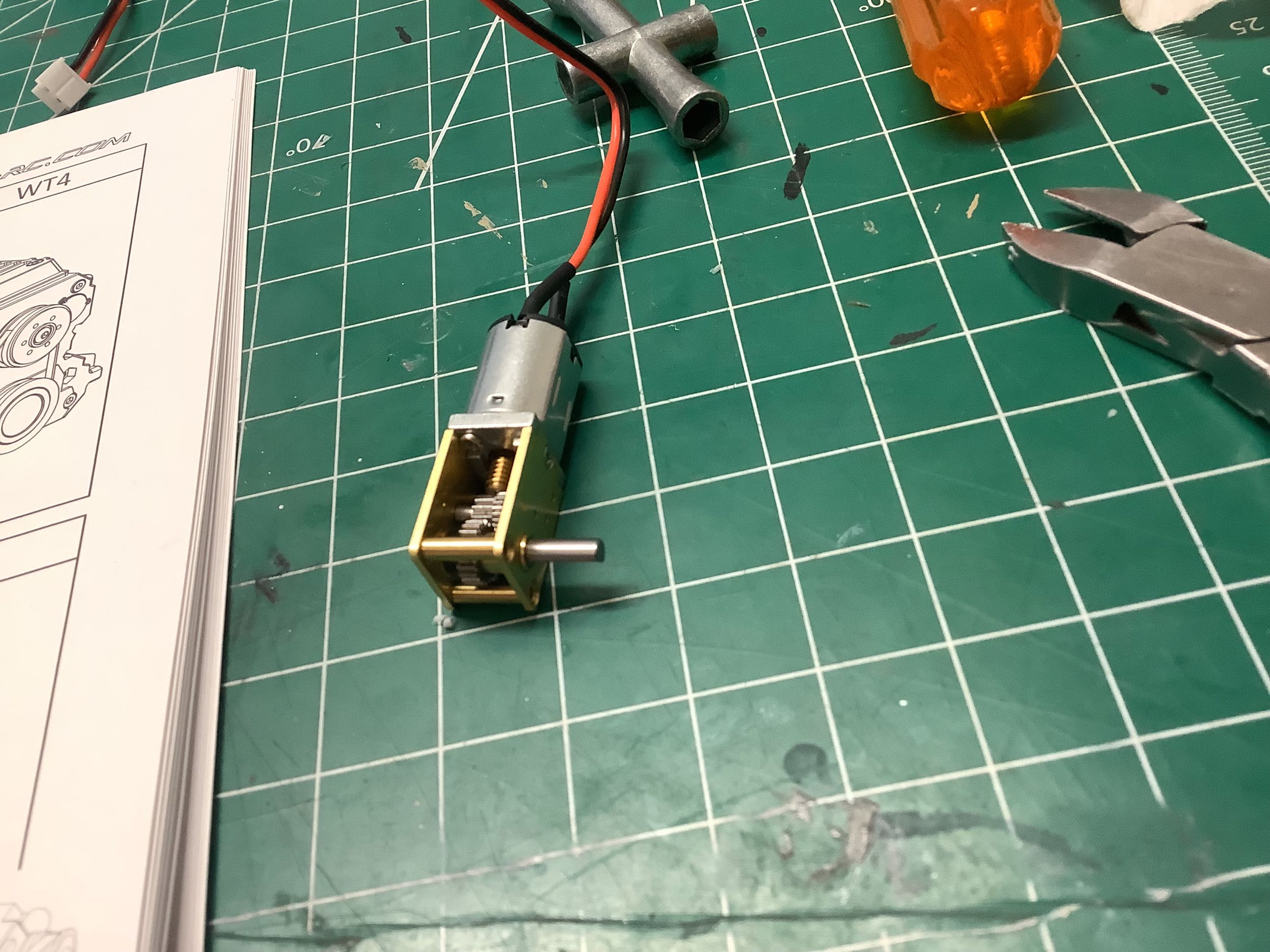
Time to start work on the bed mechanism. You can see that the label is missing from part of this motor. That's because it made noise but the output shaft didn't rotate at all so I cut away the sticker over the gearbox portion, took it apart, and rebuilt it. That was successful for a long time, but eventually the other motor for lifting also stopped working. It turns out there is no drive pin or spline between the final gear and the output shaft; it is just connected with friction. If it starts slipping, then it just won't work. I've rebuilt these motors a dozen times now and they just keep breaking. It is a very poor design. In any case, above you see the acme lead screw which will translate the bed. It is driven directly by the motor. The threaded brass nut shown attaches to the bed and moves with it while the motor and screw stay attached to the tipping carriage.
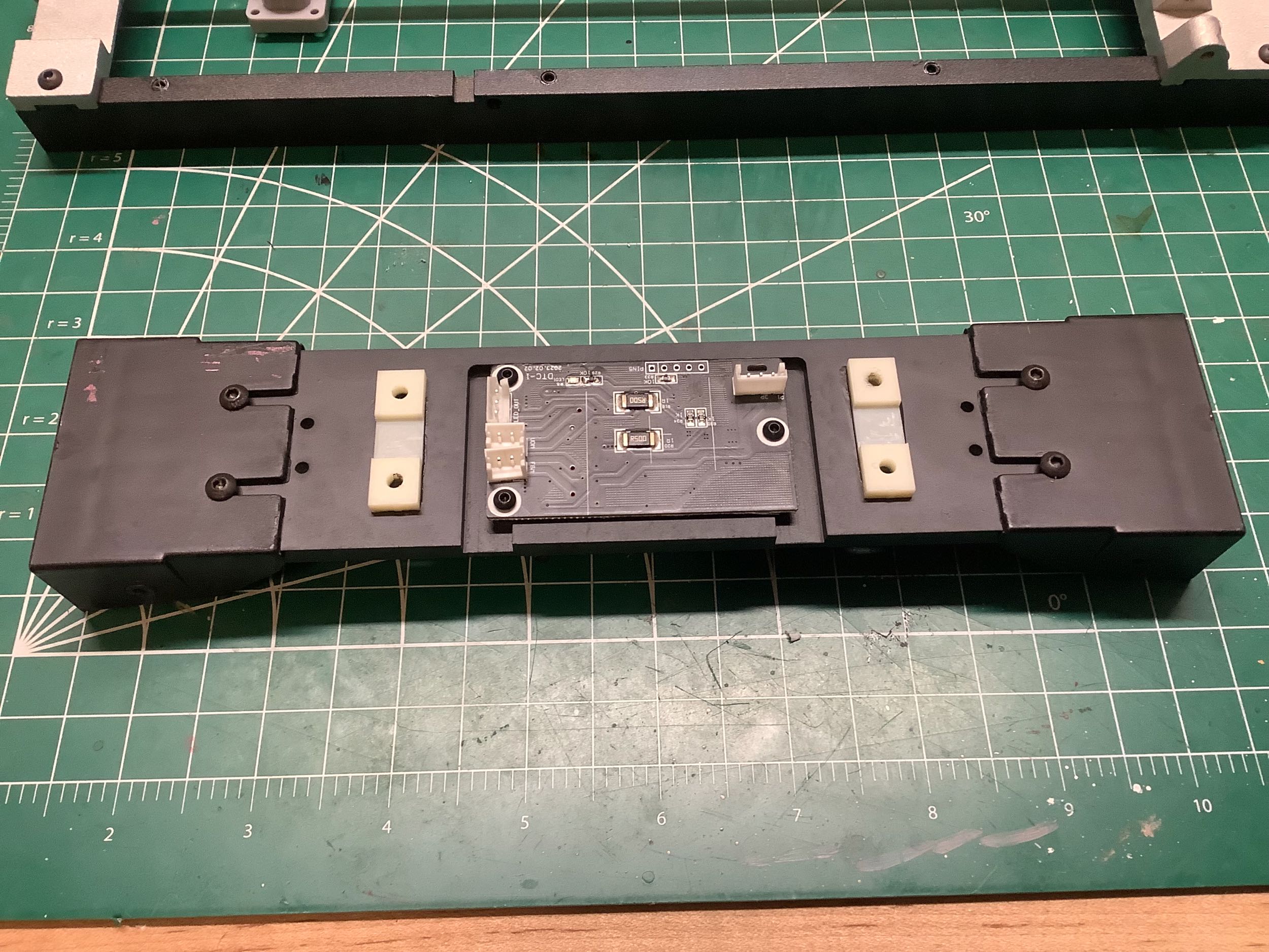
This is the whole tipping carriage. It will pivot on the chassis and be lifted by the lift actuators we assembled earlier. Those rails on the top are tracks. The bed will sit atop them an slide along them on rollers. The rear tail light assembly is attached to this carriage. On the right is the circuit card for the bed motors. It has one input for power and signal and then two outputs to the two motors. It took me a long time to figure out how all this worked with only one channel. The lift motor drives first and it runs until it stalls. This must be triggered some sort of current measurement. After the lift motor stalls, it shuts of and the translation motor starts up. It also drives until it stalls and then shuts down. The same thing happens in reverse. So the lift motor always runs first, and then the translation motor. Since both motors stall every single time, if there is any problem with the friction fit of that final gear it just comes loose. Cool electronic design, bad mechanical design.
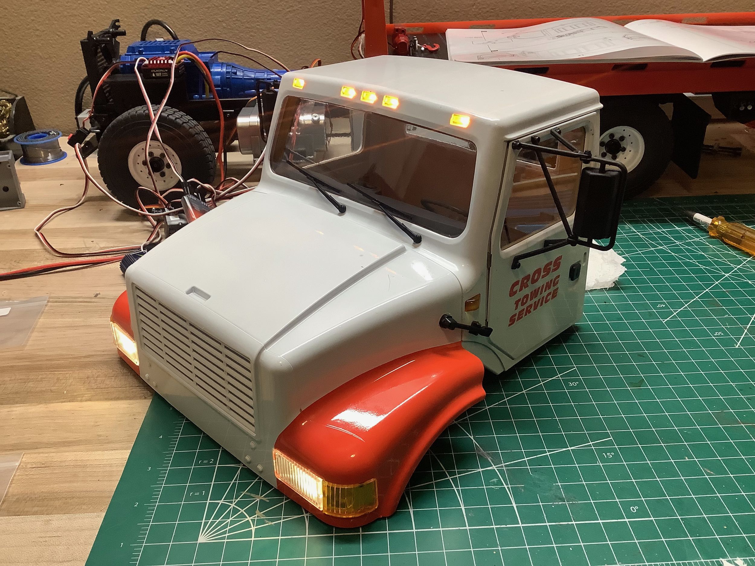
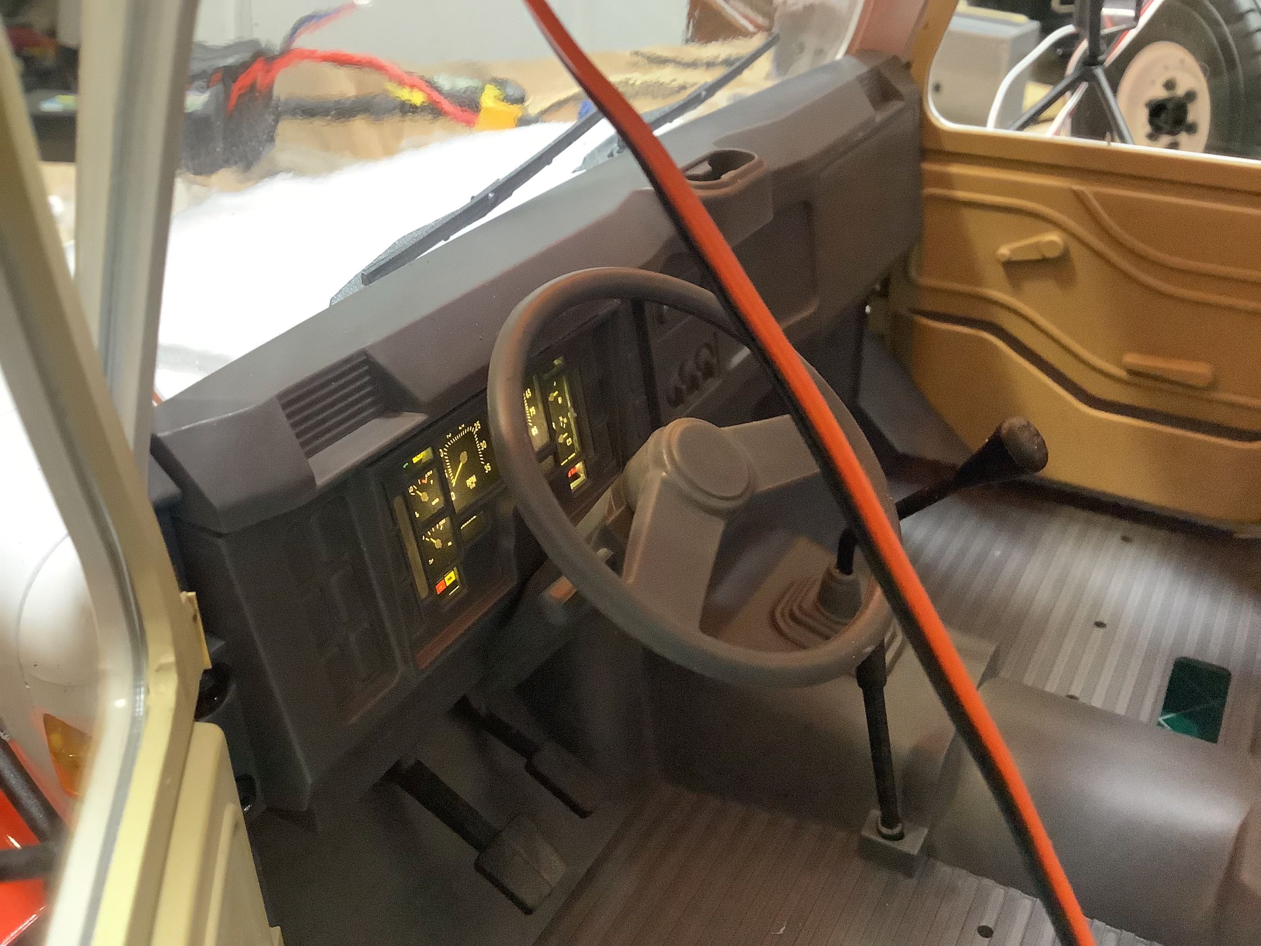
I didn't take any pictures of the body build because it is basically just a plastic model. You can see headlights and roof lights. The hood and doors open, and there are scale wipers and mirrors. On the right you can see the lighted instrument panel. There are also seats but I never installed them because I needed the cab for electronics.
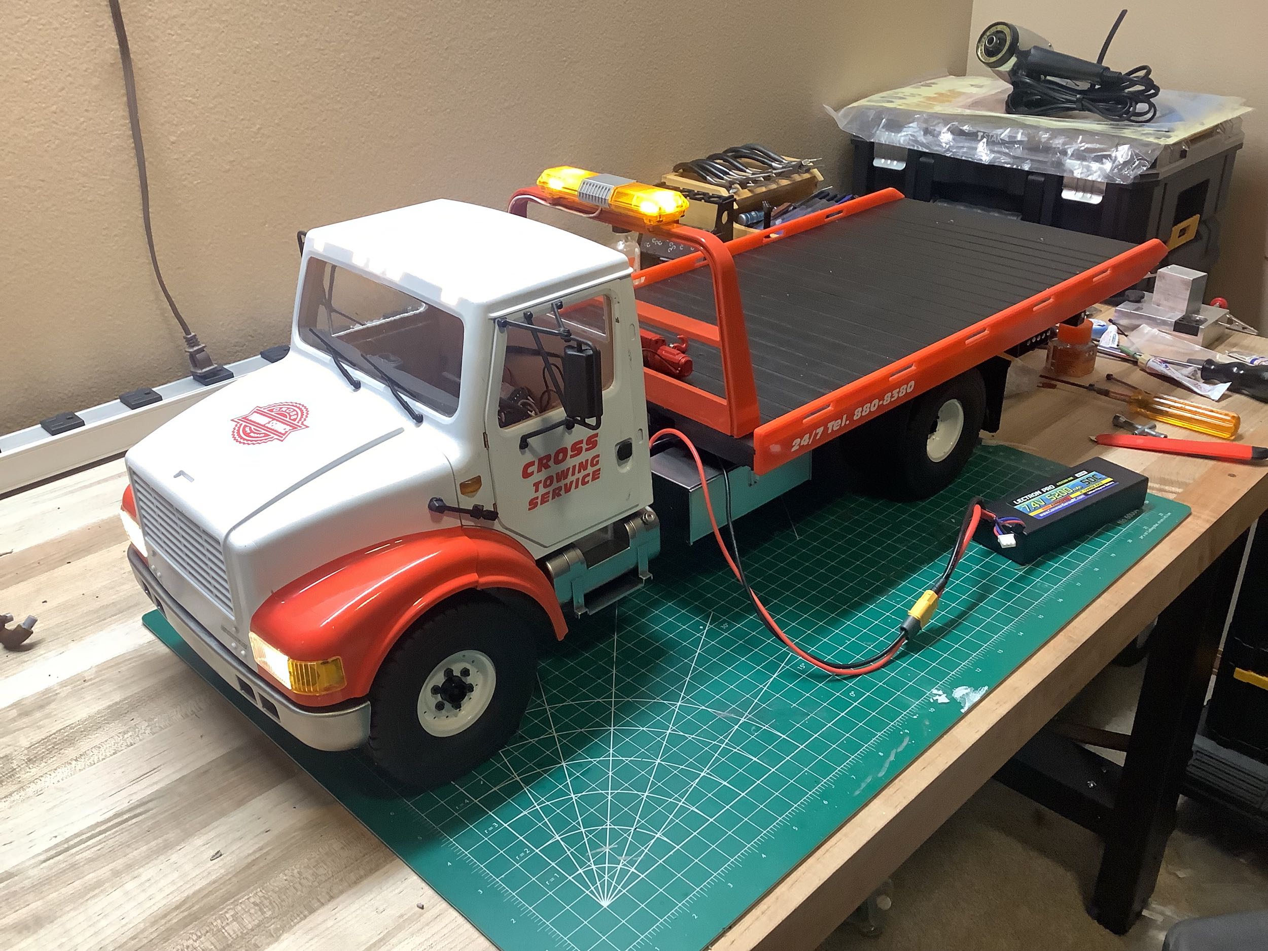
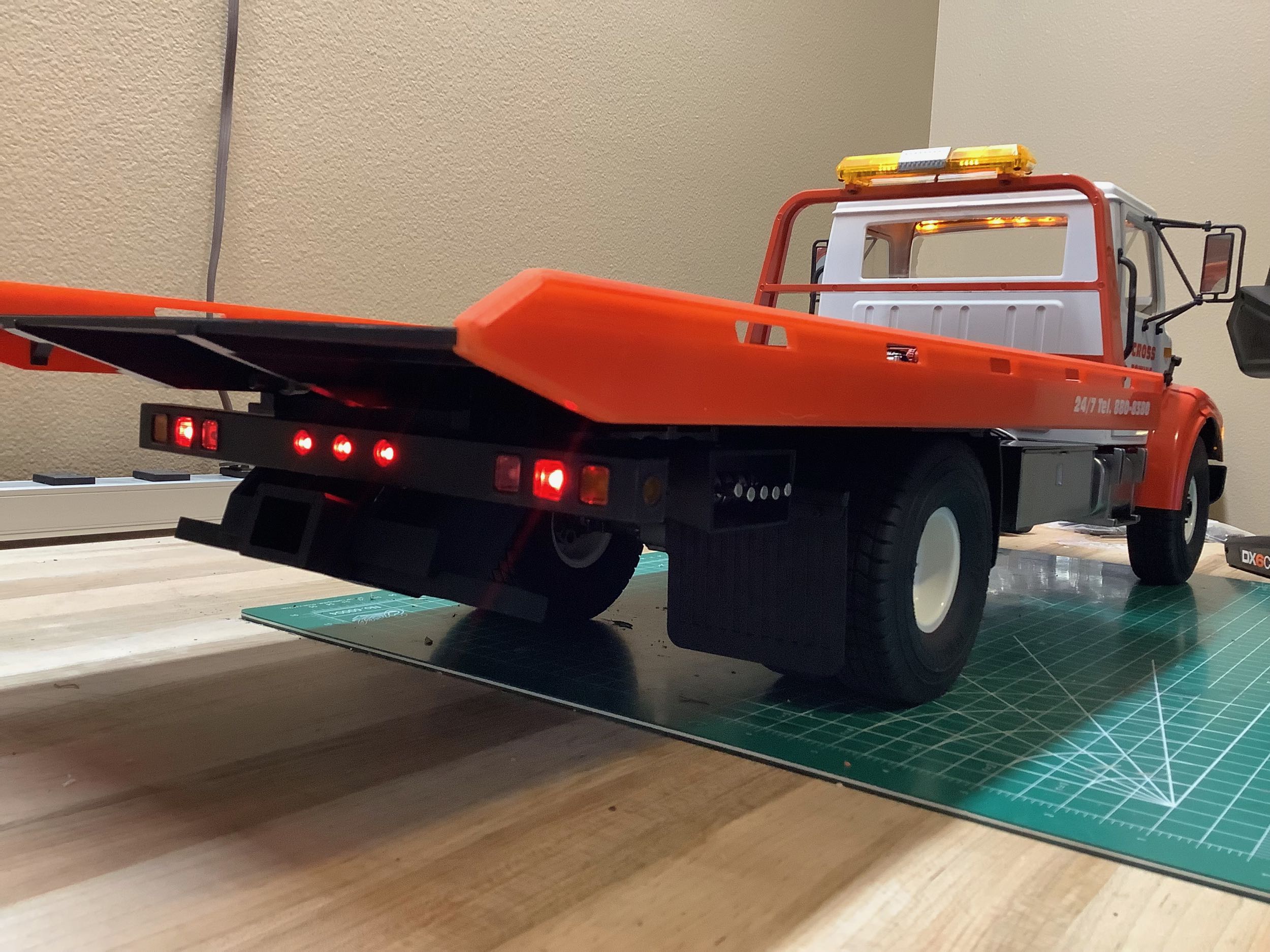
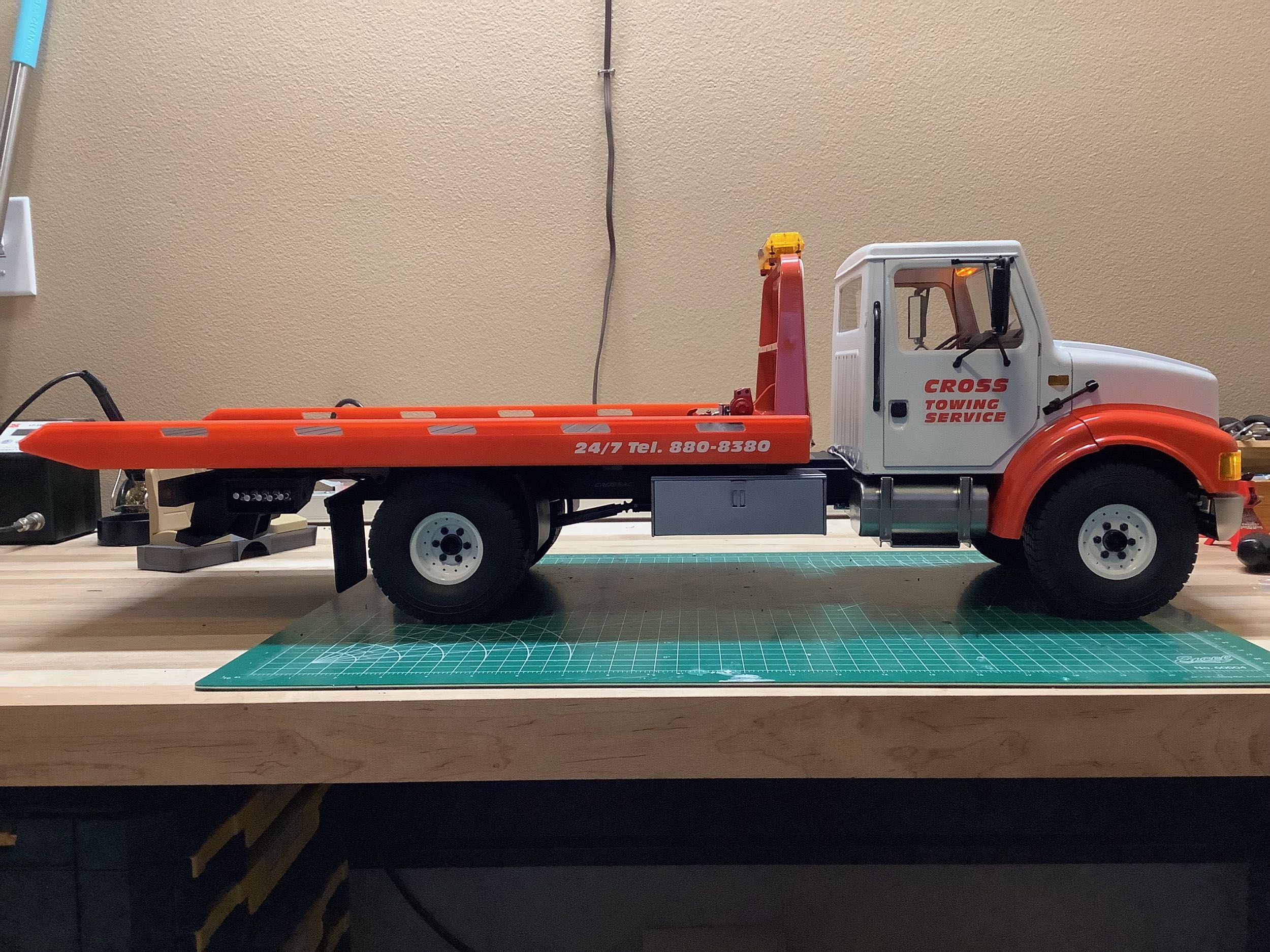
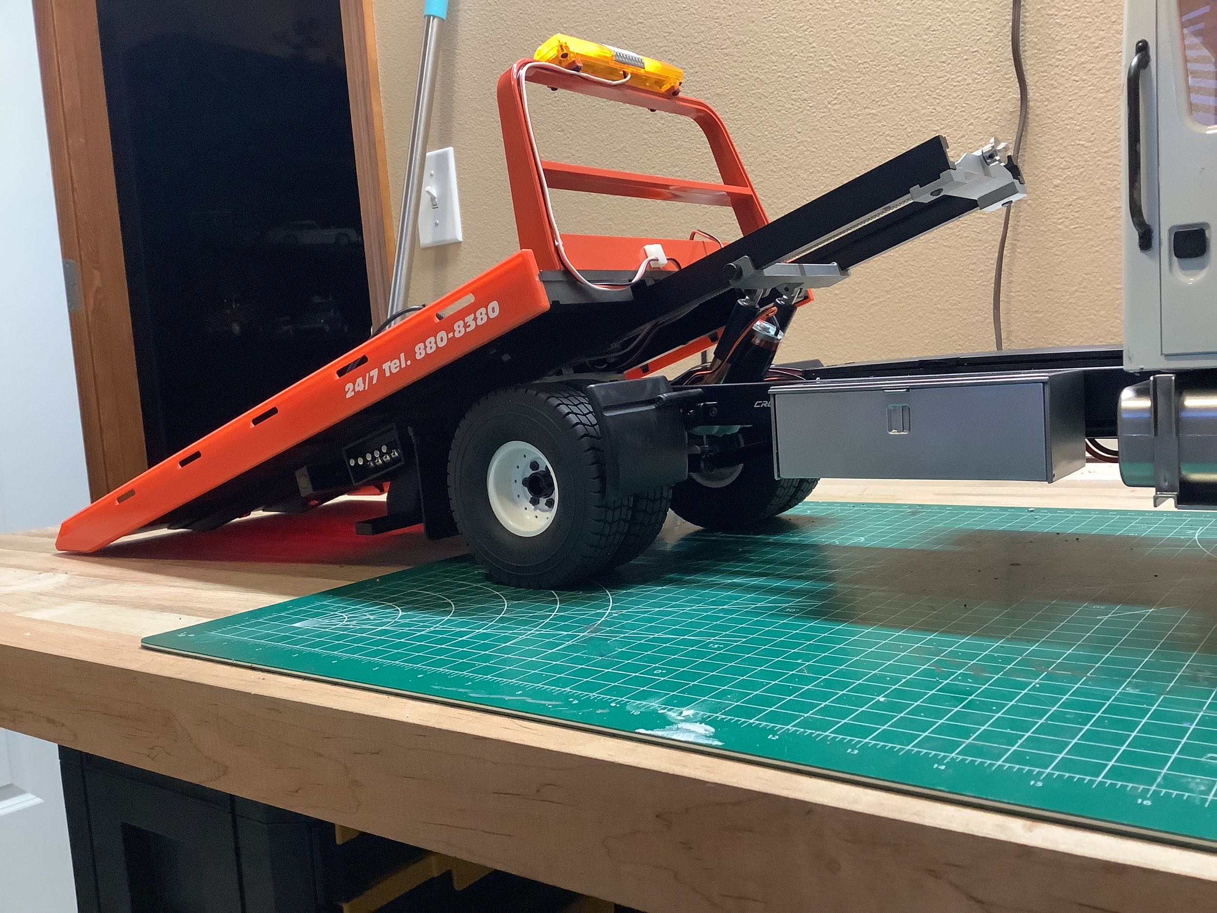
This is the completed truck. I didn't previously discuss the light bar, but it is pretty cool. It cycles through a series of different types of flashes. There are no instructions for where to hide the wires going to the light bar, but I was able to tuck them into the stanchion on which they are installed. There is also a small functional inch at the front of the bed. The wires for both need to hinge with the bed at the rear, and also translate with it. This means they need very long extension wires which are wound around some long rods under the bed to allow them plenty of extra length without binding. It's hard to describe and harder to install. The working tail light include brake lights, turn signals, and reverse lights. Those orange rails along the sides of the bed are just glued on and are not very secure. I wish they were screwed on instead.