
Page 2: Assembling the Chassis
While writing about this build, I am going to concentrate on the
differences between this and the last chassis in the TRF line I built
(the TRF 414M) and also the standard TRF 415 (which I've never built but have studied).
The original TRF 415 carried over the same suspension as the TRF
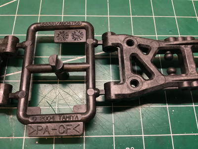
414M, but if you look closely at the picture on the left you'll see "58331"
molded on the sprue for the lower suspension arms. This
reversible arm suspension system began with the TB Evolution IV chassis
in July of 2004, 5 months after the original TRF 415 but 4 months before the
TRF 415MS which first brought it into the TRF line. The rest of
the TRF 415 variants continued with these parts as did many other
chassis including the TRF 416. The 49346
Lightweight Suspension Set allowed this suspension to be installed on
an original TRF 415 or TB Evolution III. The other information on
the sprue reveals that these parts are molded in carbon fiber reinforced
Nylon (polyamide) manufactured in November of 2005. Since the TRF
MSX was released in December of that year, I probably have one from the
very first production batch (or maybe there is only one batch for
limited edition models).
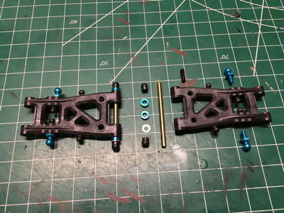
On the right you can see an exploded and assembled view of the parts
for the rear suspension arms. These arms have 3 ball joint holes
on the edge of one side, and the 2 on the opposite side are offset to be
between them. This allows a total of 5 shock attachment positions
by flipping the arms. There are also 4 different plastic balls
for anti-sway bar attachment molded into the arms, although this chassis
uses blue 5mm aluminum balls for both shock and sway bar
attachment. The set screw inserted perpendicular to the arm sets
the down travel stop where it contacts the chassis plate. The
arms pivot on titanium coated hinge pins, and aluminum spacers are used
to control the fit and the precise wheelbase. One useful building
tip to keep in mind is that carbon filled plastic is much stiffer and
more brittle than standard PA, so it is a good idea to tap the threads
before inserting any screws to prevent cracking.
The suspension mounting system shown on the left was first introduced with the 58299 TB Evolution III chassis in 2002. This system originally consisted of blocks labeled X, A, B, C, D, and E which each varied slightly (0.75mm) in width. Mounting your suspension arms using two of the same width blocks resulted in no suspension arm toe, while using two different blocks resulted in 0.5° of toe per letter of difference up to a maximum of 2.5° with the original version. Changing both blocks at the same resulted in a 0.75mm change in track width. It's a very versatile system. The TRF 415 introduced the second generation of these blocks which each include a "1" in front of the letter, as well as expanding the list of options with 1XA-1XD. These blocks are 1mm lower than the original blocks. The "X" can be thought of as a negative sign so the order of width from narrowest to widest is 1XD, 1XC, 1XB, 1XA, 1X, 1A, 1B, 1C, 1D, and 1E for a total variation of 6.75mm. For those of you who care about the math, consider this. If the difference in width is 0.75mm per letter, then that's 0.375mm per side. The length of a hinge pin is 46mm, but the difference between ball centers is 43mm. Doing some quick trigonometry: tan-1 (0.375/43) = 0.5°. Nice job Tamiya.
The picture on the right shows the rear suspension installation which
uses blocks 1XD and 1B resulting in a rear toe of 3° (there is no
additional toe in the uprights). It is pretty easy to see that the
hinge pins are not parallel in the picture. The original TRF 415
had 2.5° of rear toe, 0.5° in the mounts and 2° more in the uprights
(the same uprights used on the TRF 414M).
The two-piece pulleys are pretty annoying. The retaining ring
has to be glued to the main pulley very carefully to avoid getting glue
into the teeth and messing up the smooth travel of the belt. The
TRF 414M used an aluminum pulley with staked retainers. The front
and rear pulleys have the same number of teeth (35T compared to 32T on
the TRF 414M), but the rear pulley (pictured lower) is set up for a ball
differential while the front pulley (pictured upper) is set up for a
one-way. The ball differential shown at the right uses 8 balls
instead of the 10 used on the TRF 414. The drive cups shown for
the TRF 415 MSX have a much wider slot than those from the TRF
415. More on the reason for that later. See those black
plastic rings on the left side of the exploded view? Those have
eccentric holes for the diff bearings and are used to adjust the belt
tension. More on that later as well.
Here's the completed rear ball differential with the eccentric
bearing holders installed over the drive cups. On the right you
can also see the white belt which is a low friction version which was
new to the TRF 415MS and carried forward into the MSX. The picture
also shows four upper bulkheads which are new to the TRF 415MSX (only
two are actually used on the rear. These trap the diff bearings
and allow easy removal of the diff for maintentance without removing the
rest of the bulkhead.
On the left you can see that the rear bulkheads have been installed
over the top of the suspension mounts. The slots for the center
pulley shaft are built into the bulkheads, and the left hand bulkhead
also houses the motor mount. Now the rear differential can be
installed into the rear bulkheads along with the upper caps as shown on
the right.
This side view of the rear drive cups illustrates the belt tensioning method. The bearings are mounted in eccentric plastic mounts. By this I mean that the inner hole for the bearing does not share the same center as the outer ring of the mount; it is offset. There is a tab at the bottom of the mount which fits into one of fourteen scalloped slots on the bulkhead. By rotating the bearing bolder to choose which of these slots the tab fits into, the bearing can effectively be moved forward or backward, tightening or loosening the fit of the belt. These parts were new for the original TRF 415 and are unique to the 415 series, although a very similar system was used later putting the complex scallops on the plastic bearing holder instead of the bulkhead.
Note that the further you rotate the eccentric bearing holders from
center, the greater the component of movement is vertical instead of
horizontal.
The little horseshoe shaped parts shown on the left are stamped 49381
which means they were new for this model. The plastic is
identified as glass filled POM (Polyoxymethylene), a very unusual
polymer for Tamiya. This is a very strong, very hard plastic which
makes sense given the application. They are used on the dogbone
ends of the axles as shown on the right. More on the reasons why
further below. The CVD style universals changed slightly for the
TRF 415MS and are carried forward here. The rear axles are steel
and the front are aluminum (both 46mm), presumably because the front
one-way eliminates all braking from the front wheels so they can use
lighter, weaker axles.
The TRF 414M used a combination of 5mm and 6mm balls, with the 5mm
ball cups coming from the TA04. The updated 5mm ball cups shown at
left are stamped 58261
which is the TA04 PRO chassis. They are supposed to be made from a
lower friction material which will last longer. The right hand
picture shows an exploded view of the camber links assembled from these
cups combined with a turnbuckle. The aluminum uprights shown are
standard on the TRF 415MSX replacing the plastic parts of the MS.
Note that the aluminum uprights have no built-in toe angle while the
older plastic parts included 1° of rear toe.
Now the rear hub assembly can be added to the rest of the rear
suspension as shown. The threaded screw pin from the TRF 415MS has
been replaced with a hinge pin secured with a set screw on the
MSX. This avoids having to tap anything into the hard plastic of
the lower suspension arms. While I understand the desire to
eliminate the older E-clip secured design, the MSX solution is much
superior to the threaded screw pin which was only used in a couple of
models.
Here we can finally see the purpose of those horseshoe shaped parts
on the ends of the axle dogbones. The slot in the drive cup is
there because the dogbone needs to be able slide in and out of the cup
as the suspension moves up and down. The classic problem is that
high contact stresses between the pin and the slot gradually dent the
drive cup. Once the dent is present, the dogbone can no longer
slide freely and the efficiency of the suspension is compromised.
By putting the plastic bit between the pin and the slot, the contact
stress can be absorbed by the more resilient plastic and distributed to a
wider area in the slot. In the event the plastic is ever damaged,
it can be easily and cheaply replaced to keep everything operating
smoothly. This clever solution requires a wider slot in the drive
cup so it can't easily be swapped into older models. This basic
design (with updated materials) is still used on Tamiya's high end
chassis today.
Whereas the TRF 414M came with three different spur gear options, the
TRF 415 line comes with a single 102T 0.4mod gear. The MS version
added the carbon reinforcing plate. The spur gear shaft is
directly coupled to the rear pulley but uses a one-way to drive the
front. The center pulleys have 16 teeth for an overall belt ratio of 35:16 = 2.1875:1.
Here's the completed center shaft assembly. The TRF 415MS
version used the same shaft design, but it had to be assembled in-situ
by passing the shaft through the bulkheads. The MSX version can be
assembled outside the chassis and inserted as a unit, then held in
place by the upper brace shown on the right. This is a major
maintenance improvement.
The front aft suspension mount is installed upside down with 3mm
spacers to make room for the belt to pass beneath it. The original
TRF 415 and the 415MS used a specialized bridge mount for the same
purpose, but this achieves the same thing without any unique
parts. The steering posts are also installed at this point which
have less standoff built into them (compared to TRF 415) resulting in
lower steering cranks. The TRF 415MSXX changed to a totally
different steering system, so these posts appear to be used only on this
model.
Normally both front suspension mounts would be the same width
resulting in parallel hinge pins, but in this case the combination of a
1XB and 1B suspension mount means there is -2° of front arm sweep.
Conventional wisdom suggests this is a bad idea, so I don't know why
this chassis is configured this way. The TRF 415 and 415MS used no
sweep angle and, interestingly, the 415MSXX went back to a bridge mount
also with no sweep.
The steering cranks on the TRF 415MSX are the same as on the previous
versions, but the bridge has been moved on top of the cranks instead of
beneath them since the cranks themselves are now installed lower.
The cranks appear to be the same parts from the TRF 414M but with the
longer one swapped to the right instead of the left. The new front
bulkheads are installed in the same step. The TRF 415MSXX changed to a completely different steering crank setup.
Here are the parts for the front one-way which seem unchanged from
the baseline TRF 415, but the method of installation into the bulkheads
using removable caps is new to the MSX. Now the belts are all
fully encapsulated in the chassis.
These steering knuckles are made from carbon filled Nylon and are
stamped as coming from 58331 (TB Evo IV) which is consistent with the
rest of the suspension. These were not used on the original TRF
415 (which used the parts from the 414M) but started with the 415 MS.
The C-hubs are glass filled instead of carbon filled (less strong but
more resilient) and are also stamped with 58331. The kit comes
with two sets of hubs and the manual setup section says they are for
using either 2° or 4° camber angle. It took me forever to figure
out what the actual difference was, partly because the manual is wrong
about how it describes them. If you look closely at the picture on
the right, I've inserted the lower hinge pins and you can see that they
are not parallel to the hubs (I've lined up the hubs with the grid on
my cutting mat to make it more obvious). The pin in the upper part
stamped
"4L" is at a greater angle than the pin in the lower part stamped
"2L". This tends to tip the hubs slightly backward in the lower
suspension arms resulting in a caster angle, not a camber angle. The camber is adjusted by changing the length of the upper links as usual.
These exploded views show how the axle is assembled into the knuckle
(left), and the knuckle installed into the hub via the kingpins
(right). This is all consistent with the 58331 suspension
system. Those clamping 12mm hexes are new to the TRF 415,
replacing the parts from the 414 which were retained with o-rings.
Now we can complete the front suspension my installing the steering
into the lower suspension arms with hinge pins and fixing with the upper
camber links. The completed front suspension is shown on the
right with the steering links also connected.
The original TRF 415 and the MS included 3 different stiffnesses of
anti-sway bars, but the reduction to only a single option was one of the
few downgrades to the MSX. The smaller yellow bar is for the
front suspension and the red is for the rear. In general, red
represents the softest option and yellow is medium. When a blue
option is available, that's the stiffest. The sway bars on the TRF
414M were not very effective because of the loose way in which they
were mounted to the chassis. The 415 kept the same bars and
mounting method, but this was somewhat improved for the MSX with the
addition of stopper collars (the annular disks in the picture
above). More on these in the installed photos below.
Here the anti-sway bars have been installed. The blue stoppers
sit between the plastic brackets which create the pivot points on the
bulkheads. These stoppers keep the sway bar centered and prevent
it from sliding side to side during motion. Note that the front
sway bar has changed shape. The front sway bars beginning with the
TRF 414 and through the 415MS had two bends on each side, but the newer
front bar for the MSX has only a single bend on each side like the rear
bar.
The glorious TRF shocks are largely unchanged from the 414M except
that the threaded shock perch changed from two pieces to one piece with
the 415 and then added an internal o-ring (shown in the exploded view
above) with the 415MS. Why? The TRF 414 used plastic spacers
to change the preload on the shocks. The 414M added two-piece
threaded rings instead. The advantage of having two parts is that
they could be jammed together tightly after adjustment to prevent them
from rotating during the vibrations and impacts of driving. The
415 made this simpler with only a single ring, but now it was
susceptible to unwanted movement. The 415MS solved this problem by
using a longer ring with an internal o-ring groove. The o-ring
interferes slightly with the threads and adds friction. This
provides enough resistance to prevent unwanted movement while still
allowing easy adjustment. The same design is still in use today.
These photos show the parts for the rear shock assembly (left) and
their completed installation (right). There are five possible
shock attachment locations. The outer holes are for the body
posts.
These photos show the parts for the front shock assembly (left) and
their completed installation (right). There are four possible shock
attachment locations.


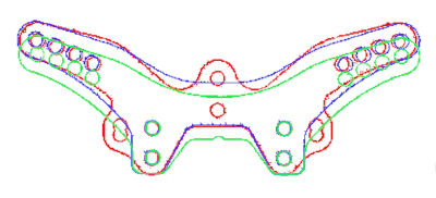
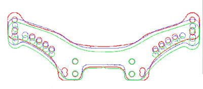
The shock towers changed part numbers with each model update (415MSX
is
different than 415MS is different than 415). It wasn't obvious at
first glance what changed or why, so I prepared the pictures above
comparing them (front tower on the left, rear on the right). Red
is 415, blue is 415MS, and green is 415MSX
(and MSXX). The TRF415 version had some
overlapping holes at the lower edges which is a really bad idea
structurally, but these
holes were unused and there is no indication in the manual as to what
they might be intended for. The MS eliminated these holes and
added
an extra shock position option (rear) as well as lowering the position
of the
body posts (rear). The MSX further lowered both the body post
holes (rear) and
the shock mounting locations. The center holes on the front 415
tower, which were never used for anything and have no identifiable
purpose (except a theoretical and non-existent center body post, were
also eliminated.
The upper deck is another part which changed for the TRF
415MSX. The 415 and 415MS had a much longer upper deck and also a
pair of carbon stiffeners which were completely eliminated from the MSX
because they would have restricted the newly accessible maintenance
access to the differentials. Interestingly, even though the lower
chassis is new for the MSX, it retains the holes for the stiffener posts
which are unused. Perhaps this is to make it backwards compatible
with the MS. A rolling belt tensioner is also installed on top of the upper deck at this point.
I don't like displaying models without any motor in them, but I also
didn't see any reason to spend a bunch of money on a motor which would
never be used so I just put a standard silver can in here as a
placeholder. This model did not come with a pinion gear so I added
my own 39T pinion which is in the middle of the usable range
(23T-50T). In combination with the belt ratio this gives us a
final drive ratio of 35:16 x 102:39 = 5.72:1.
I also threw in a cheap servo to hold the steering in place.
This model uses aluminum servo mounts and a high torque servo
saver. The servo mounts are shorter brackets new for the TRF
415MSX.
The bumper mount and body posts have been the same all the way back
to the TRF 414, but the undercut shape of the foam bumper is new to the
TRF 415 line.