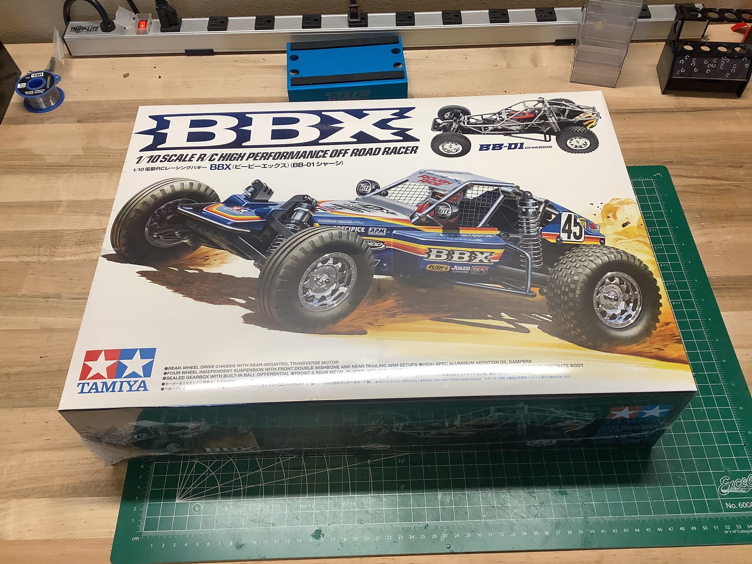
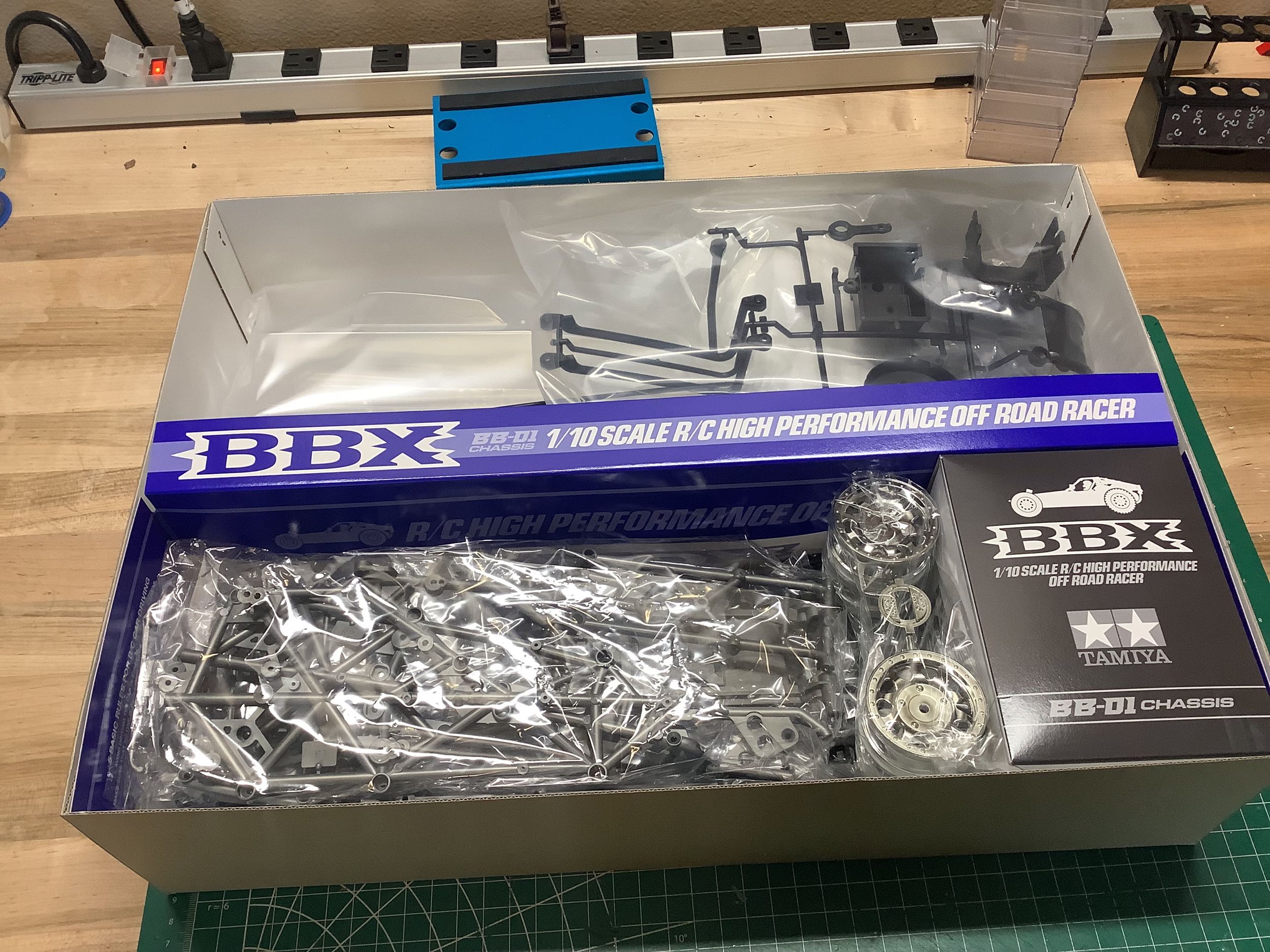
The BBX comes in quite a large box which is separated
on the inside as shown. There are no blister packs, but the body
is in a separate spot from the plastic parts, and the hardware has it's
own inner box. This model gets real, old fashioned, hand drawn box
art!
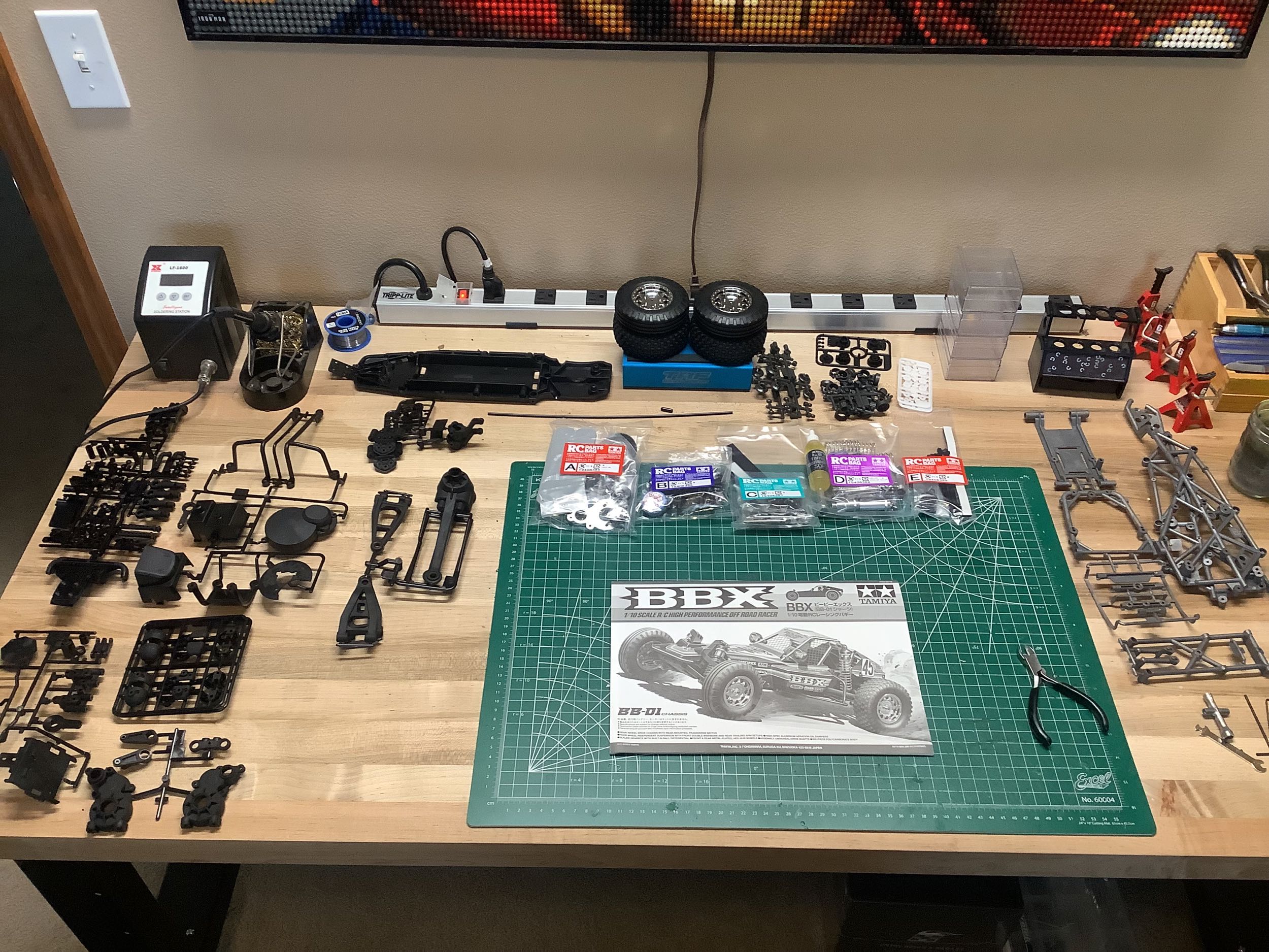
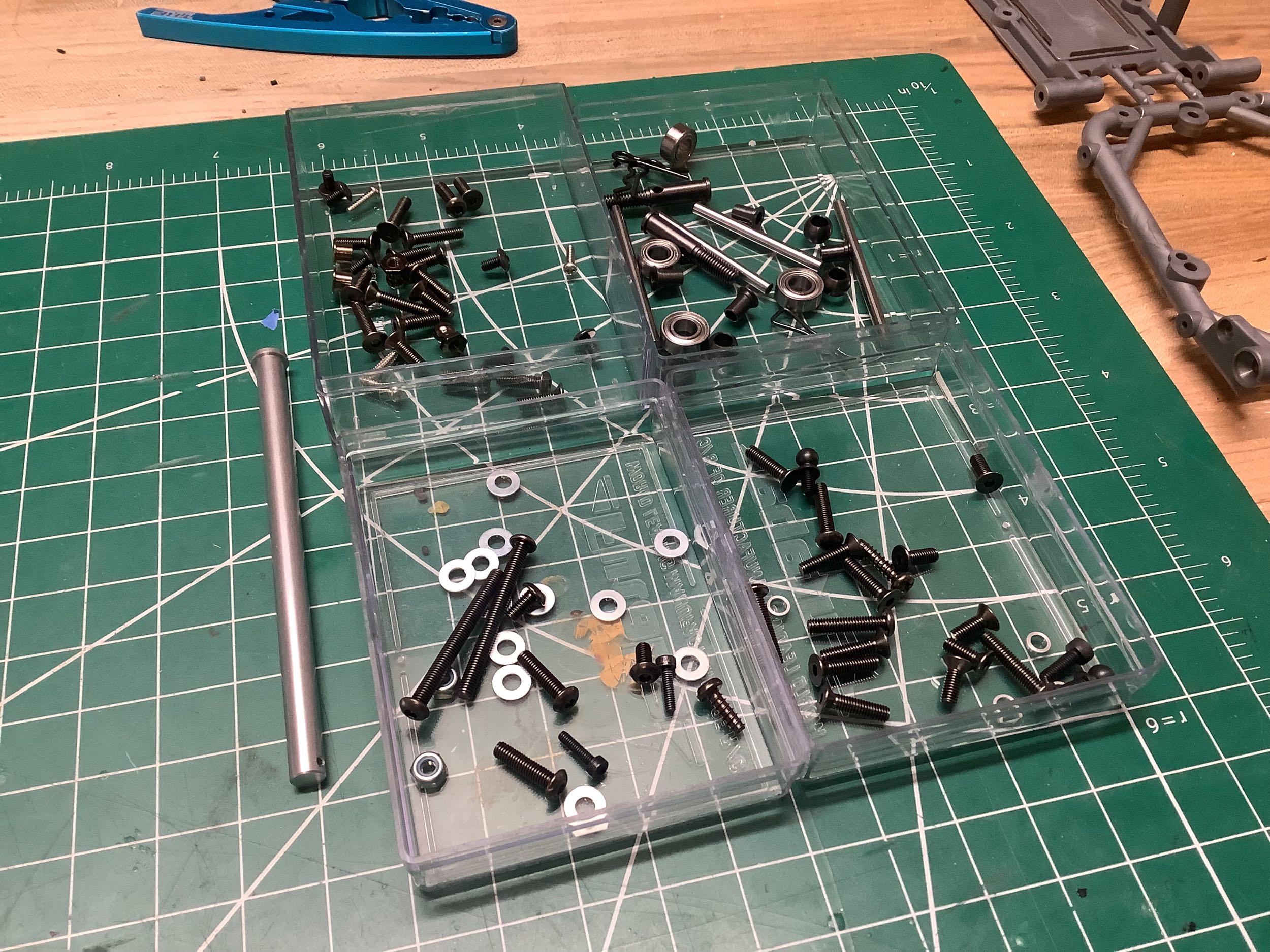
As usual, I laid out all the parts on my build table
as shown. There are five sequential hardware bags and a large
number of plastic parts sprues. Pretty much all of the plastic is
Nylon (polyamide), but most of the structural parts are glass
filled. On the right I show the contents of hardware bag A which
will built the gearbox and motor mount.
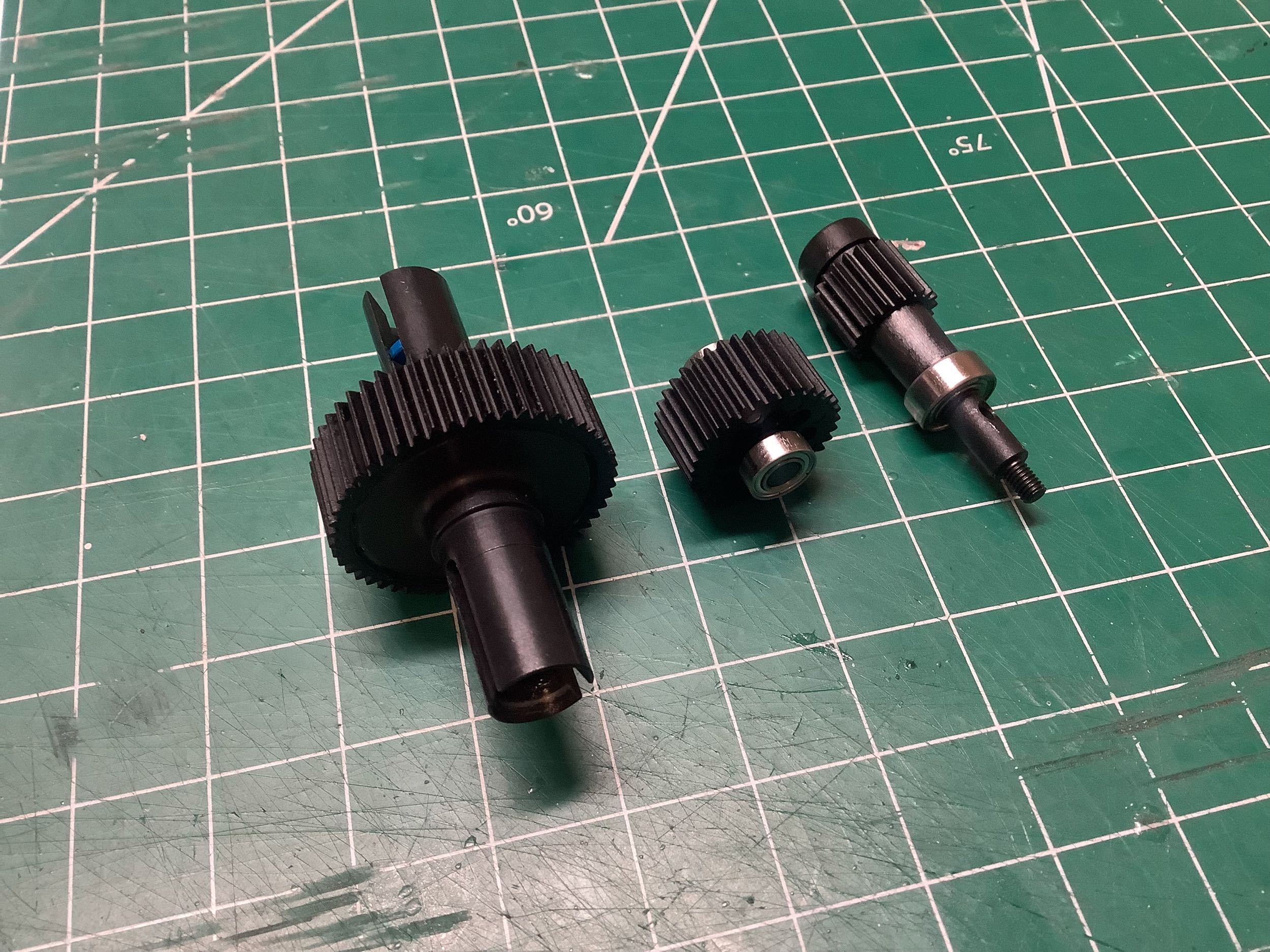
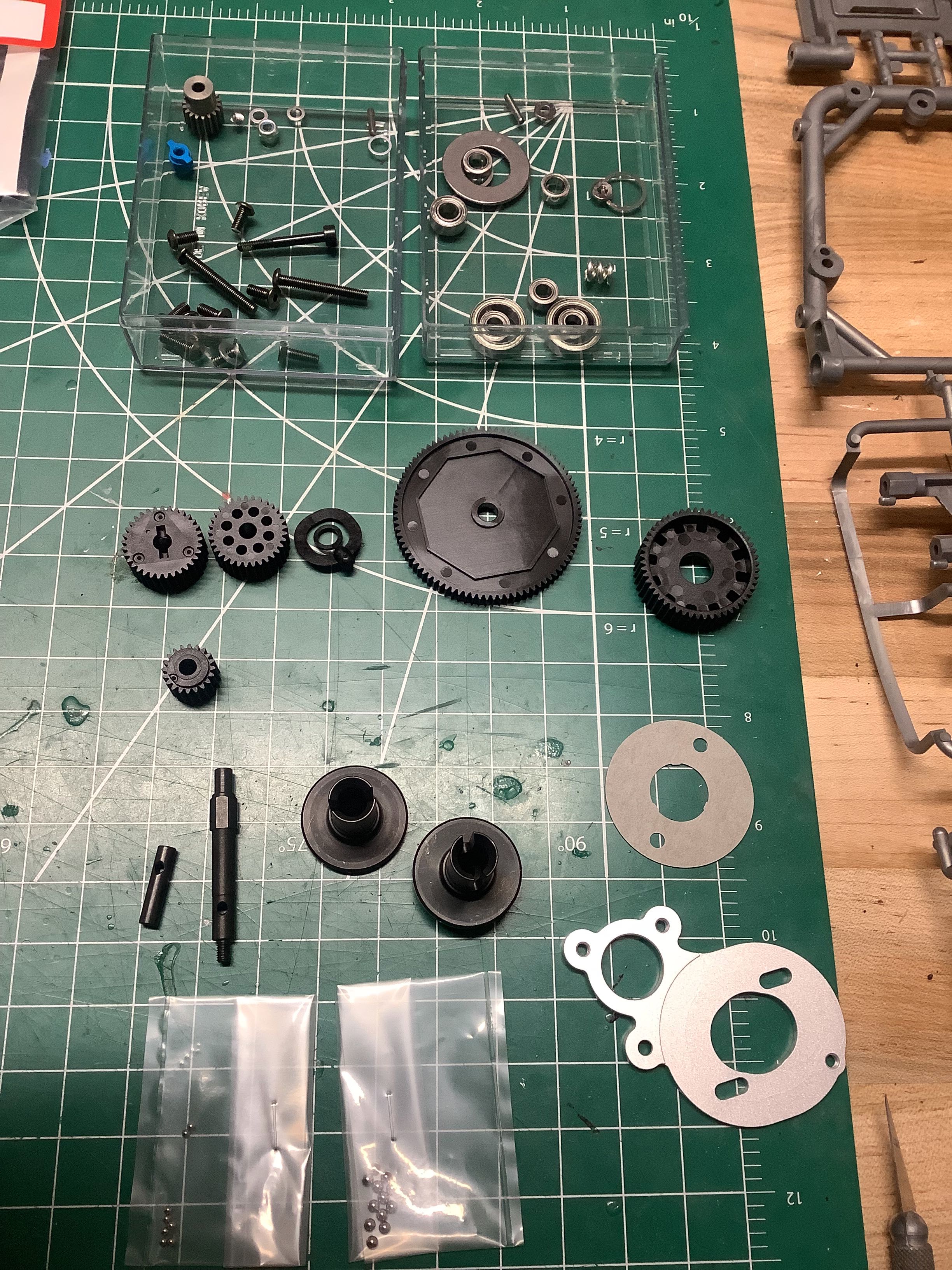
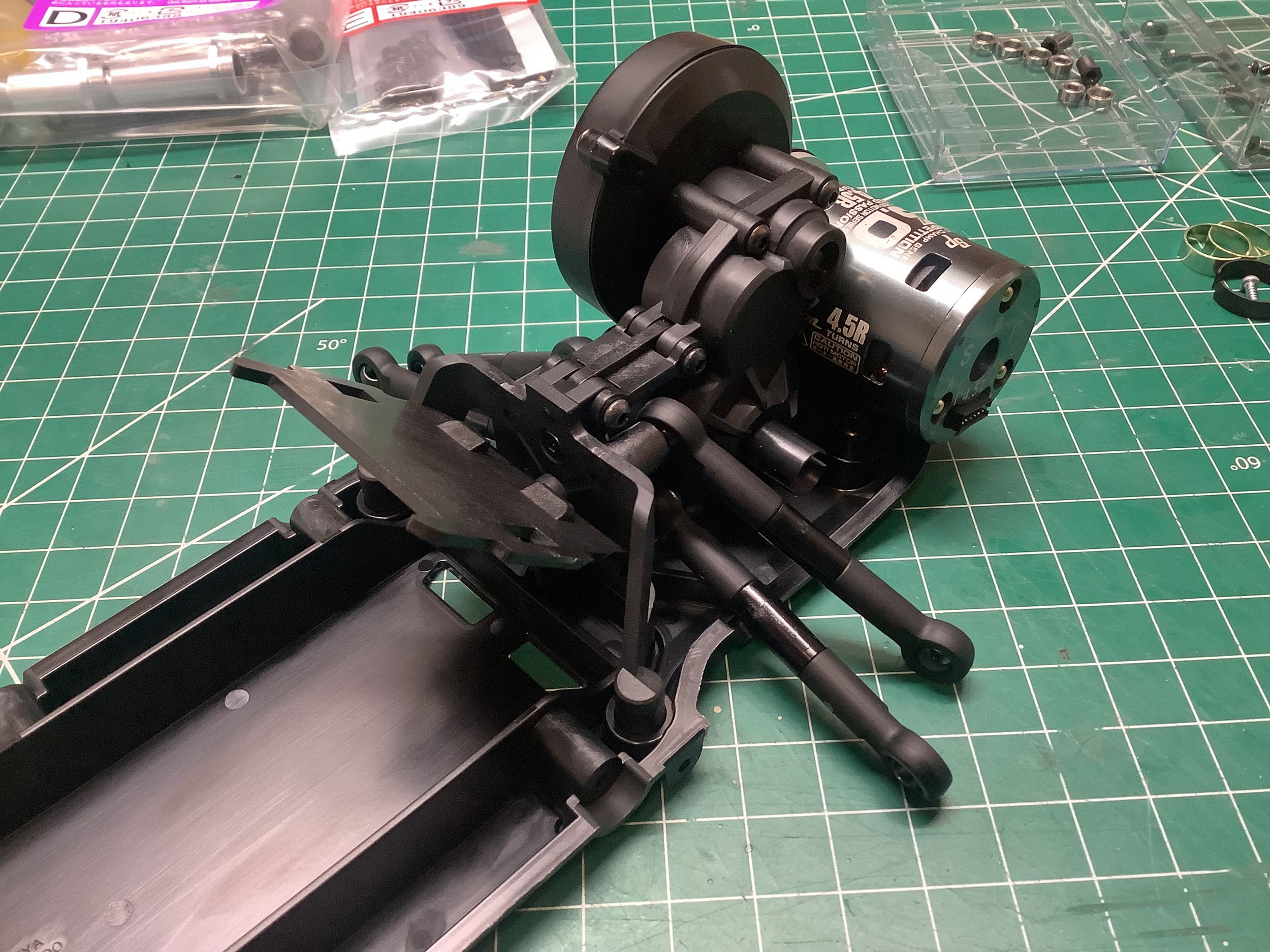
Here are the three shafts making up the gearbox. On the left is
the ball differential which uses Imperial sized balls (3/32") which is
unusual for Tamiya. The center shaft holds the idler gear.
The right hand shaft is the input which will connect to the spur.
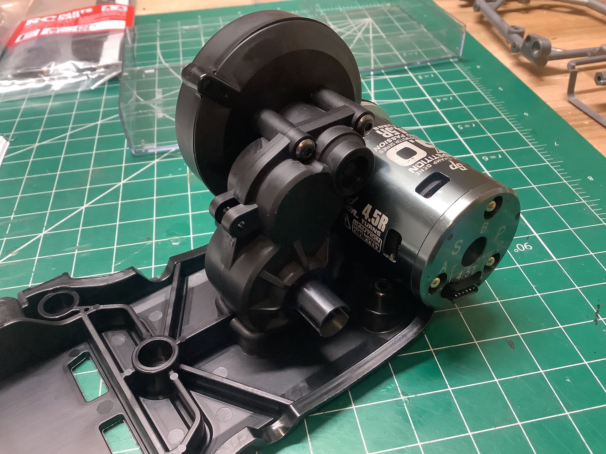
The spur gear is 48p (not metric) as well. On the right I've
installed the gears into the housing and mounted it to the plastic
chassis tub. I've also installed a temporary brushless motor until
the right one arrives.
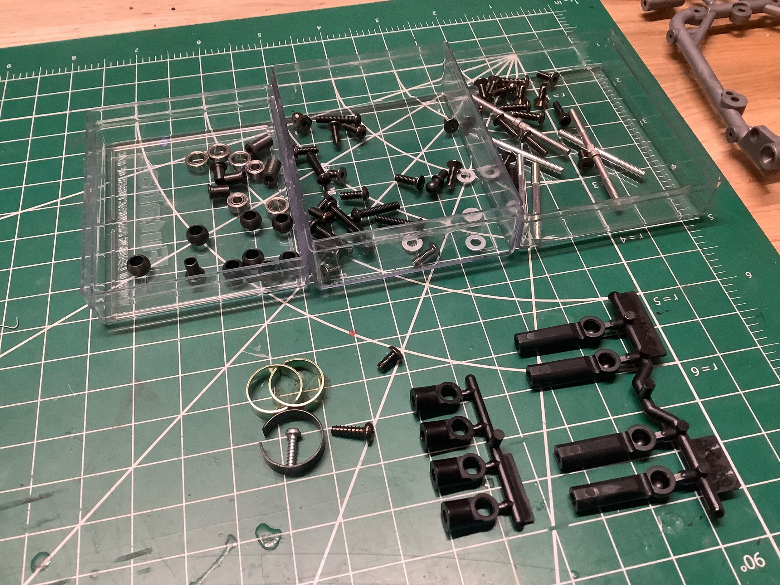
Hardware bag B contains parts for the rear suspension and
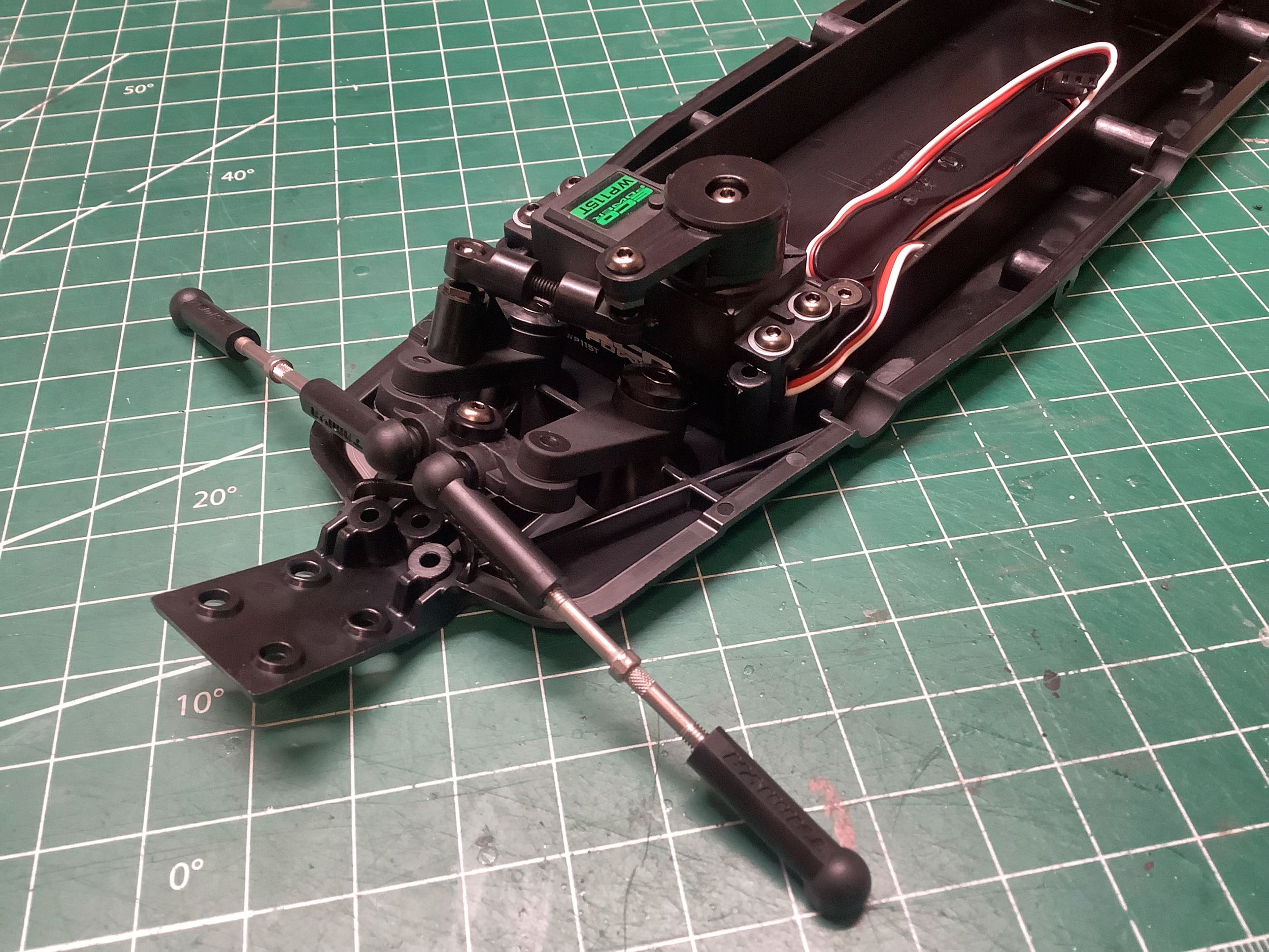
steering. On the right you can see the dual bellcrank steering
linkage installed along with the steering servo. Note that a low
profile servo is required and uses a high torque servo saver. The
steering links are turnbuckles.
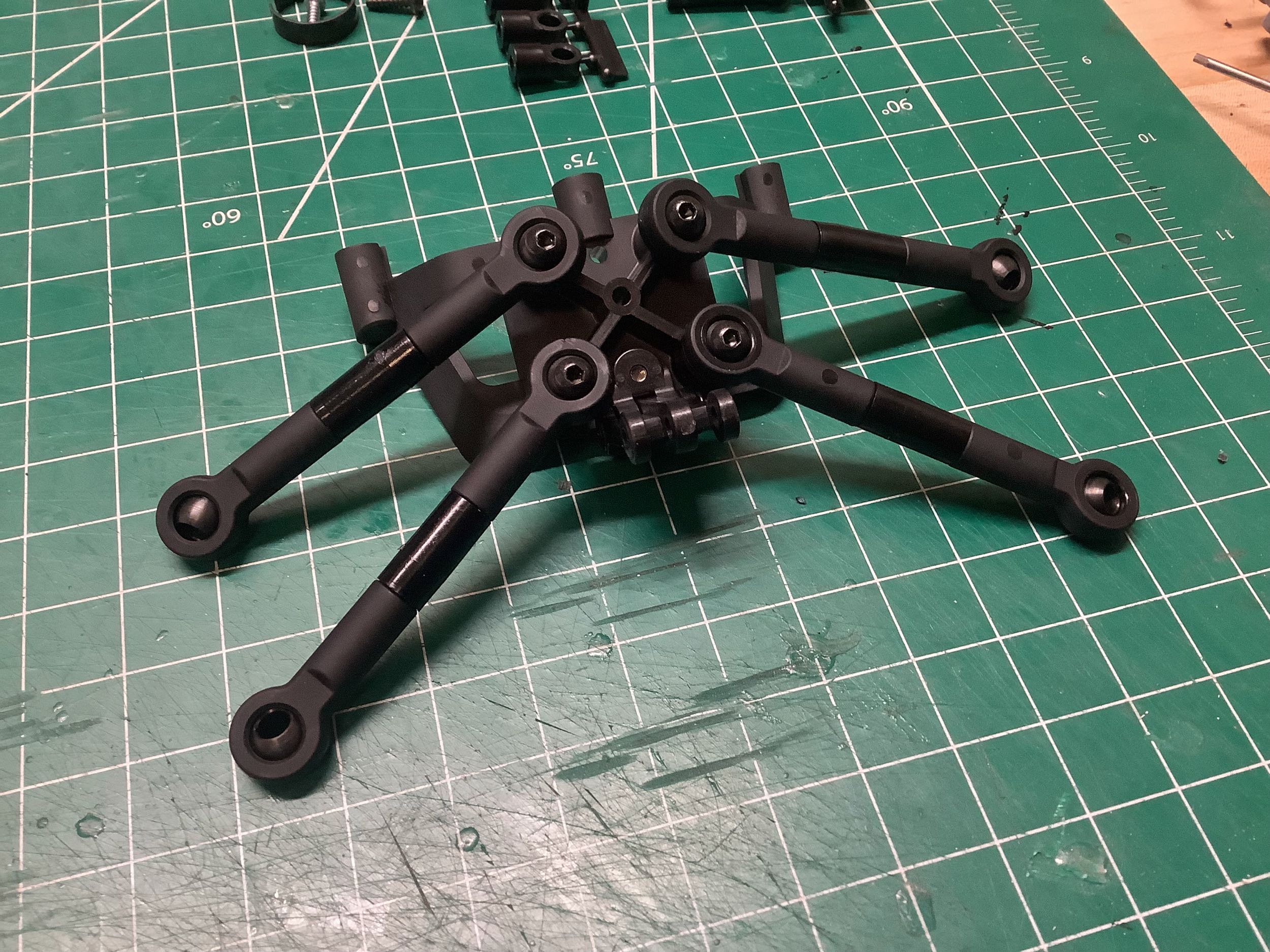
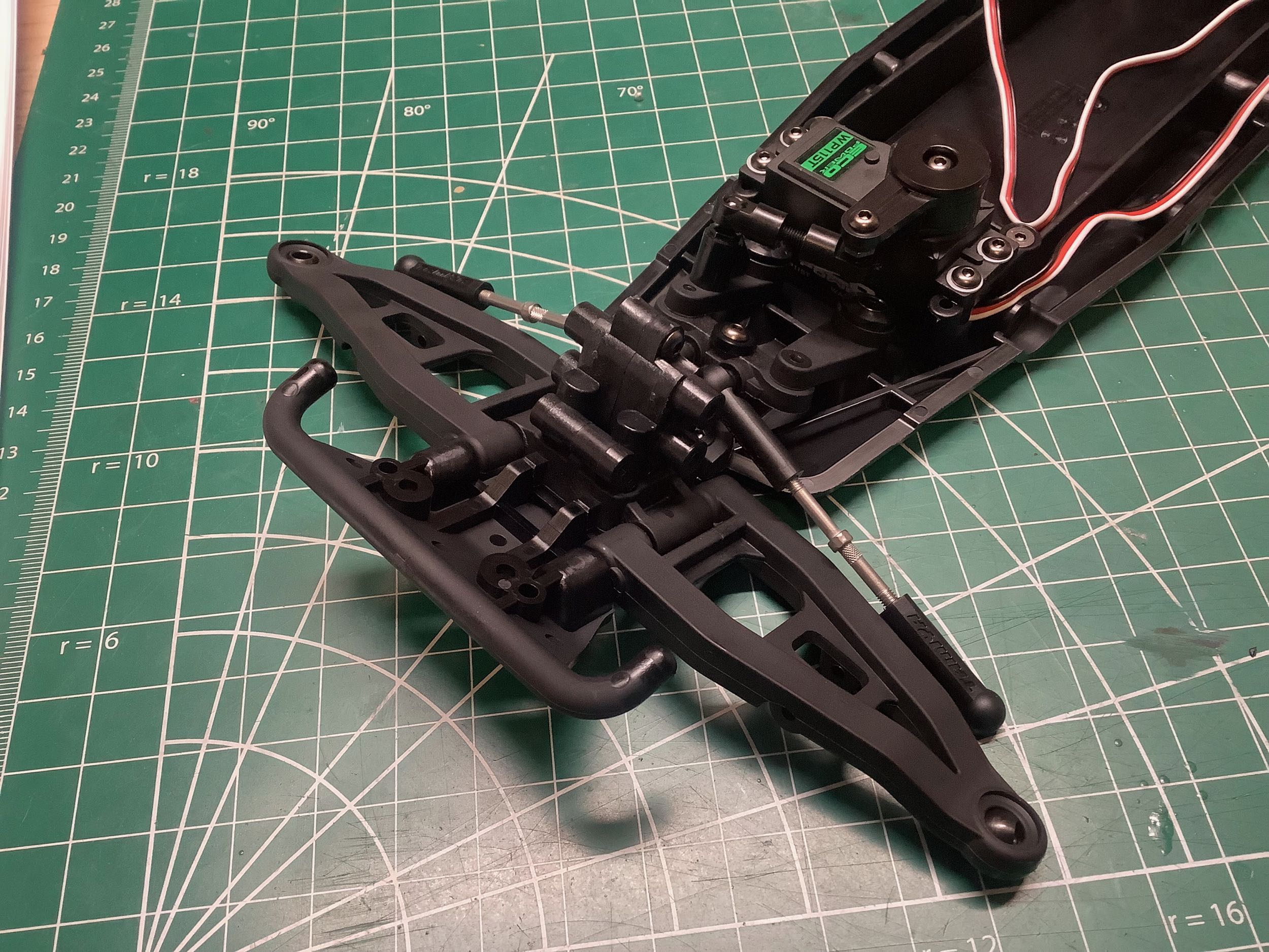
The four links shown on the left are the lateral supports for the rear
trailing arms. The link length is not intended to be
adjustable. On the right I've installed the link assembly onto the
chassis. The angled plate above the area is intended for the
speed controller.
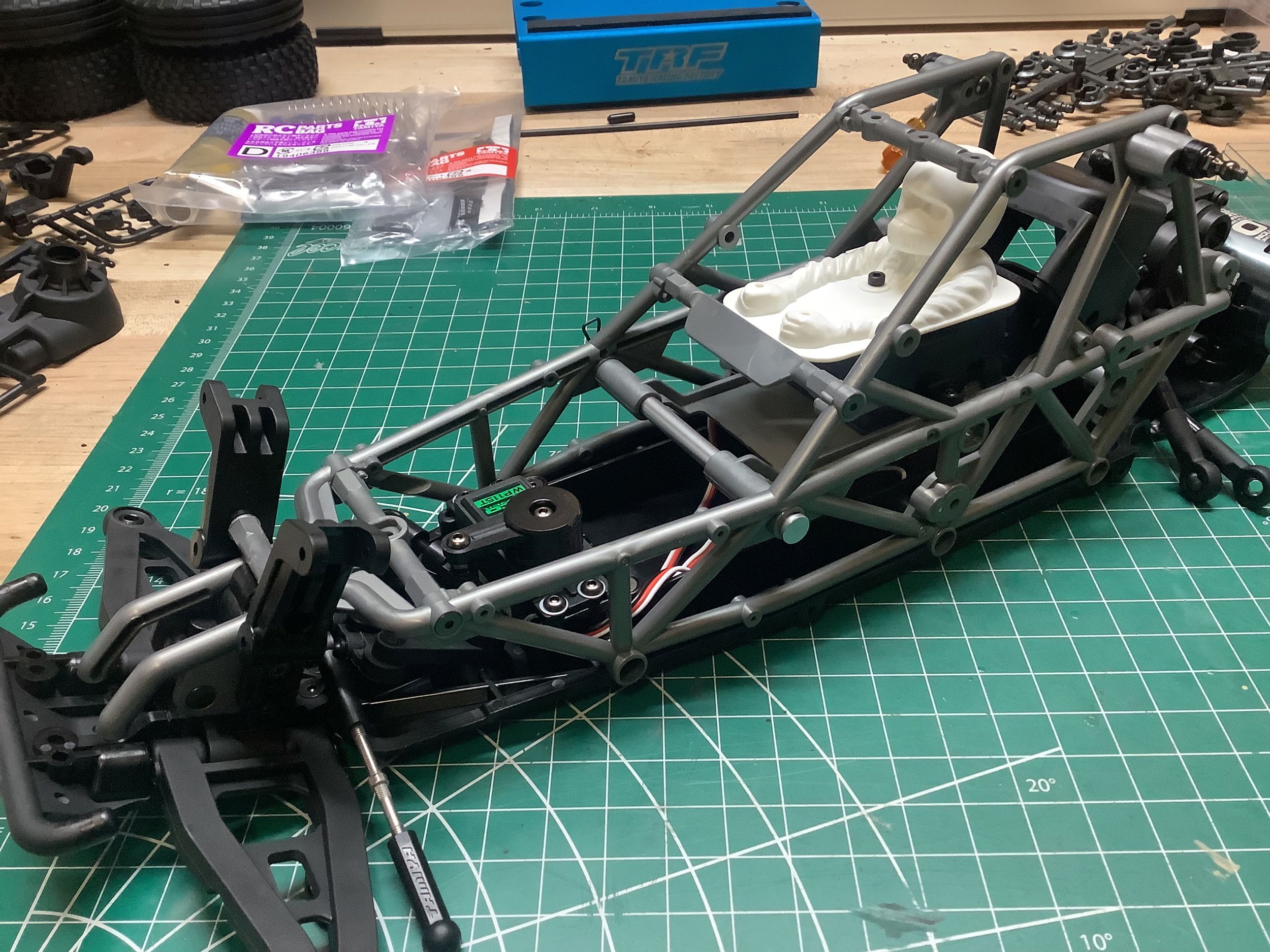
Hardware bag C is for the front suspension and the beginnings of the
roll cage. The right hand image shows the front roll cage which
spans to the front bumper and has numerous cross members. The
driver figure serves as a cover for the receiver. The battery
slips under the driver by removing the lateral aluminum locking bar
shown. The whole driver platform has to be tilted up to access the
battery.
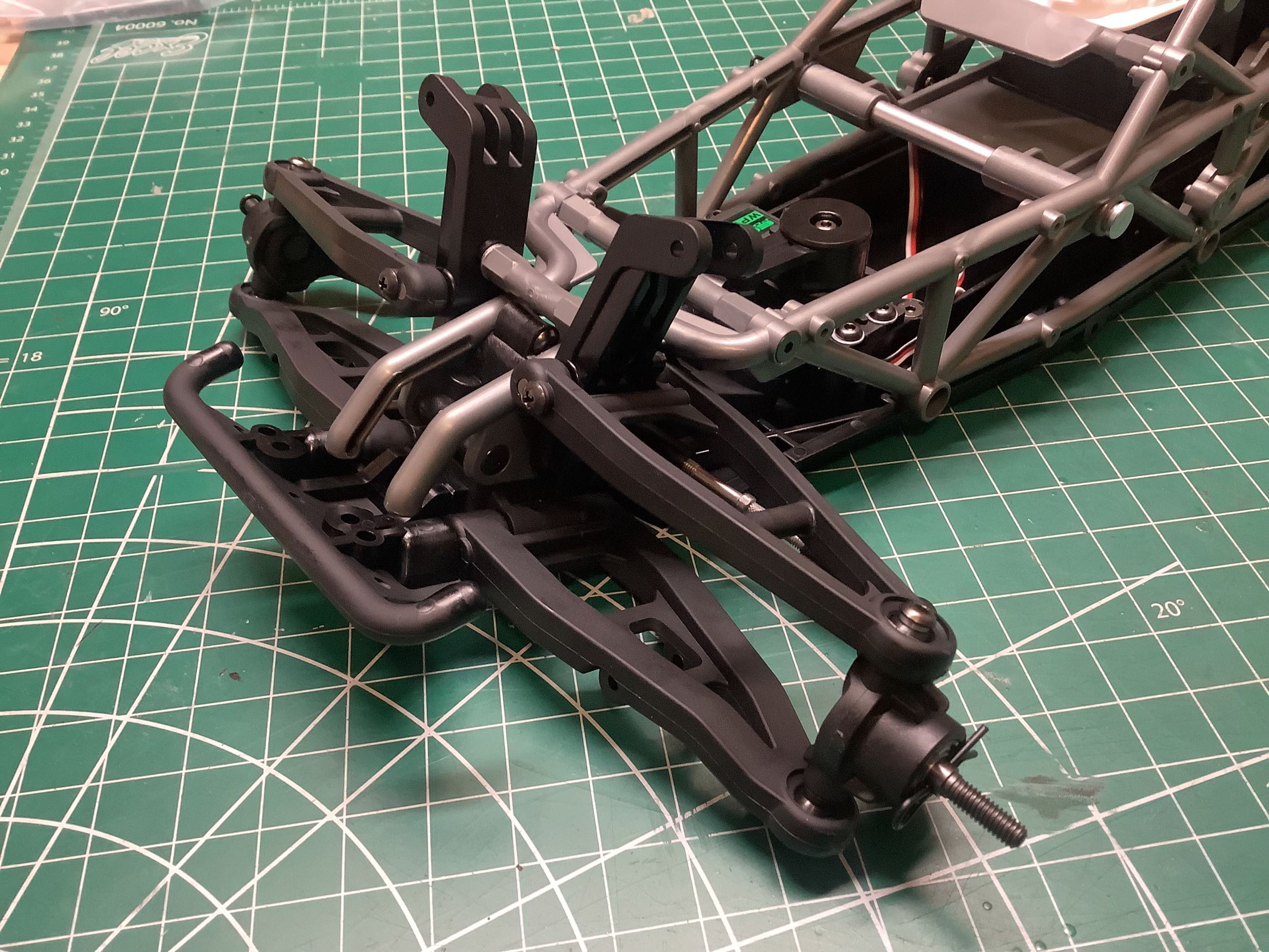
Here I've installed the front suspension. The upper and lower arms
are both wishbone type which provides excellent support. There
are ball joints in the end to support the steering knuckles. The
shock towers are separate plastic supports which are quite thick.
The front bumper is minimal and does not protect the suspension arms.
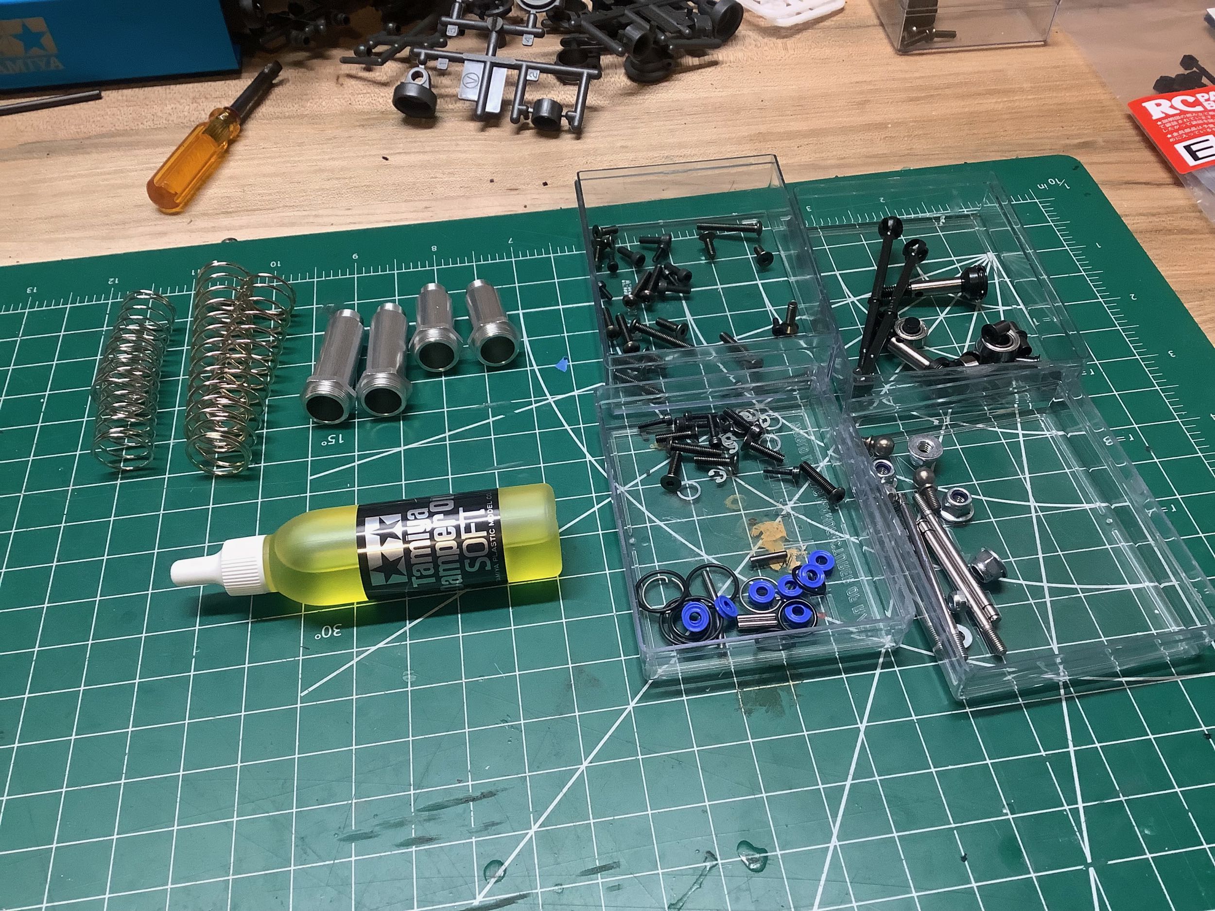
Hardware bag D is for the shocks and axles. The
shocks have aluminum bodies with plastic caps and rod ends. The
shock bodies are not threaded, so preload adjustment is done with a
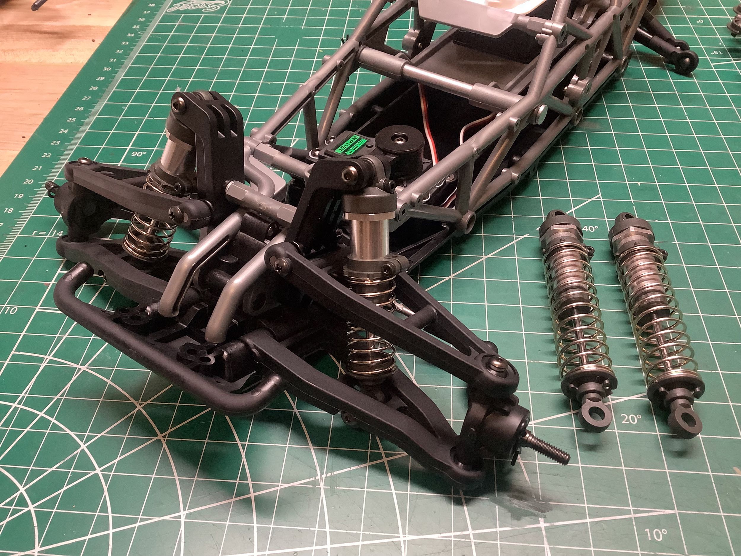
clamping collar. The front axles use quite a lot of preload as can
be seen in the picture on the right. The front shocks install
between the wishbone of the suspension arms which makes for a much
stronger installation than a typical cantilever.
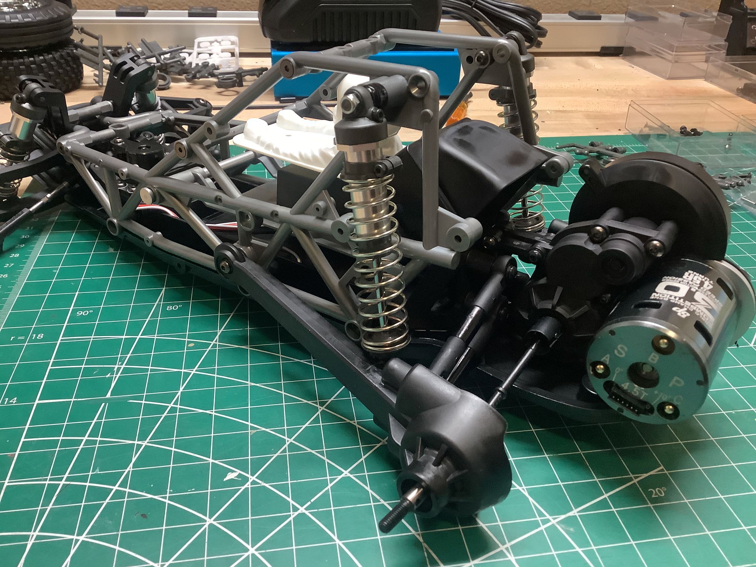
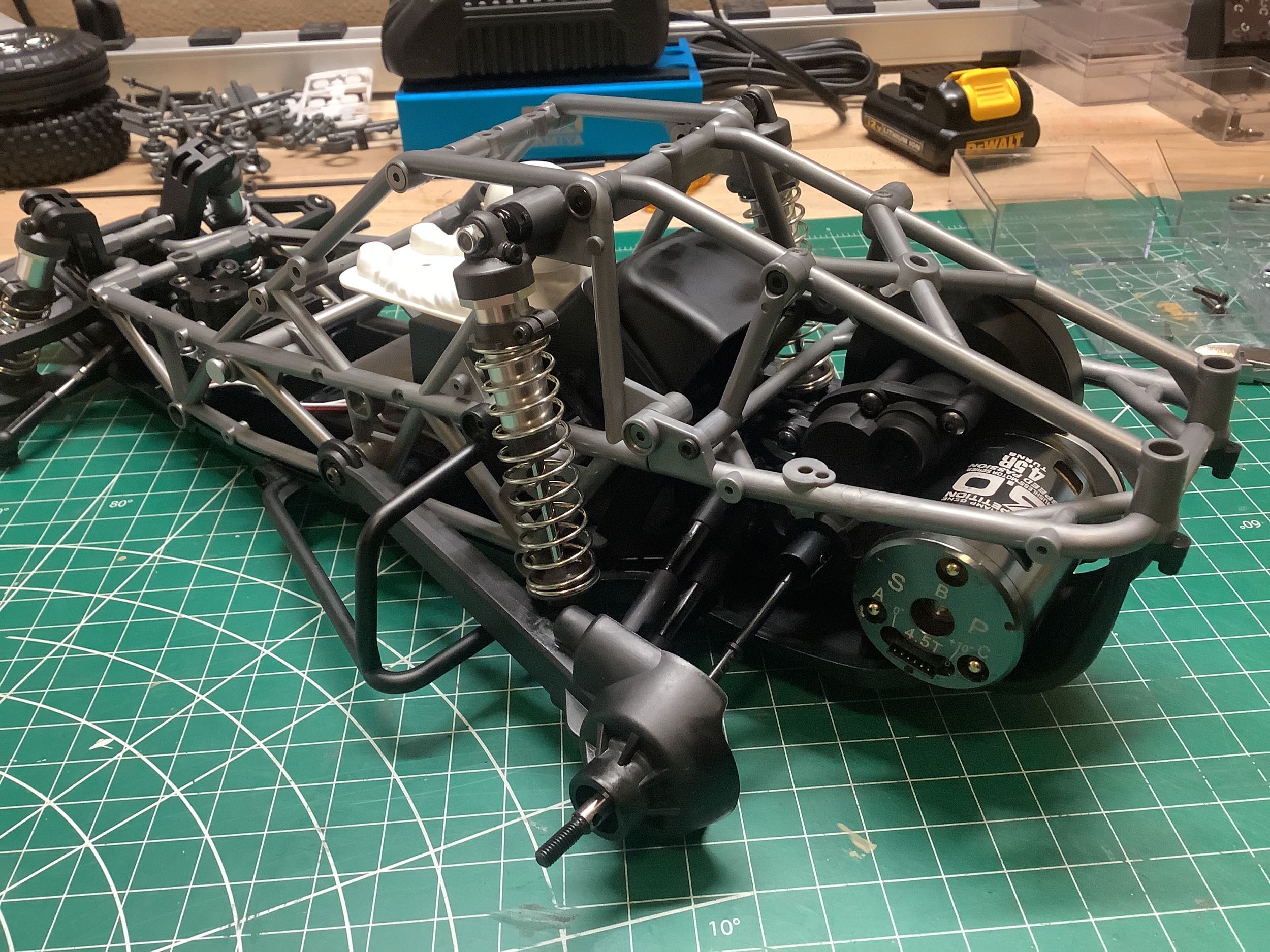
The rear shocks connect to the trailing arms which pivot off of a joint
in the roll cage. There is a nut trapped in the roll cage for
strength at this joint. The steel axles are CVD type at the outer
end and dog bones at the inner end. In the right hand photo I've
also installed the rear roll cage above the motor and gearbox, and the
side cages which protect the trailing arms in the event of a rollover.
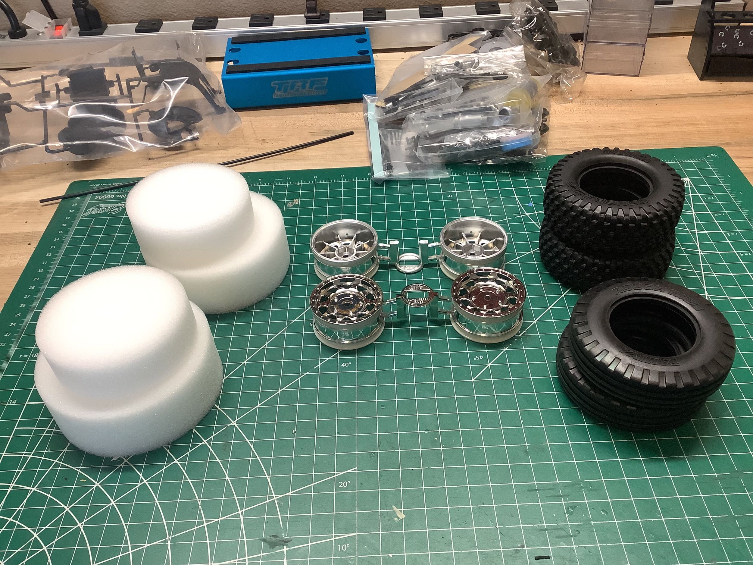
The tires and wheels are new and (so far) unique to
this vehicle. The wheels have a chrome finish and the tires have
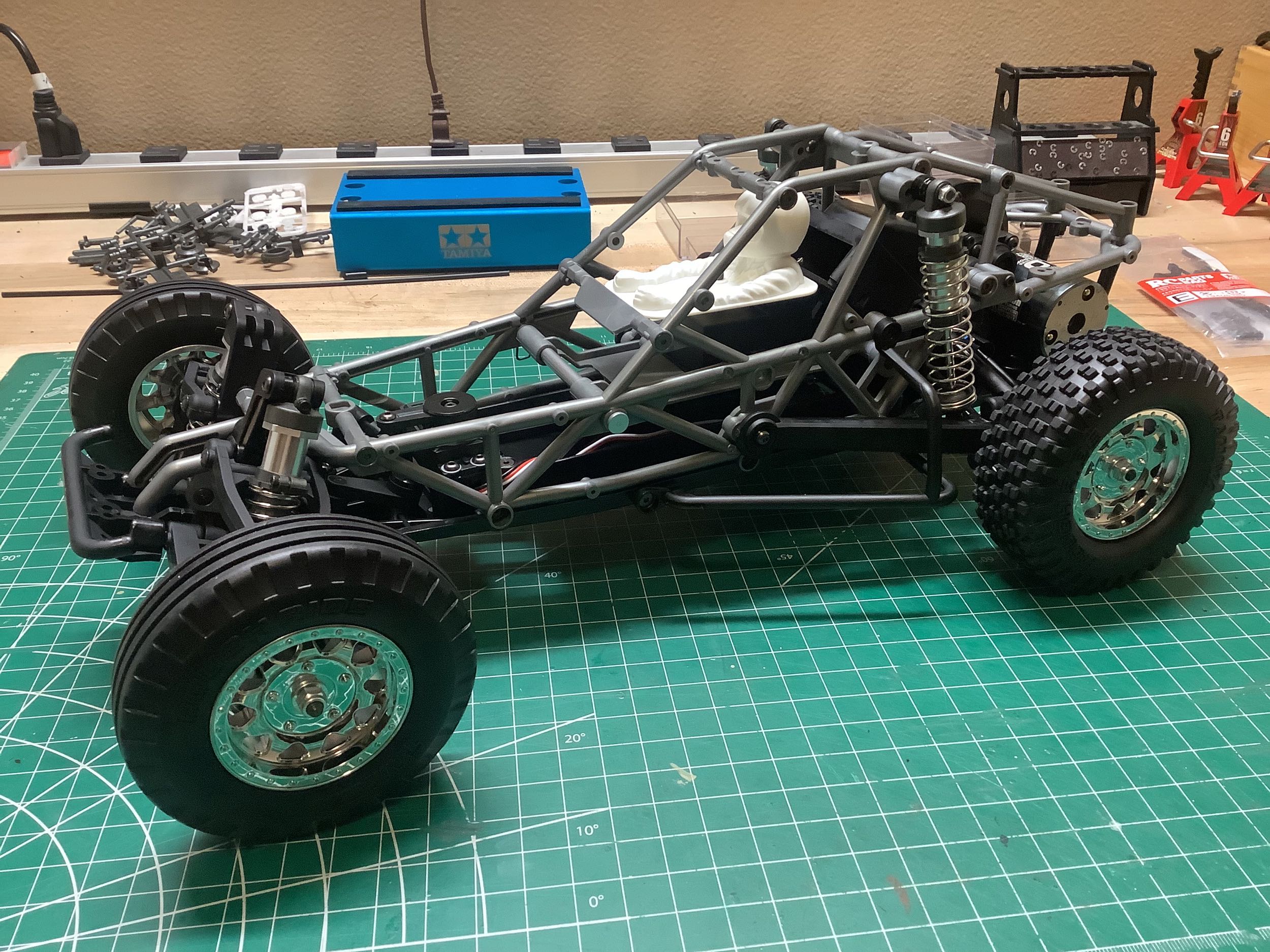
nice internal foams for support. The right hand photo shown the
completed rolling chassis. The buggy would actually look very good
just like this with no body at all.