Tamiya Avante Project
Page 1: Building the Frame
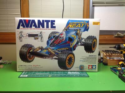
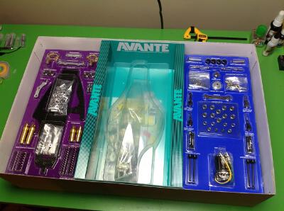
The Avante comes in a large, beautifully illustrated box. Inside
the contents are divided into three sections. On the left and
right are blister packs with some of the notable parts including the
carbon chassis plate, the gold anodized shock bodies, ball bearings,
special motor, and other metal parts. The center section has the
polycarbonate body and under tray. Beneath these are the plastic
part trees and hardware bags.
The assembly begins with the motor mount and rear gearbox.
This is not just your standard Mabuchi 540 motor, this is a custom
labelled, 25 turn, rebuildable brushed motor. It looks really
nice. We'll see if it has an increased performance proportional to
its looks. The model uses a 22 tooth aluminum pinion gear which I
immediately replaced with a Robinson Racing steel gear of the same
size. This is the only upgrade I made to the model.
Here's the beautiful carbon chassis plate with the motor and aft gearbox
housing attached to it. The use of a carbon chassis is the
biggest and most obvious change from the original model which used an
FRP (fiberglass) chassis.
The front gearbox housing comes next. At this point, only a single
bevel gear has been installed which rides on a floating axle. The
end of this axle protrudes and will connect to the center drive shaft.
The front gearbox is cantileverd off the front of the chassis
plate. At this stage in the build, the thin center is obviously
the weak point between the thick ends.
The front and rear differentials are internally identical but the front
has a longer housing. The model uses gear differentials, but not your
standard bevel gear
type. These are planetary differentials using only spur
gears. The first layer is an output
sun mating with 2 planets. The planet axles are locked to the
housing making it the planet carrier. The second layer is another
set of planets and the opposite side
sun gear. The two layers connect together with the planet gear
teeth which rotate in opposite directions. The sun gears are
splined to the axles. Note that
the diff ring gear is not a bevel, which means the 90 degree turn will
have to happen in another gear stage.
The rear differential drops into place from the bottom of the chassis
and is then enclosed with a cover plate. This makes access easy
for greasing, but you still need to pull the axles to actually remove
it. Note the super wide face width on the spur gears.
Now we do the same thing for the front differential. The
installation is similar to the rear except that the second stage is a
bevel set instead of a spur set. The axle supporting the idler
gear is inserted from the side and needs to be restrained with some tape
until a part holds it in later.
Step 10 begins the installation of the suspension arms much earlier
than the rest of the suspension. These are the rear lower arms
which need to be installed now because they will be locked by the
mid-plane chassis plate. In this case, the inside ball ends are
aluminum and the outside are plastic. The outer ends are not balls
but just sleeves. The thread between them is not a turnbuckle so
the length can only be adjusted by removing one end and this means you
need to get the lengths right now. A jam nut against the aluminum
end locks everything in place.
Unlike many 4WD buggies, this one actually has a center
differential. This is a ball differential which is integral to the
motor spur gear. This does not use a coil spring to adjust the
tightness, instead it uses a stack of 5 Belleville springs. The
right image shows the center diff installed in the rear gearbox, but at
this point there is still no gear to connect to the rear
differential. The center drive shaft is just a steel rod with the
ends flattened. It is not a hollow tube and it does not have any
splines.
The addition of another carbon plate at the mid-plane completely changes
the stiffness of the chassis. Now it is a brick. A really
light brick. This plate has plenty of cutouts to accommodate the
motor, the center drive shaft, and the later installation of
wires.
Time to finish the rear gearbox. One more idler gear completes the
rather complex path to the rear axle. There is the pinion:spur
stage, a bevel stage, 2 spur stages, and then the differential.
Since the rear has one more stage than the front, you'd think this would
result in them rotating opposite directions. I was actually a bit
worried about this until I saw that they mirrored the direction of the
bevel gears to compensate.
Now we can close out the rear gearbox from above and also install the
shock tower and rear bumper. The shock tower is also a carbon
plate. You can also see the fine wire sway bar clipped to the
chassis.
©2017 Eric Albrecht

