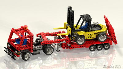
Features
|
|
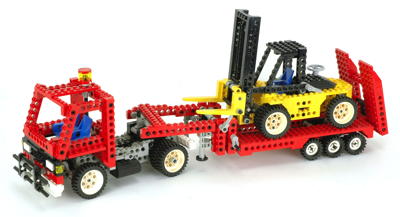
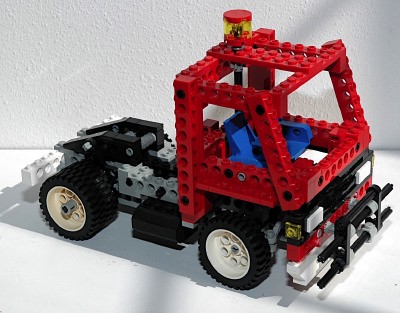
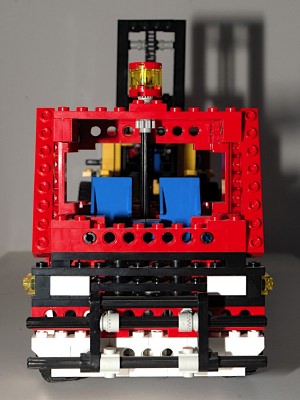
Tractor
The tractor is a single rear axle unit with dual wheels and
tires. It's a bit boxy but does a great job of integrating with
the set of while using minimal parts.
|
|
|
Steering
The front wheels can be steered using an overhead "hand of god" control. The overhead control drives
an axle connected to
a pair of 14 tooth bevel gears.
The second axle drives a flexible rack via an 8
tooth pinion
gear. The steering mechanism itself uses the steering arms
and toothed links as shown in the computer image.
Note that, in this case, the steering arms actually point forward
instead of back. This works OK with these control arms because
there is no caster (the wheel axle is centered under the rotation
point). If there were caster, this would be an unstable
arrangement since the reverse caster will cause the wheels to diverge
from center when moving forward rather than return.
|
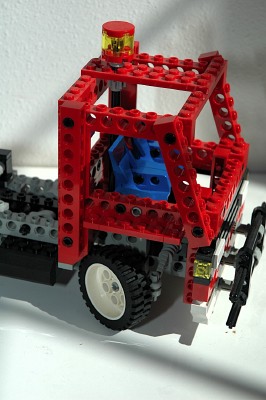
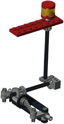
Ldraw file courtesy of Benjamin Wendl.
Click for an animation of the
steering in motion.
|
|
Fifth Wheel
Coupling
The 5th wheel coupler works very much like a real tractor. The
coupling hitch on the trailer slides in between the side rails as the
tractor backs up to it. After the pin contacts the forward stop,
the unit is locked.
This coupler is locked via a crank on the left side. The pole
reverser handle turns an axle attached to a pair of crankshaft
elements. These pull a link which is attached to a pair of
triangles. When these triangles are pulled forward, they engage
the trailer pin. Since the crankshaft elements go over center,
this locks the pin in position so that towing force cannot pull it
open. This effect can be seen in the animation.
|
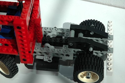
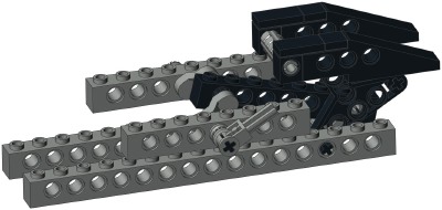
Ldraw file courtesy of Benjamin Wendl.
Click for an animation of the
coupling engaging. |
|
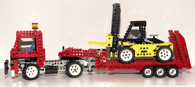
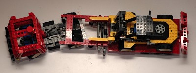
Trailer
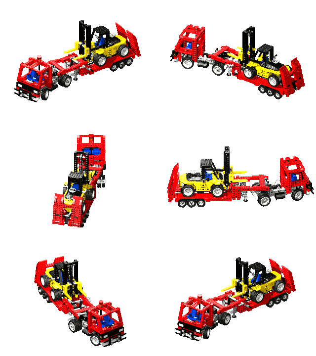
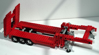
This low frame multi-axle trailer is obviously designed for hauling
heavy equipment. It has an open frame and a sturdy loading ramp.
|
 |
|
Landing Gear
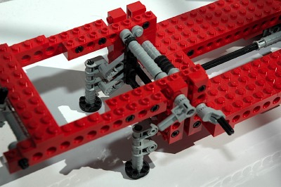
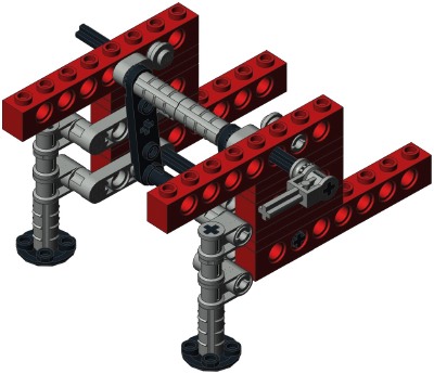
The "landing gear" is the pair of feet which deploy to support the
front of the trailer when not attached to a tractor. They raise
and lower on a 4-bar linkage, keeping them perpendicular to the
ground. A pole reverser handle turns an axle attached to a pair
of crankshaft elements. These drive a link which moves the 4-bar
linkage. Since the crankshaft elements go over center, this locks
the feet in the down position so they do not collapse under
weight. In the photograph you can see that these parts are
stopped against a pair of 1x1 round plates which prevent further
rotation. |
Ldraw file courtesy of Benjamin Wendl.
Click for an animation of the
landing gear deploying. |
|
Loading Ramp
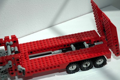
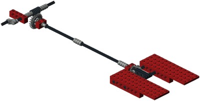
The large rear loading ramp is driven by a crank on the front
side. This crank turns a worm gear which mates with a 24 tooth
crown. An axle runs the whole length of the trailer and then
drives a perpendicular axle through a set of 14 tooth bevel
gears. This final axle drives a pair of liftarms which raise and
lower the ramp.
Because the mechanism uses a worm gear, it cannot be backdriven
(because the axial friction is higher than the
backdriving torque due to the screw pitch angle). This
helps keep the ramp up when in transit.
|
Ldraw file courtesy of Benjamin Wendl.
Click for an animation of the
loading ramp
in motion. |
|
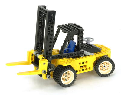
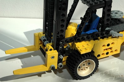
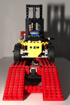
Forklift
If we are to assume that the forklift is to scale with the rest of the
set, then this is a huge forklift indeed. It would be perhaps 30
feet
long. There are forklifts this big which would typically be used
for
heavy loading of things like shipping containers. The double
front tires suggest that this is designed for very heavy lifting.
The train roof used as an engine cover is a nice touch.
|
|
|
Steering
The rear wheels can be steered using an overhead "hand of god" control
behind the cabin. The
wheel control drives
an axle connected to
a pair of 14 tooth bevel gears.
The second axle drives a rack via an 8
tooth pinion
gear. The steering mechanism itself uses the steering arms
and toothed links as shown in the computer image. |
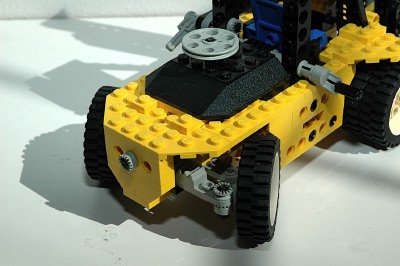
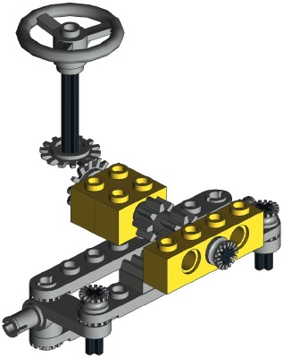
Ldraw file courtesy of Benjamin Wendl.
Click for an animation of the steering
in
motion.
|
|
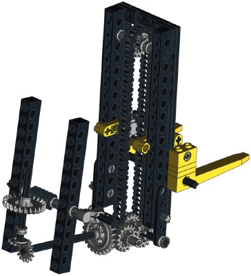
Lift
The forks are lifted via a fairly complex gear train. A crank on
the right side turns a worm gear. The presence of the worm gear
ensures that no weight on the forks will backdrive the system.
Next is a 24 tooth crown followed by a pair of 14 tooth bevel
gears. Then there's another gear pair with a 24 tooth crown and a
16 tooth spur. This drives yet another 16 tooth spur. It is
important to note that this second spur gear is on the same axle about
which the whole fork assembly tilts. This allows torque to be
passed through this joint no matter what position the tilt is in.
A final pair of 16 tooth spur gears are located at the top and bottom
of the fork boom. They are connected by a long chain loop.
A single chain link is the wide (tread) variety. This connects to
the fork assembly and forces it to follow the chain movement.
The fork assembly is one of the least binding of the Technic
forklifts. A series of tiles along the front of the boom keep the
forks from tipping into the boom, and the flanges on a pair of liftarms
keep the forks from tipping away. The semi-round nature of the
liftarms keep everything moving smoothly as it slides along the boom.
|
|
|
Tilt
The forks can be tilted via a pole reverser handle on the left
side. This handle drives a crankshaft element connected to a
link. The link tips the whole boom assembly about the lower pivot
axle.
Since the crankshaft element goes over center, this locks the boom in
the transport position so the lift weight will not cause the boom to
tip forward.
|
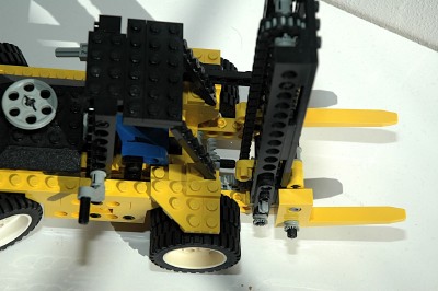
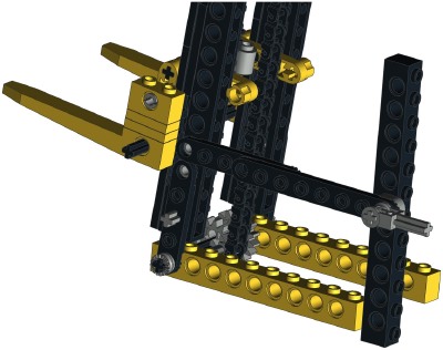
Ldraw file courtesy of Benjamin Wendl.
Click
for an animation of the forks tilting. |
|
Wheels and Tires
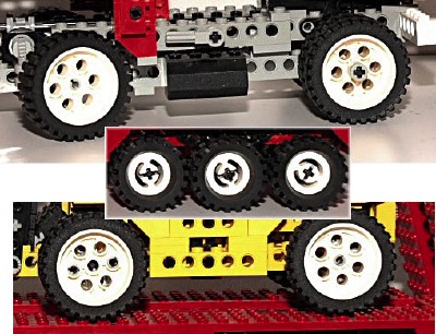
This set is a gold mine of wheels and tires.
The tractor and the forklift each have 6 of the Model Team wheels and
tires, for a total of 12.
The trailer has 6 of the old style small wheels with the medium size
tires.
|
|

