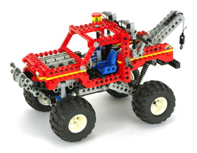
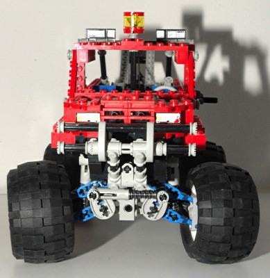
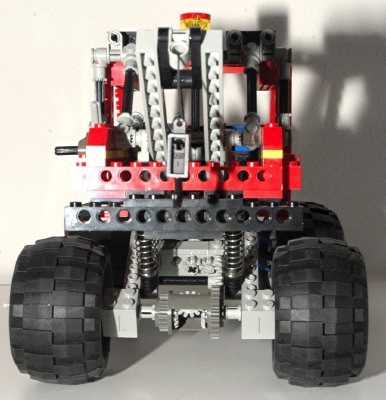
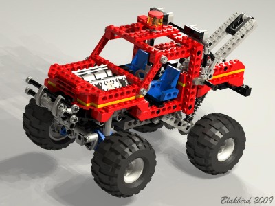
Features
|
|
Steering
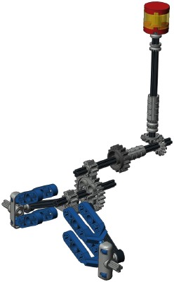
The front wheels can be steered using an overhead "hand of god"
control. This wheel turns a set of 14 tooth bevel gears.
The next axle passes through one of the new 16 tooth idler gears (shown
in dark gray) before meeting a set of 8 and 24 tooth spur gears.
Finally, an 8 tooth pinion mates with the tiny new gear rack.
This gear rack has ball joints at either end which attach to steering
links. Thes links terminate at the ball joints on the steering
control arms.
Because everything in the system uses ball joints, the steering is able
to function even when the geometry changes due to suspension travel.
The steering wheel at the driver's position is not connected to
anything.
|
Click for an animation
of the
steering
in
motion.
|
|
Drive Train
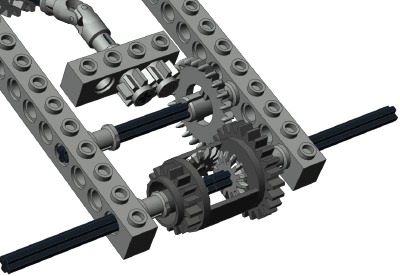
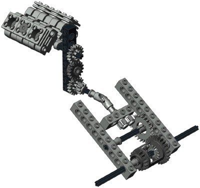
The engine is connected to the rear axle via a fairly convoluted gear
system made even more complex by the presence of the rear suspension.
The crankshaft turns a 16 tooth gear which mates with a 16 tooth idler
followed by another 16 tooth spur. The second gear passes engine
torque through, and is the same gear which is located in the steering
system described above used as a mere idler. The next gear is an
8 tooth spur but this acts only as a spacer; it is not attached to
anything.
The location of the universal joint is very important. Since the
rest of the system is attached to the movable trailing arm of the rear
suspension, the drive system must be able to pivot about the same axis
as the suspension. The u-joint allows this.
Next, a pair of 8 tooth pinions move the torque to the right into a 24
tooth crown, the first time the gear ratio has changed. This
crown mates with the ring gear of the differential, resulting in a
total ratio from the engine of (16:16 x 16x16 x 8:8 x 8:24 x 24x24) =
1:3.
|
|
|
Engine
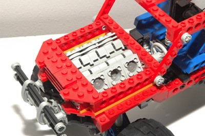
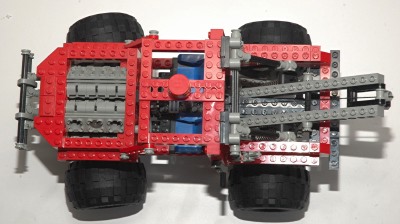
The rear wheels are used to drive a V-6 engine.
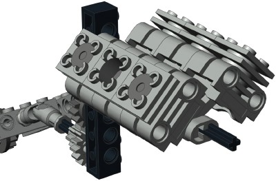
The engine is made from cylindrical engine elements. The two
cylinder banks have a standard V angle of 90 degrees. The
crankshaft is
offset 1/2 stud from center, giving the pistons a stroke of 1
stud. Each pair of pistons shares a common crank pin.
Because the crank pins are each offset 180 degrees, the forward and
back cylinders are synchronized. This can be seen clearly in the
animation.
This engine bay certainly is packed with engine. I suspect this
truck has a very high power to weight ratio. You can see the
massive torque of the engine twisting the frame in the animation!
|
|
|
Differential
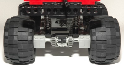
The rear axle is "live" and use a differential
gear which incorporates a built in 24 tooth ring gear (new this
year). The differential is made
to house 3 of the 14 tooth bevel gears. One is on each axle,
and one planet gear in the middle allows the axles to turn at different
rates. |
|
|
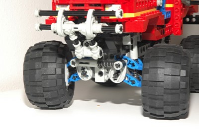
Front Suspension
This is some sweet front suspension, unparalleled in any other Technic
set.
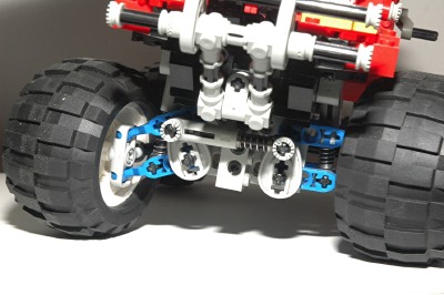
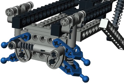
Suspension motion is controlled by a double wishbone system on either
side which uses the new A-arms, shown in blue. The ball joints at
the upper and lower A-arms connect to a control arm with ball joint
sockets. This system results in a 4 bar linkage which keep the
wheels perpendicular to the ground as the suspension moves through its
travel.
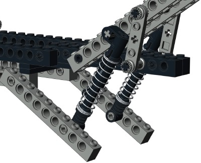
Attached to the lower A-arms are a pair of shock absorbers anchored to
the frame. This allows the suspension on either side to operate
independently. The suspension has significant travel, limited
only by the bottoming of the shock absorbers. You can see from
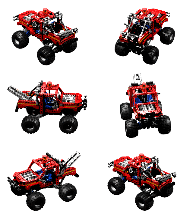
the computer image that significant thought was put into the attach
point of the shocks. The upper end is offset by half a stud using
engine crankshaft elements.
Finally, there is a third shock absorber which acts as an anti-sway
bar. This is attached to a pair of cams and links the right and
left side wishbones to each other. The result of this is that some
of the force from a leaning vehicle is transferred to the other
side. This system also results in a stiffer spring rate when both
sides move together than when they move independently.
|
Click for an animation
of
the suspension
in
motion. |
|
Rear Suspension
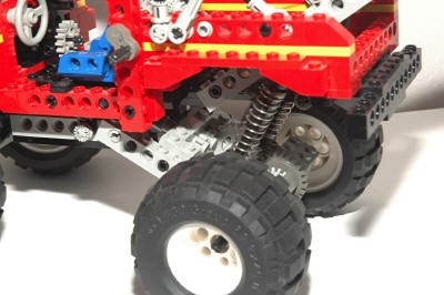
The rear wheels are supported by a pair of trailing swing arms with the
large size shock absorbers. Though this makes the suspension
itself independent, the live rear axle with a differential effectively
links the two sides together. You would need u-joints on either
side of the diff to make this truly independent.
|
|
|
Winch
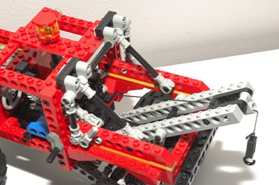
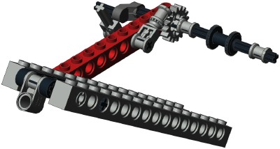
There is a rear boom which rests at a fixed angle using several
liftarms. A ratcheting winch is controlled by a crank (literally)
on the left side of the vehicle. A pole reverser handle with a
bushing on it acts as a pawl, mating with a 16 tooth gear used as a
ratchet plate. Another pole reverser handle releases the
mechanism.
|
|
|
Wheels and Tires
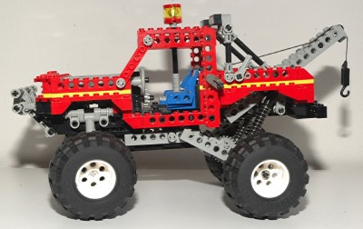
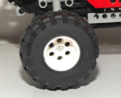
This set uses 4 of the new large 68.8x40 balloon tires and white wheels.
|
|

