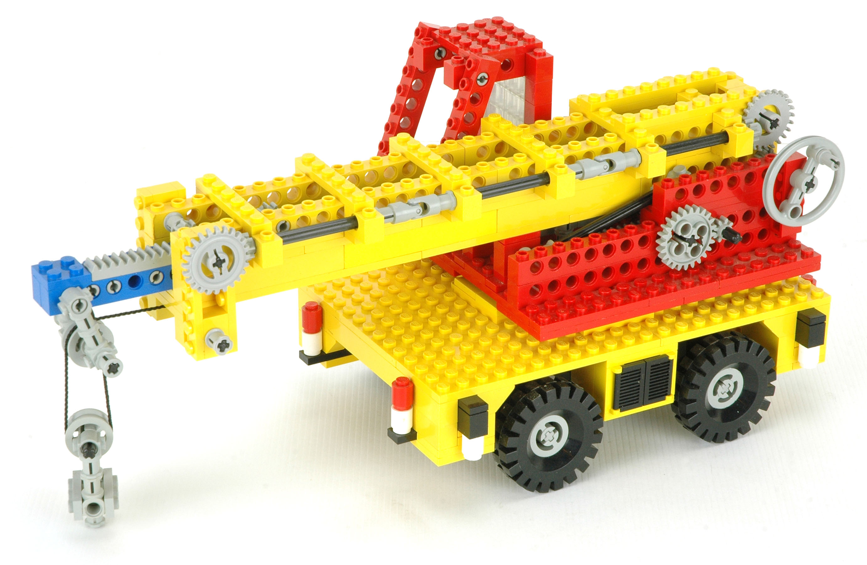
Features
|
|
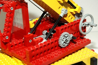
Luffing Boom
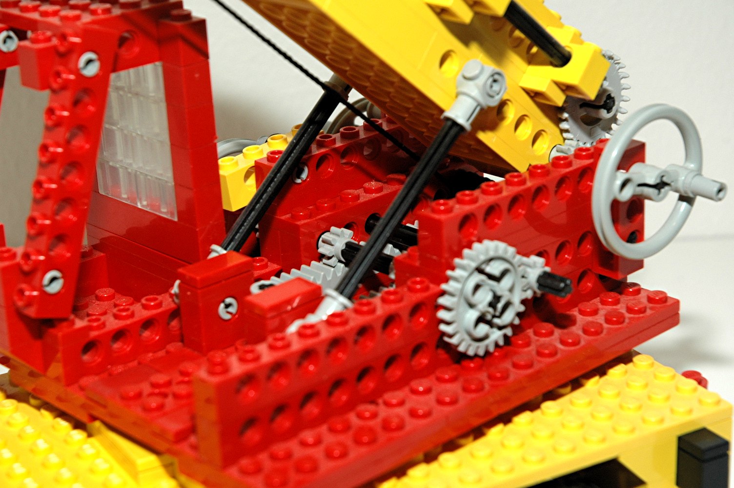
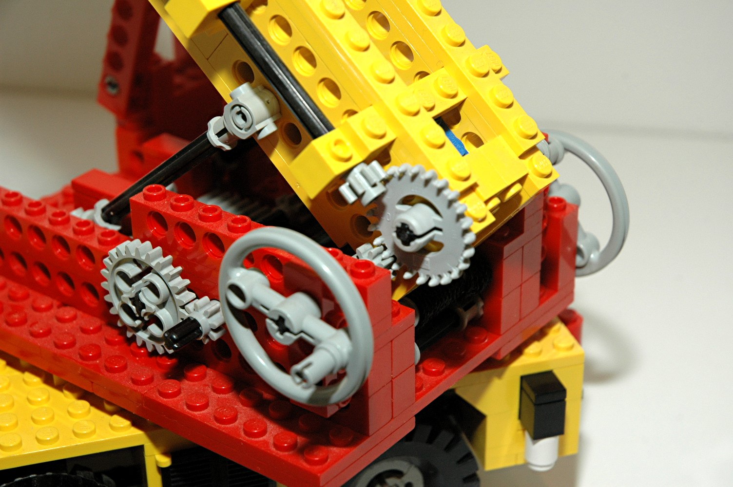
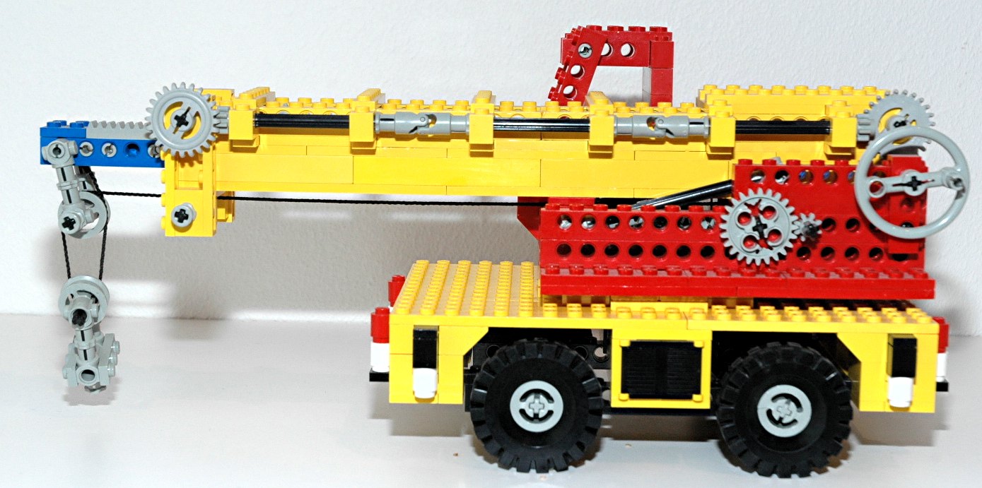
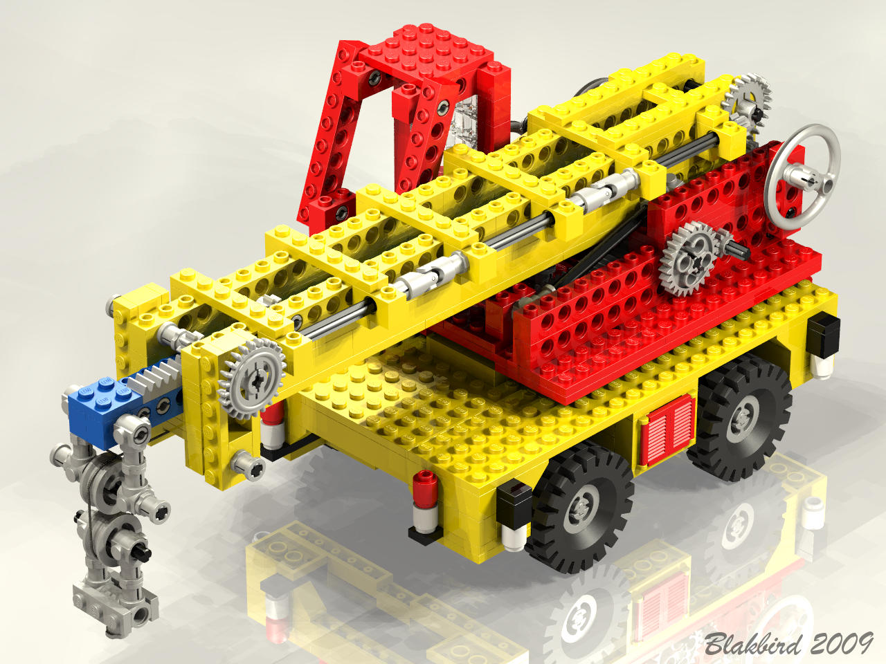
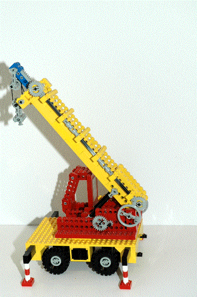
The boom can be rotated from a position parallel to the ground up to an
angle of about 50°. This rotational motion is actually
accomplished via a translating rack and some push rods. The boom
angle is maintained by a ratchet and pawl system.
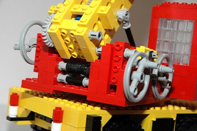
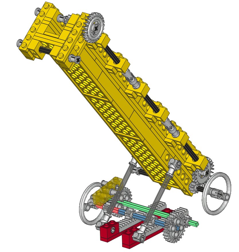
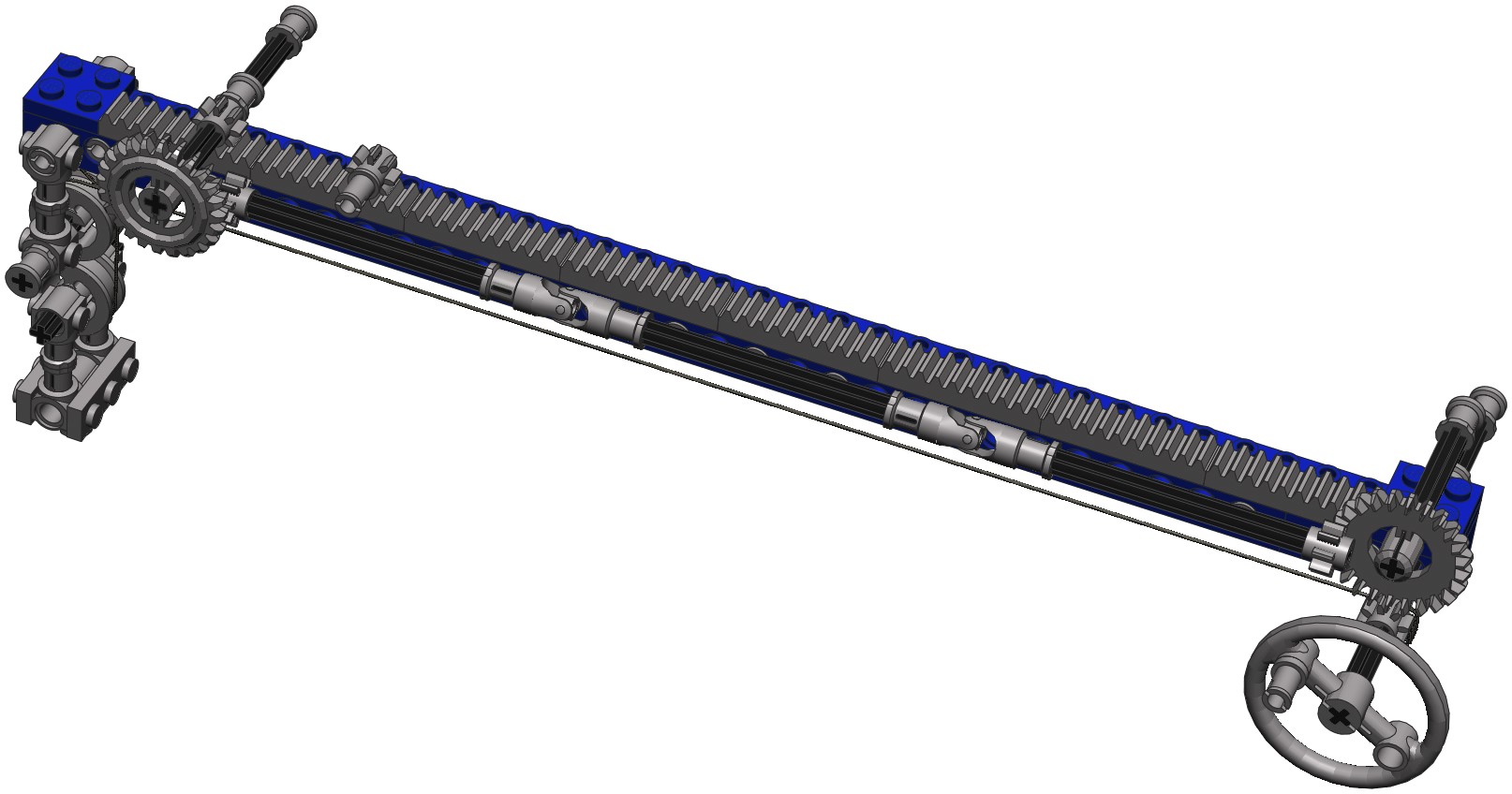
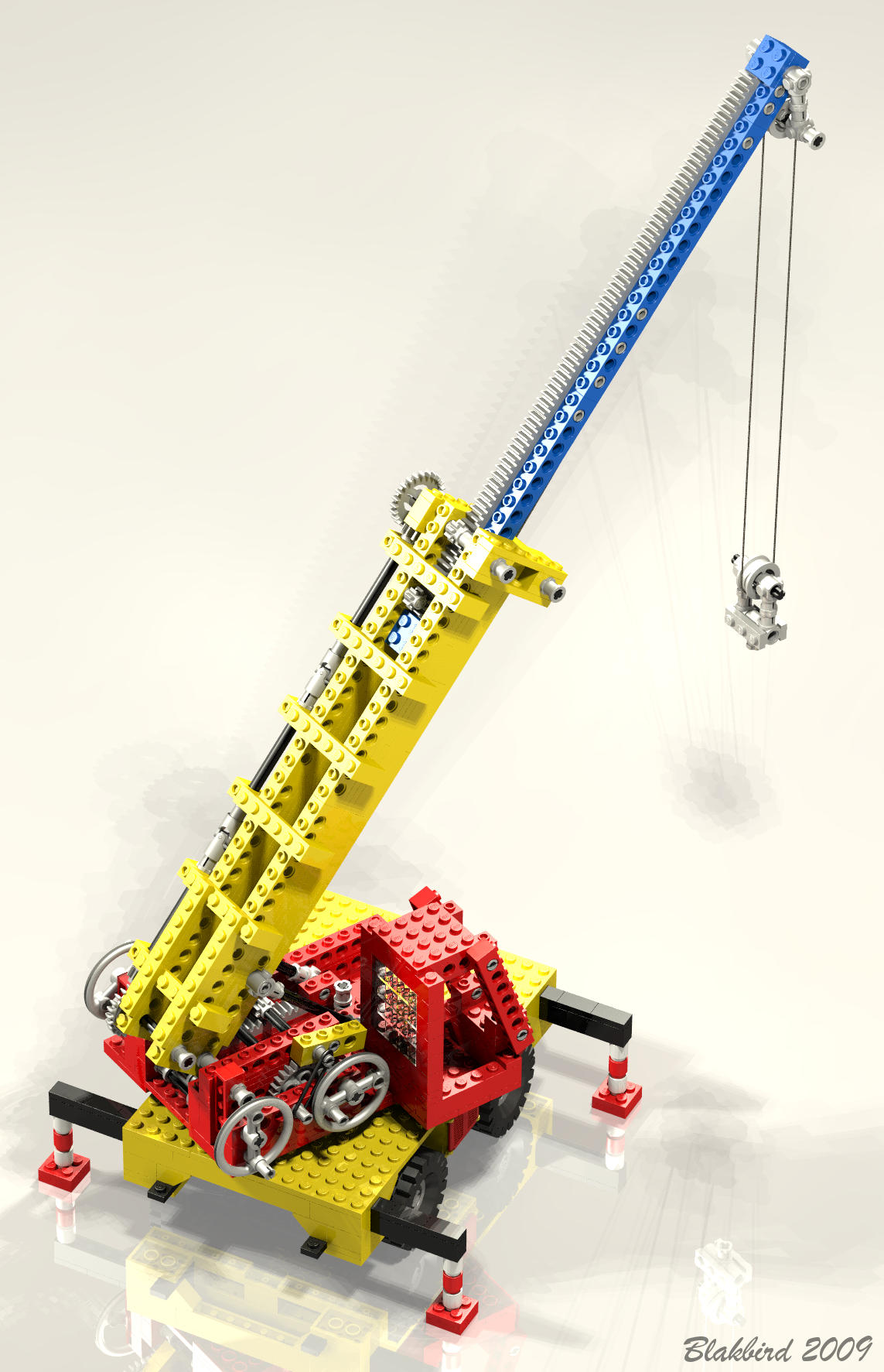
The computer image at the right has been color coded to make the
mechanics easier to understand. The boom itself pivots on an axle
(the black horizontal axle). A crank drives an 8 tooth gear (red
axle), which in turn drives a 24 tooth gear. A second parallel
axle (green) crosses the mechanism and drives another pair of 8 and 24
tooth gears for a total gear reduction of 9:1. The final axle
(blue) passes over a set of gear racks and drives them with a pair of 8
tooth pinions. The gear racks are part of a translating
rack assembly. A pair of push rods connect the rack assembly to
the boom. As the rack is translated aft, the push rods drive the
boom up. At the beginning of motion, the mechanical advantage is
quite poor because the push rods are almost parallel to the boom.
For this reason, a lot of force is required at the crank to get things
moving. Once the boom has been raised about 15 degrees, the crank
turns easily. Note that a boom rest was added in later versions
of this model to prevent the boom from going all the way down.1
The 24 tooth gear directly behind the crank (on the green axle) which
acts as a ratchet. A rubber band pulls a 1x4 beam used as a pawl
down onto the gear. This beam effectively locks rotation in one
direction, but allows it in the other direction. So as the crank
is rotated, the pawl skips over the gear teeth, but when the crank is
released, the ratchet cannot turn backward. The pawl must be
manually lifted off of the ratchet to lower the boom.
|

Click for an animation of the boom
luffing.
|
|
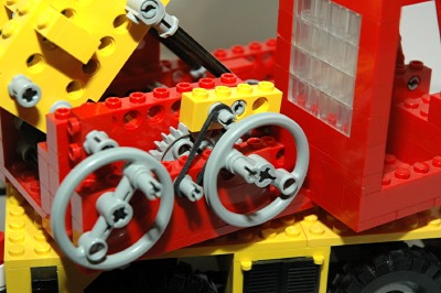
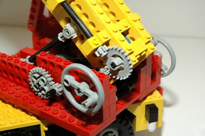
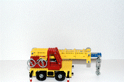
Telescoping Boom
The boom can telescope to approximately 180% of its original length. A
smaller inner boom, constructed of plates and covered with rack gears,
is nested inside the main yellow boom, constructed of bricks layered
with tiles. A crank on the left side drives a long axle parallel
to the boom via a triplet of two 8 tooth pinions and a 24 tooth crown
gear. This axle runs the entire length of the boom, spliced at
two points with u-joints. At the upper end of the boom, the
rotation is turned 90 degrees through another set of gears. The
cross axle contains an 8 tooth pinion which translates the entire inner
boom axially.
There are stops at either end of the inner boom to prevent it from
extending or retracting too far. The cantilever moment of the
inner boom is carried by a force couple. The end of the inner
boom is prevented from moving down by contact with the main boom, and
is prevented from moving up by a second pinion gear supported by an
axle pin.
As can be seen in the animation, the sheave is effectively raised by
the telescoping of the boom. Since the length of the boom has
increased, less cable is available in the vertical direction.
|

Click for an animation of the boom
telescopic motion.
|
|
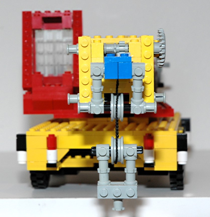
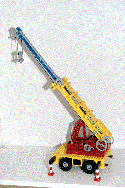
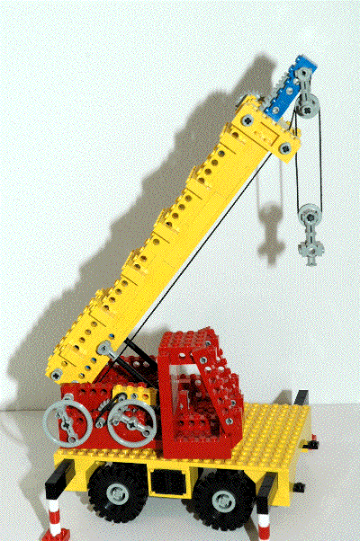
Hoist
A hoist is available which uses the new LEGO® string to
lift a sheave. A pulley wheel is used as a crank, and directly
rotates an axle to which the string is tied. This axle acts as a
winding drum and raises and lowers the sheave.
Because the string is simply tied to the axle, it tends to just slip
when the cable is fully payed out. A certain amount of the cable
needs be manually wound around the axle before it works properly.
|
Click for an animation of the hoist in
motion.
|
|
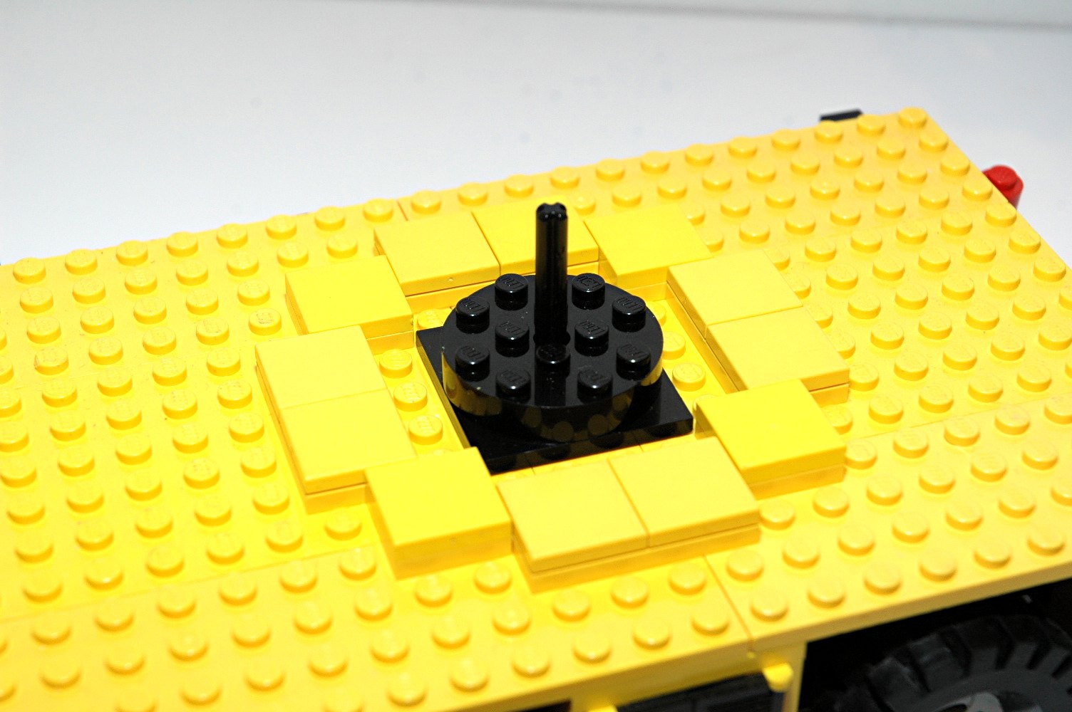
Slewing
The 360 degree rotation of the boom and cab is accomplished very
simply. An old 4x4 turntable is used, surrounded by a series of
tiles for extra overturning support. An axle runs up the center
of the turntable and is fastened above and below by bushings to help
keep the upper assembly from falling off the turntable. Actual
rotation is accomplished manually; there is no drive system for slewing.
|
|
|
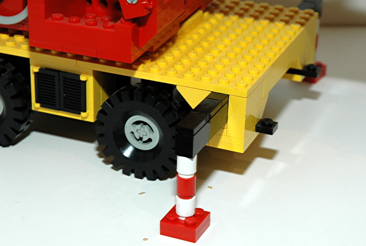
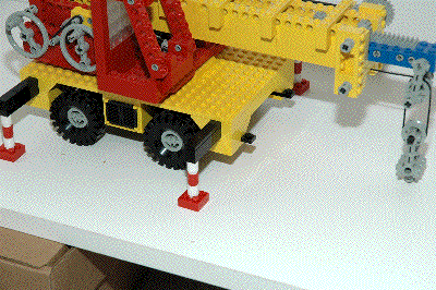
Outriggers
Preparing the outriggers on this model is rather labor intensive.
First, 1x8 bricks covered with tiles extend from the main body. A
1x1 plate on the bottom inboard corner prevents the outrigger from
extending too far and falling out. Next, a pair of 1x1 cylinders
are attached to the existing cylinder which is already stored at the
outboard end of the outrigger. Finally, a pad consisting of a
pair of 2x2 plates is extracted from a compartment in the side of the
base and attached to the cylinders. All of this must be
accomplished manually for each outrigger.
Despite the difficulty in deploying them, the outriggers work quite
well. They provide a wide base for stability and are very
slightly taller than the tires so that the tires are lifted off of the
ground. Because there are four outriggers and because the feet
must be parallel to the body, they only work on perfectly level ground.
|

Click for an animation of the
outrigger
in motion.
|
|
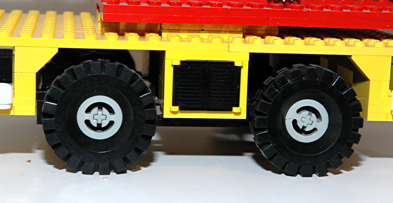
Wheels and Tires
This set uses four rubber 17x43 tires and standard old gray
wheels. The wheels are supported by the new axle pins.
|

|


