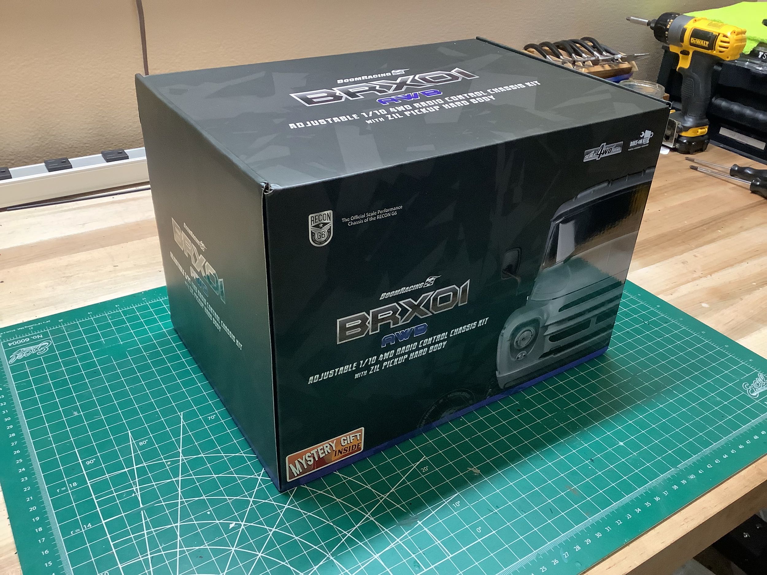
This is not the style of RC box I am used to. This tall, almost
cubic box contains the combination of the adjustable wheelbase chassis
and hard body kit. On the left in the lower corner, you can see a
sticker which indicates there a "mystery gift" inside. Wonder what
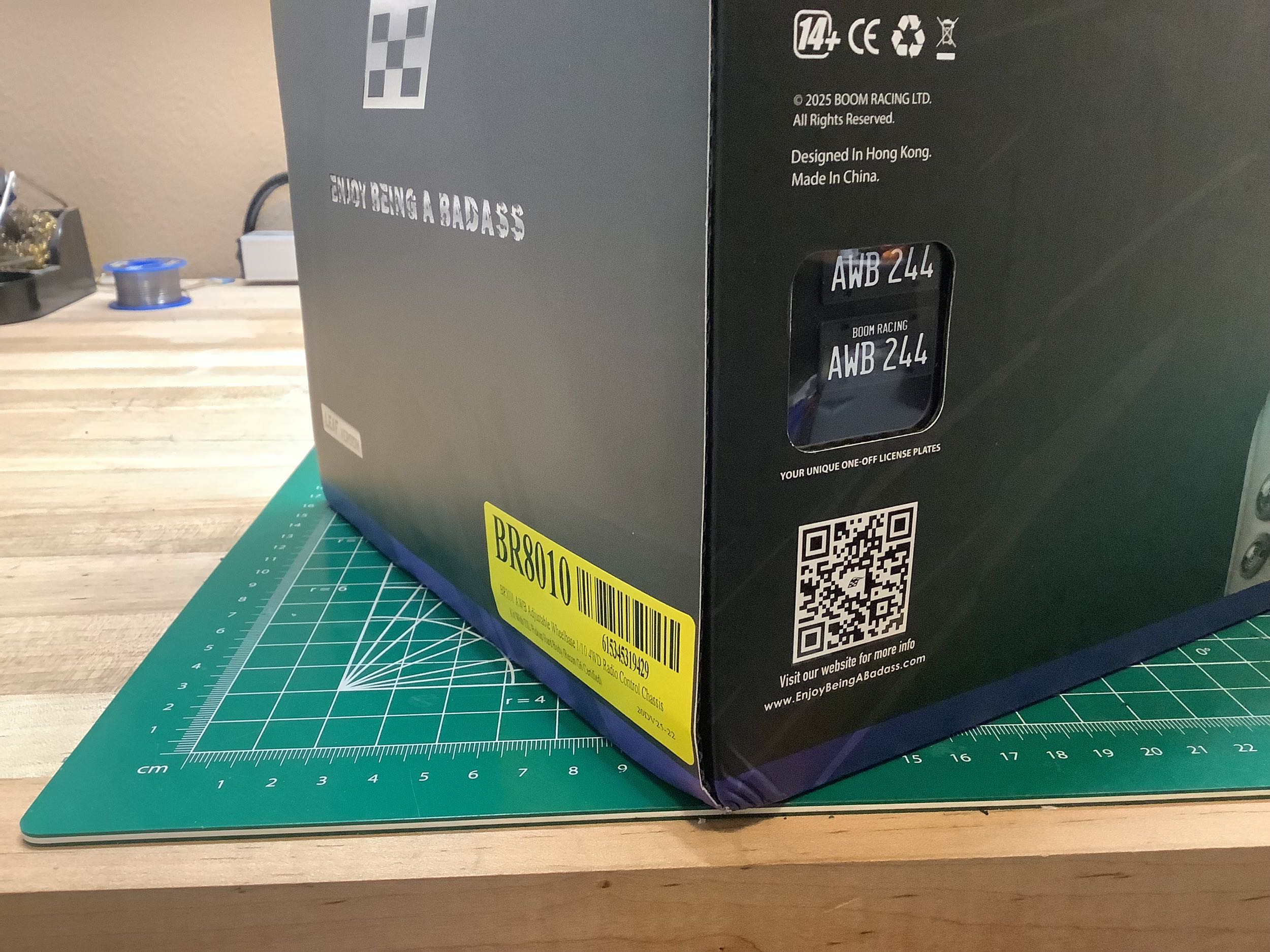
it is? On the right, you can see that there is also a unique
license plate which effectively acts as a serial number.
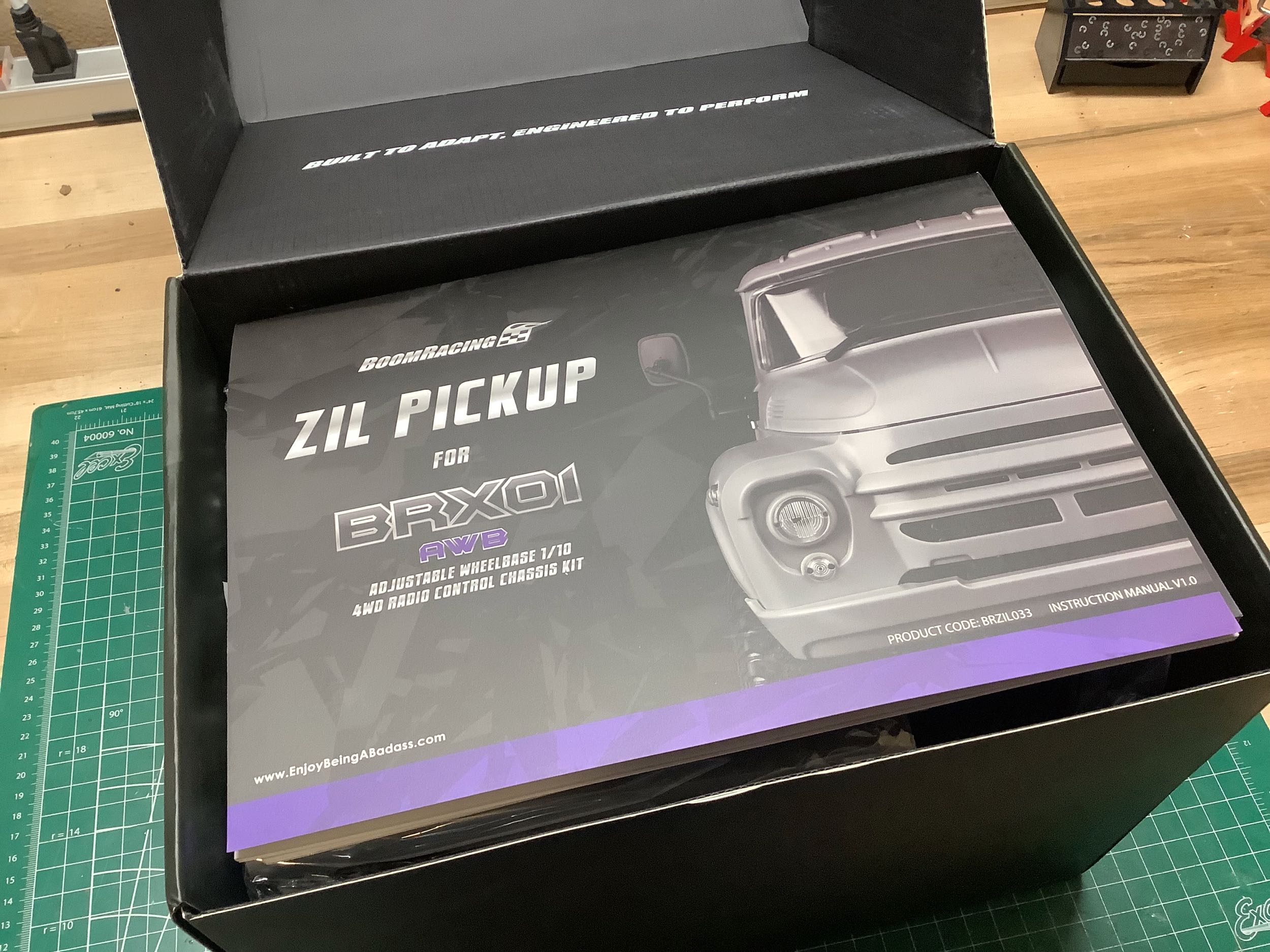
When you open the box, all you see is the manual. This is actually
just the body manual; the chassis manual is another book which is
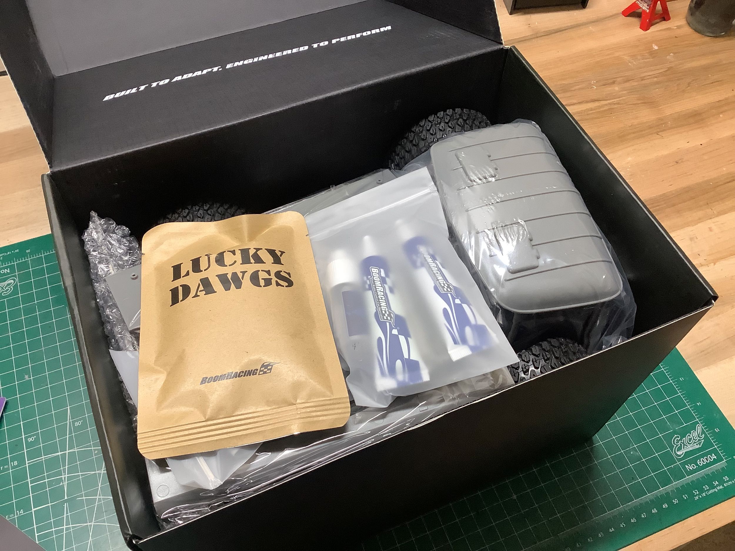
beneath it. The mystery gift is revealed to be a "Lucky Dawgs"
bag. What does that mean? It is a 3D dog that goes together
like a puzzle. No idea what that has to do with a truck.
Apparently it was a promotion that Boom Racing ran for a while.
You can also see the roof of the cab and a bag containing some fluids
(grease, oil, etc.).
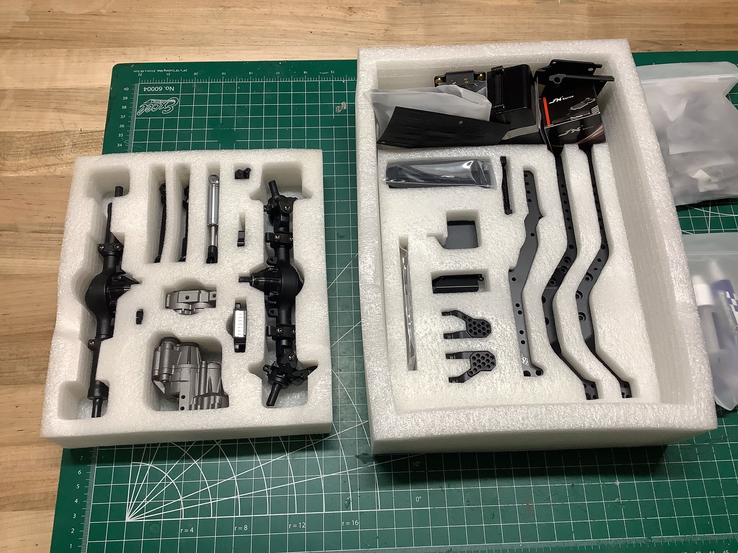
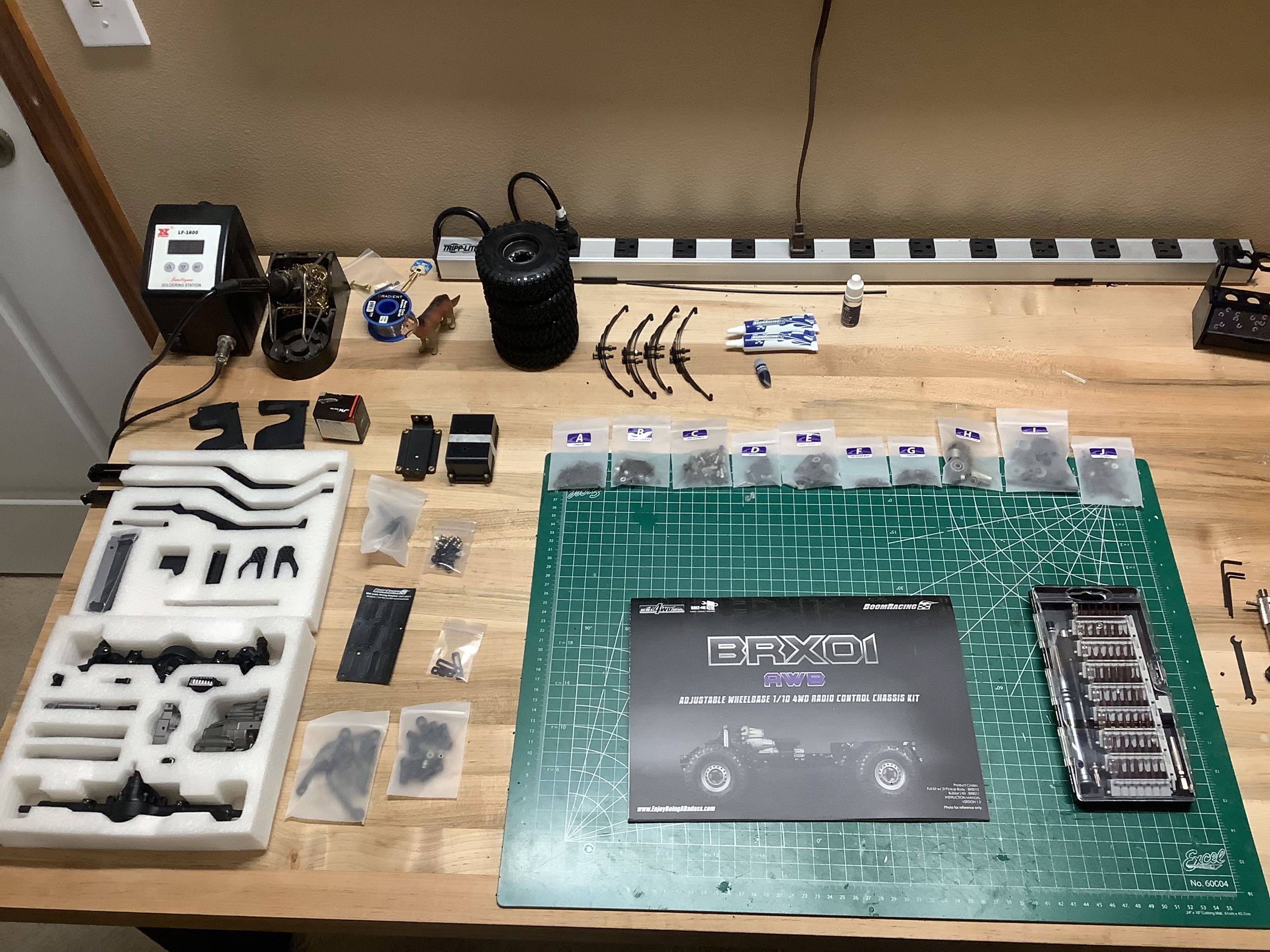
The parts inside are packed very carefully. There are two foam
trays shown on the left which contain the majority of the metal parts
including the chassis rails, axles, shocks, and drive shafts. On
the right I've knolled out all the parts including the hardware bags
(labelled A-J). If you look closely next to the pile of tires, you
can see the "Lucky Dawg" I've assembled supervising my build.
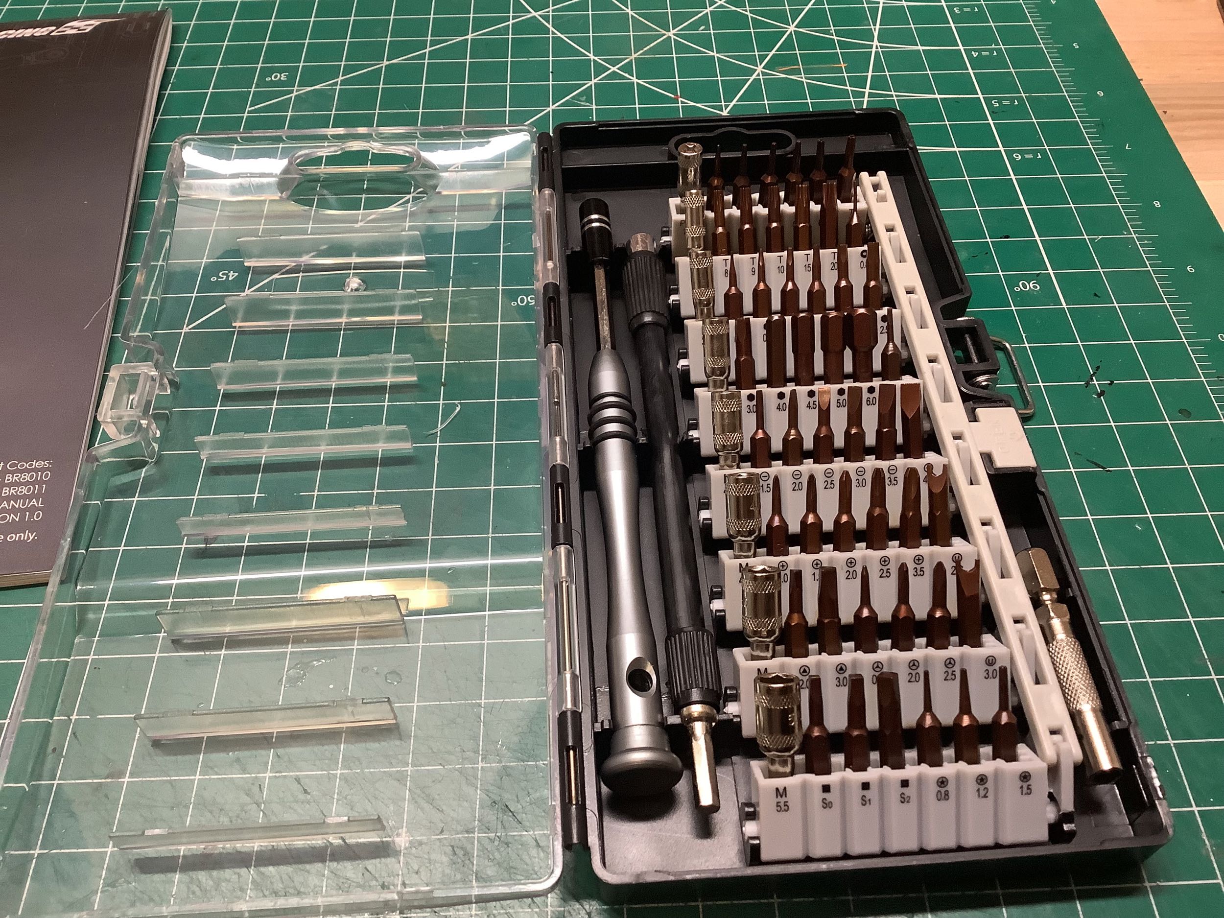
An even bigger surprise was contained with the box, this lovely
miniature tool set. It comes with a driver, a flex cable, 48
driver tips, and 8 sockets.
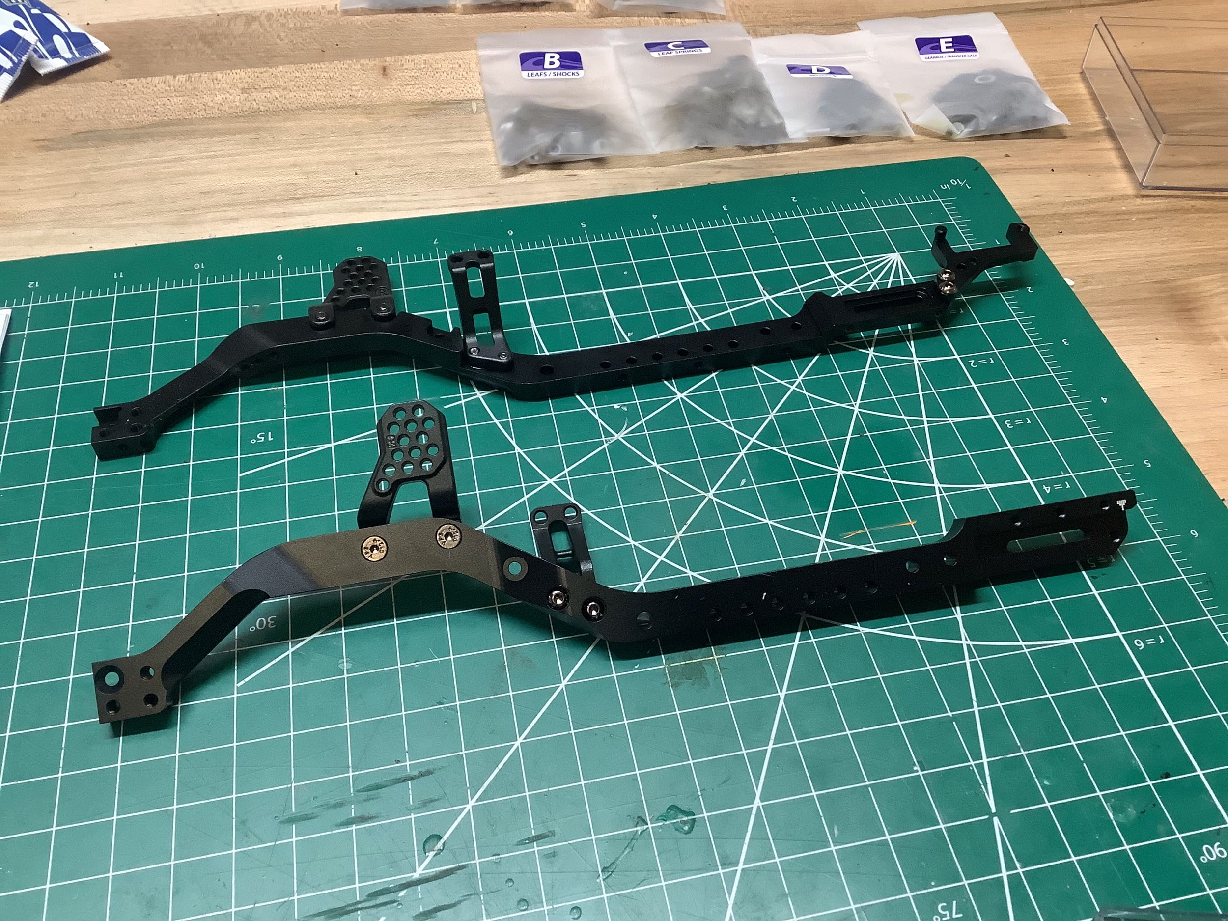
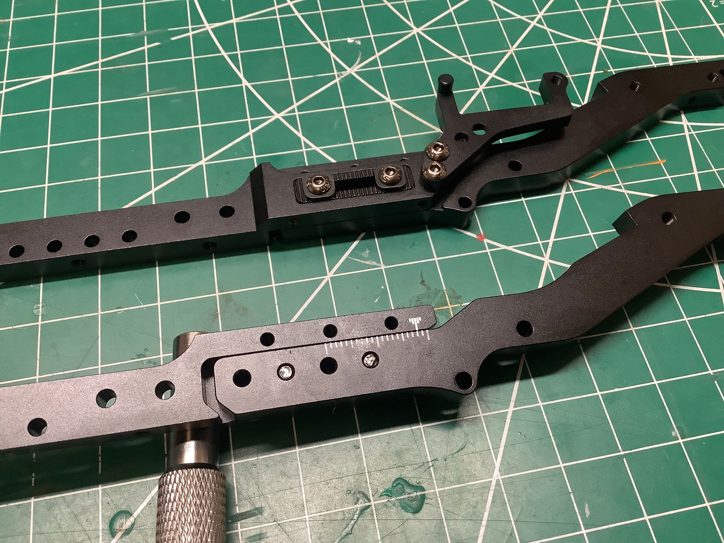
The chassis rails are machined aluminum. The black color seems
more likely to be paint than an anodize coating. On the left I've
added the front shock hoops and motor mounts. The right hand image
shows a detail of how the wheelbase in adjusted. There are two
slots which connect the front part of the chassis rails to the
rear. The lower example shows the painted white scale indicating
the current position which can be adjusted 20mm (265mm to 285mm).
Optional rear chassis rails can increase this all the way to
307mm. You can see that my sample is built 2mm from the shortest
option (267mm). The upper example shows the serrated plates and
washers which lock the length adjustment in place so that there is more
than just friction preventing the chassis sections from drifting
apart. These serrations seem to have a pitch of about 1mm which
means that is the adjustment interval.
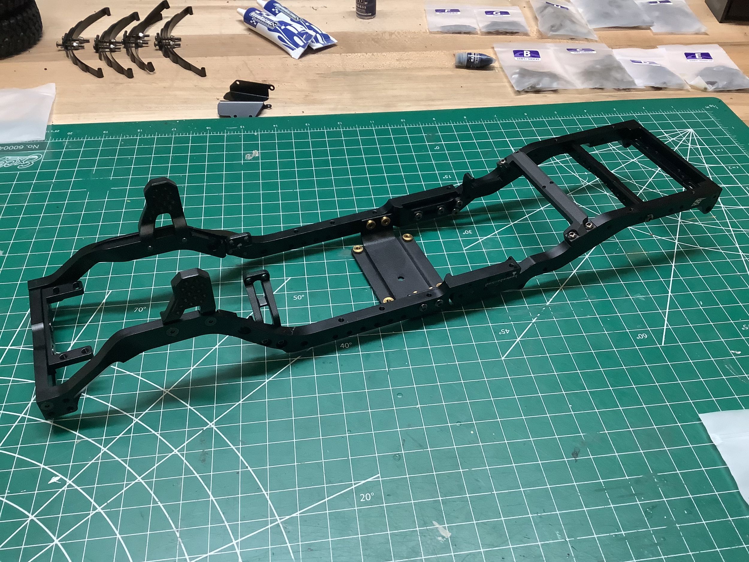
Here is the completed ladder frame. Most of the cross members are
machined aluminum, but the center skid plate is stamped steel with brass
threaded inserts. A lot of screws were required to get to this
point!
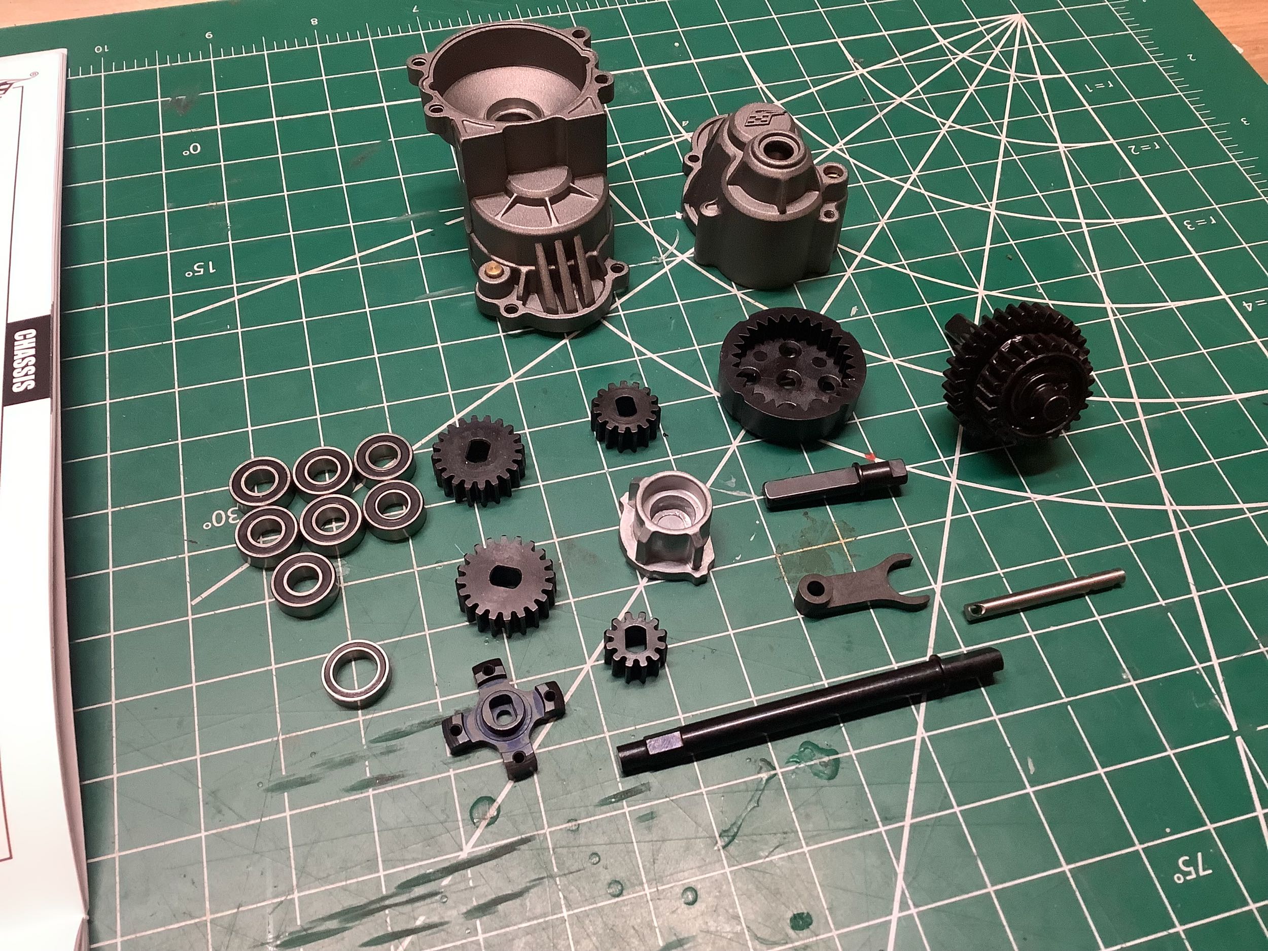
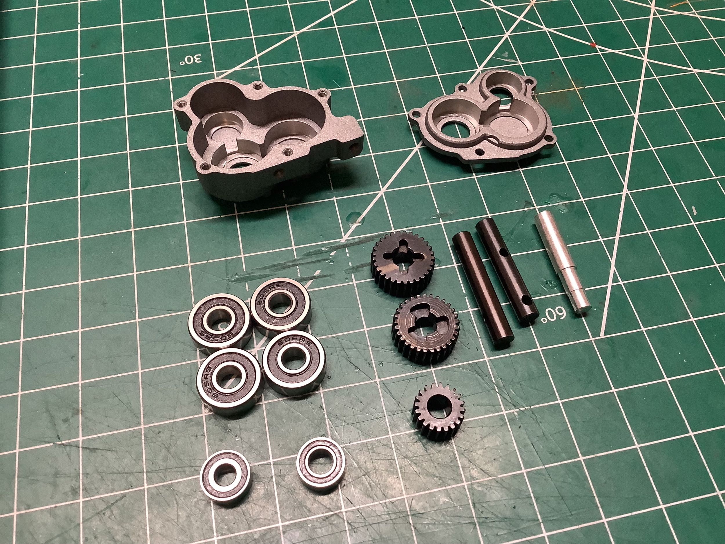
Time to build the transmission which is usually my favorite part.
The housings are cast aluminum and the gears are all steel. Full
rubber shielded ball bearings are included. The part that
accomplishes the two speed shifting is a pre-assembled gear pack shown
on the right of the left hand image. This does not used shift
forks and driving rings like a regular transmission. There are two
gears free to rotate on a shaft, one of which is locked to the shaft at
a time by a translating key. This seems like a structurally weak
design, but it is compact and has so far worked well. The right hand
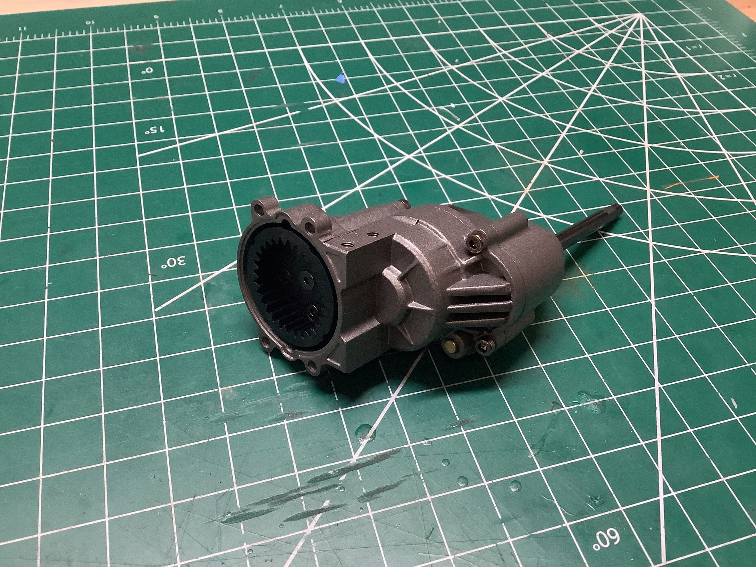
image has the transmission assembled. Inside, you can see the
internal ring gear which is used as an input spur and mates with the
motor pinion. This is another space saving design solution which allows
the motor to be nearly concentric with the transmission housing.
The ring gear is the only plastic part (carbon reinforced).
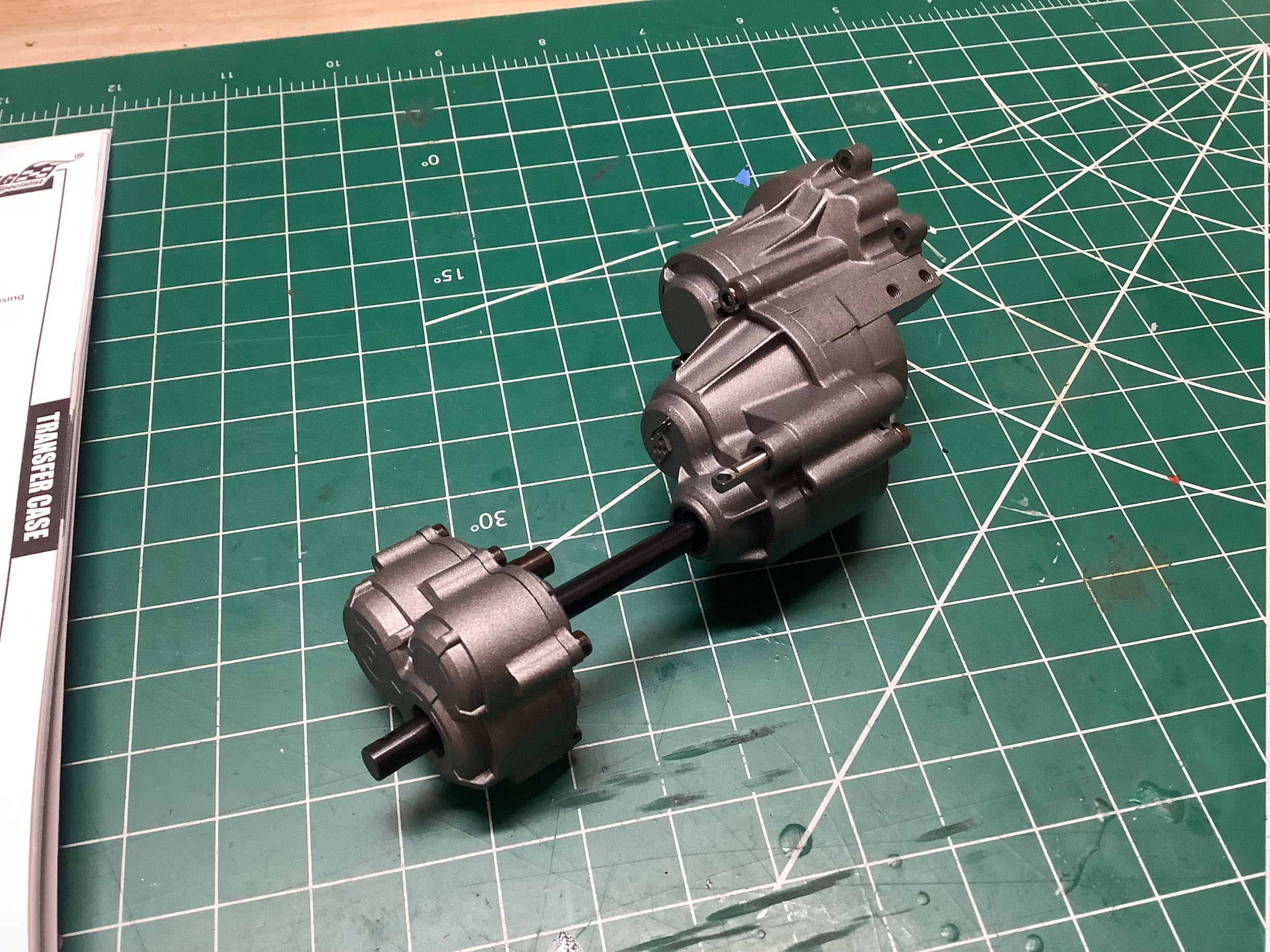
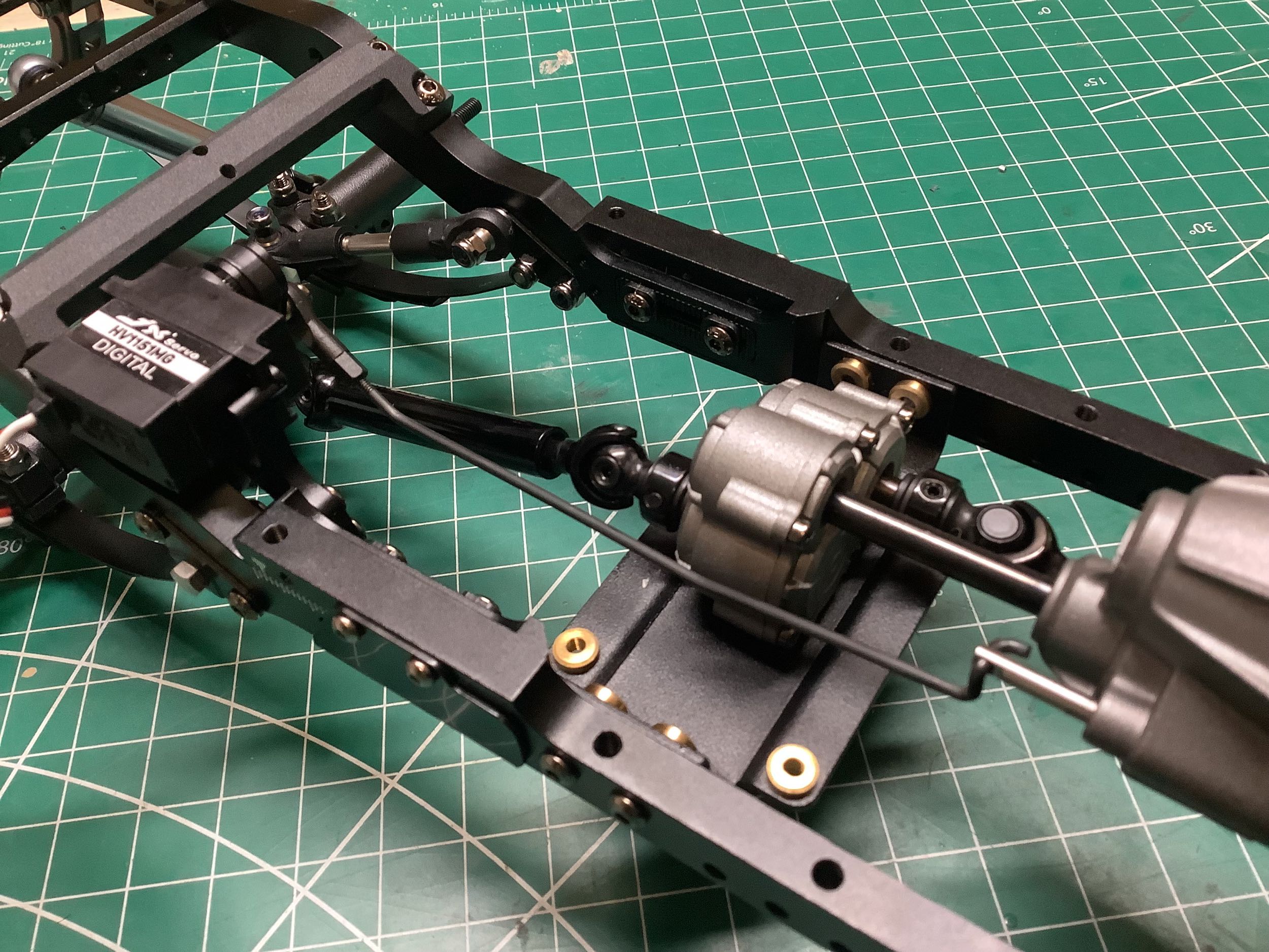
The divorced transfer case is assembled separately and connects to the
transmission with a long steel shaft. You have to be careful with
the assembly at this point because nothing holds the shaft inside the
t-case and it can simply slide out. They will be locked together
by their positioning in the chassis itself. Note that an optional
set of t-case gears are available which provide a 32% overdrive to the
front axle. This is a terrible idea.
At this point in the build I usually can't help but derive the gear
ratios. You can see the large 2.2x difference between low and high
gear. This allows a nice low crawling speed and nice quick
cruising speed.
1st Stage: Motor Pinion-Spur = 28:12
2nd Stage: Adjustable Transmission
Low Gear = 32:12
High Gear = 24:20
3rd Stage: Transmission Output = 20:15
4th Stage: Transfer Case = 29:20
5th Stage: Differential Ring-Pinion = 30:8
Final Drive Ratio
Low Gear = 45.1:1
High Gear = 20.3:1
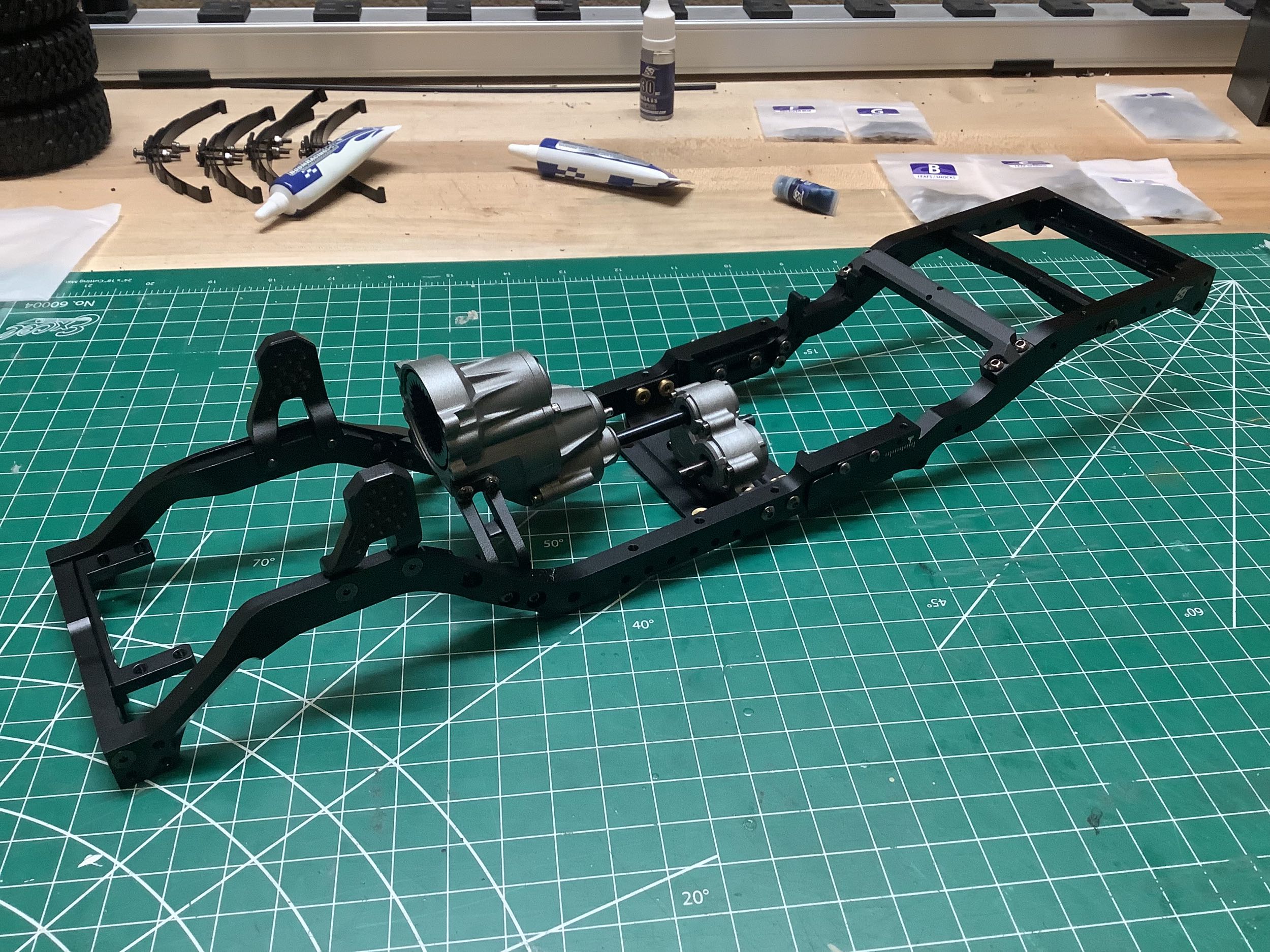
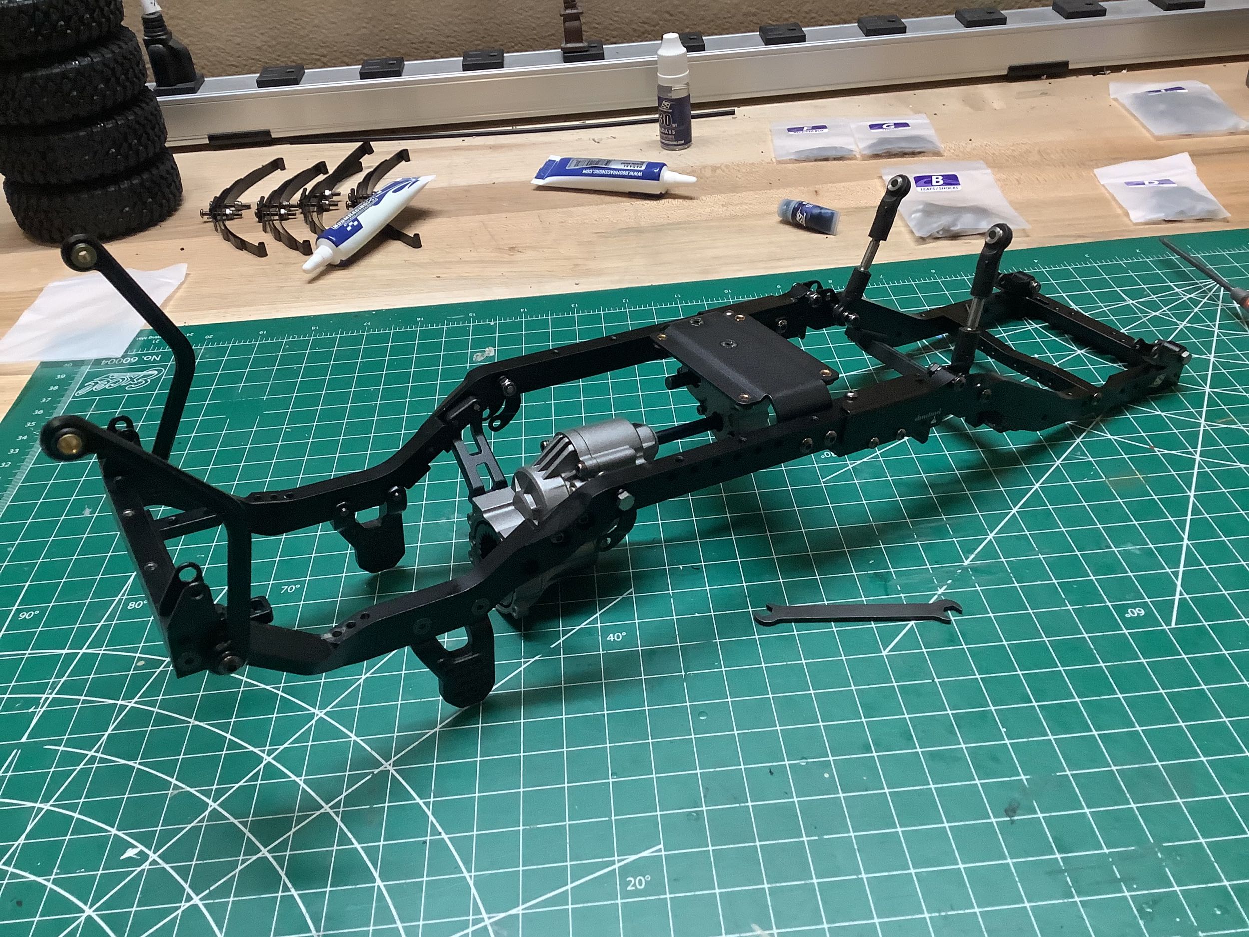
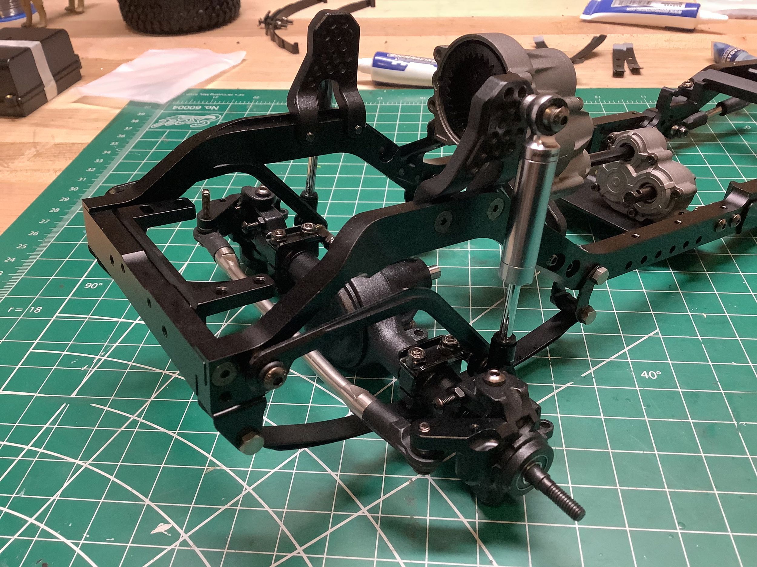
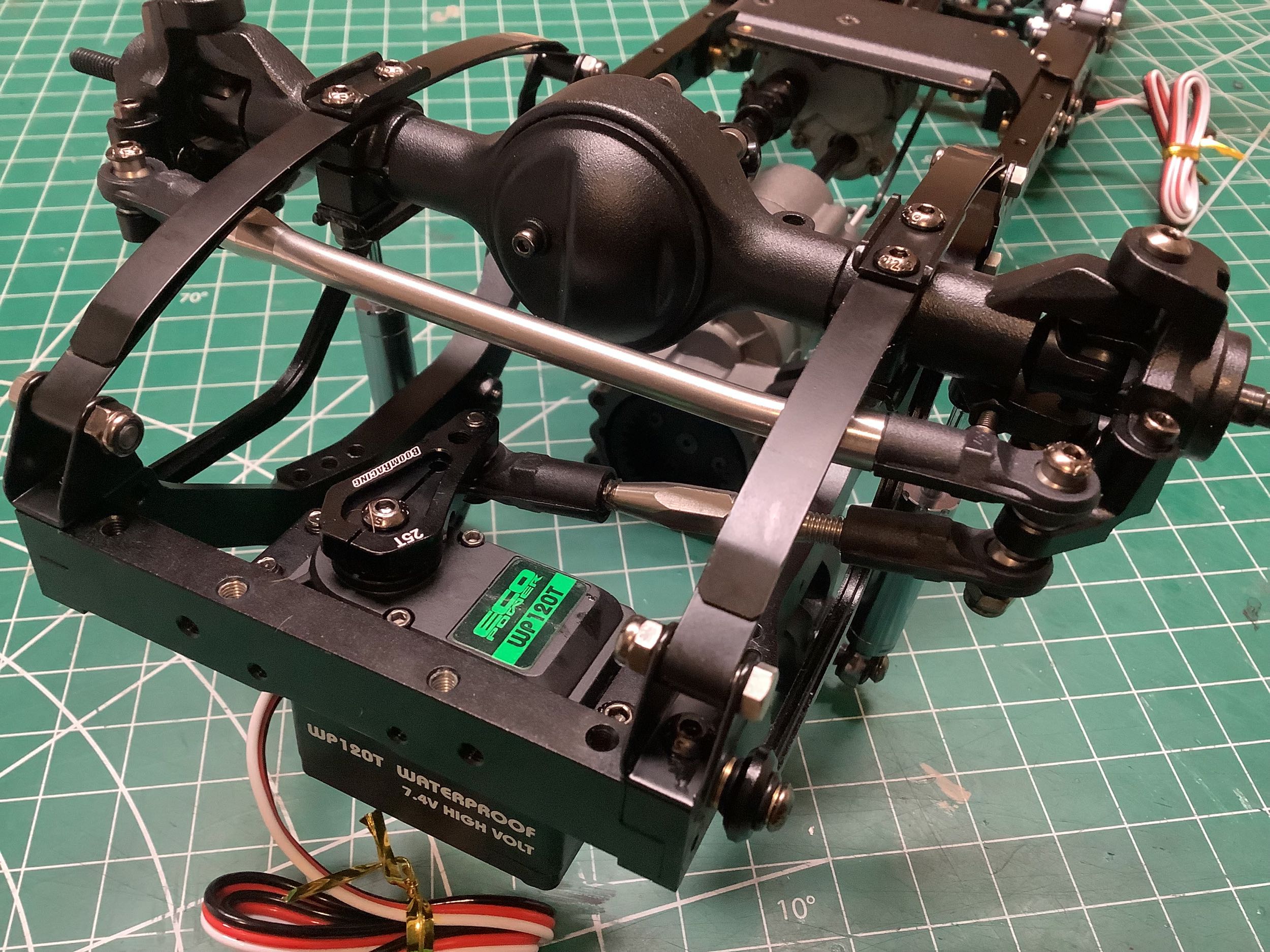
Now the transmission and transfer case can be installed in the chassis
as shown. On the right I'd started the suspension which is very
unusual. Typically when a chassis uses leaf springs, the spring
themselves perform the centering and longitudinal support
functions. In this case, the suspension adds anti-wrap bars in
both the front and rear. The front bars are kinked longitudinal
links that pivot at the front cross member. The rear bars and
triangulated tie rods. These are typically used to prevent wheel
hop under very high torque and are certainly not required on this RC
chassis, but they do add to the scale realism.
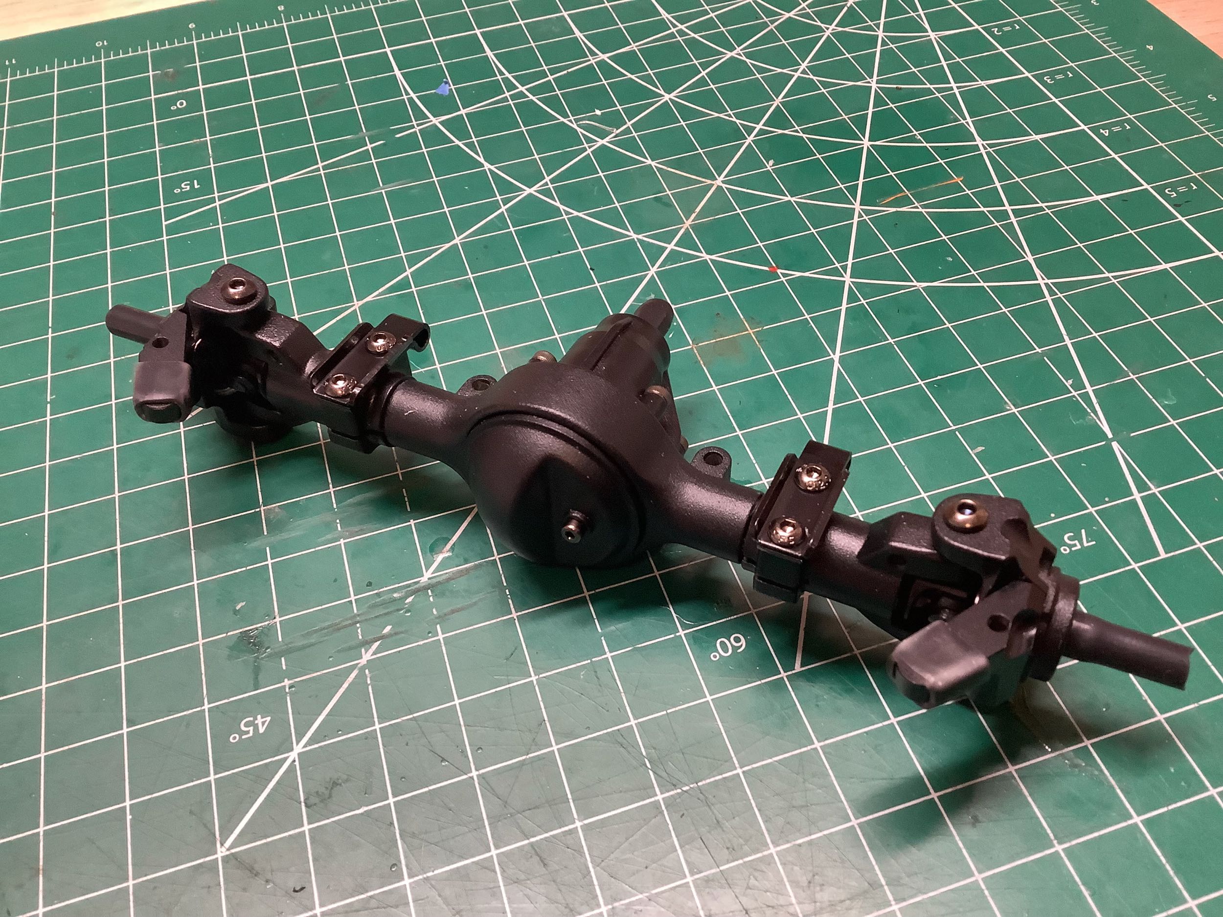
The front and rear axles come pre-assembled. Usually this offends
me as a kit builder so I tear them down and rebuild them. In this
case, removal of the third member revealed that everything inside was
very nicely greased so I actually decided to leave them alone. The
differential housing contains a locked spool, so no differential action
is possible. The pinion enters the housing above center, so this
means the ring and pinion use hypoid gears. I've installed the
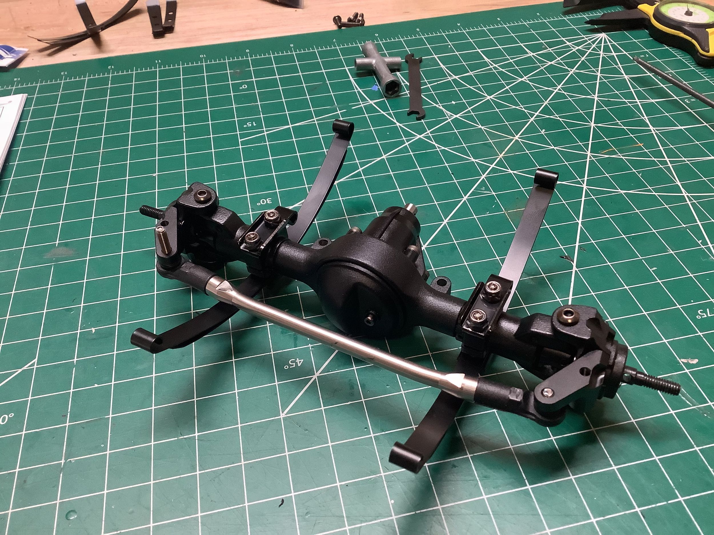
leaf springs and steering link on the right. The kit comes with 4
leaves for each set, but by default the front setup uses on 2 leaves and
the rear uses 3. Even though the steering link is in front of the
axle, the steering cranks are aligned with the king pins resulting in
parallel steering geometry, not reverse Ackerman.
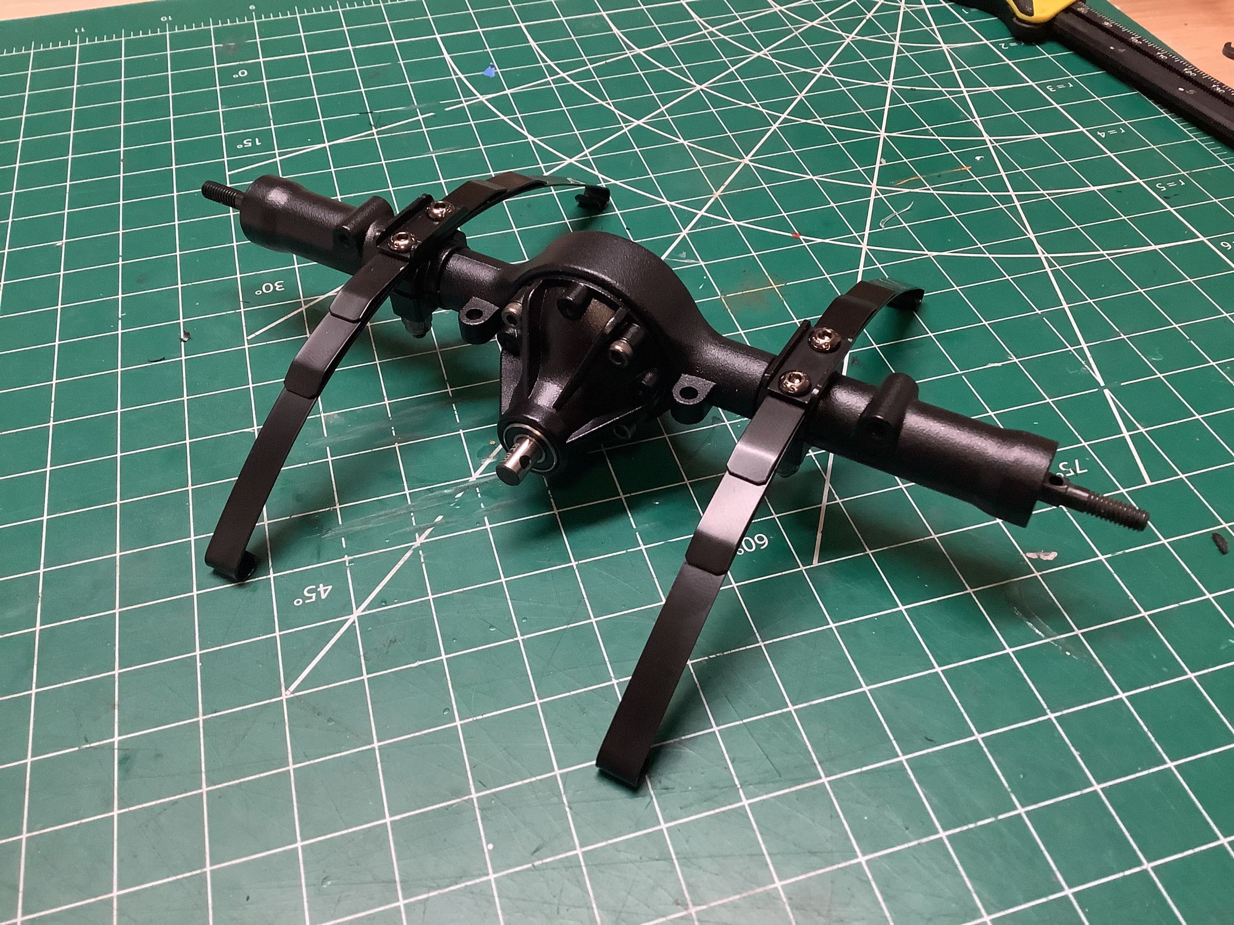
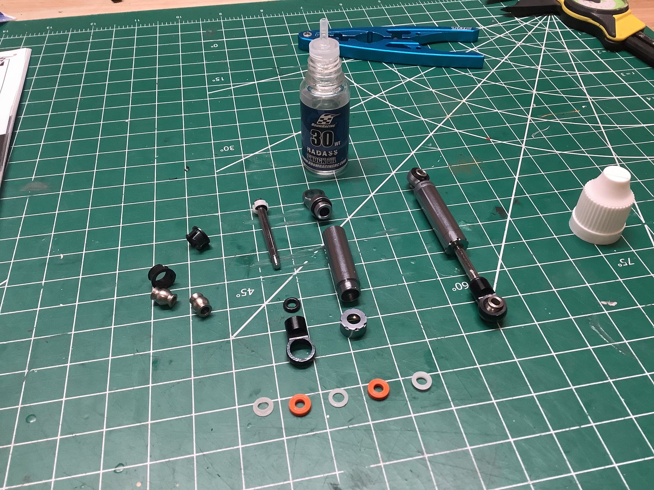
Here I've installed the leaf springs on the rear axle as well. An
exploded view of the shocks in shown on the right. They have very
little internal volume so provide minimal damping, but not much is
needed. The shock housing and caps are aluminum.
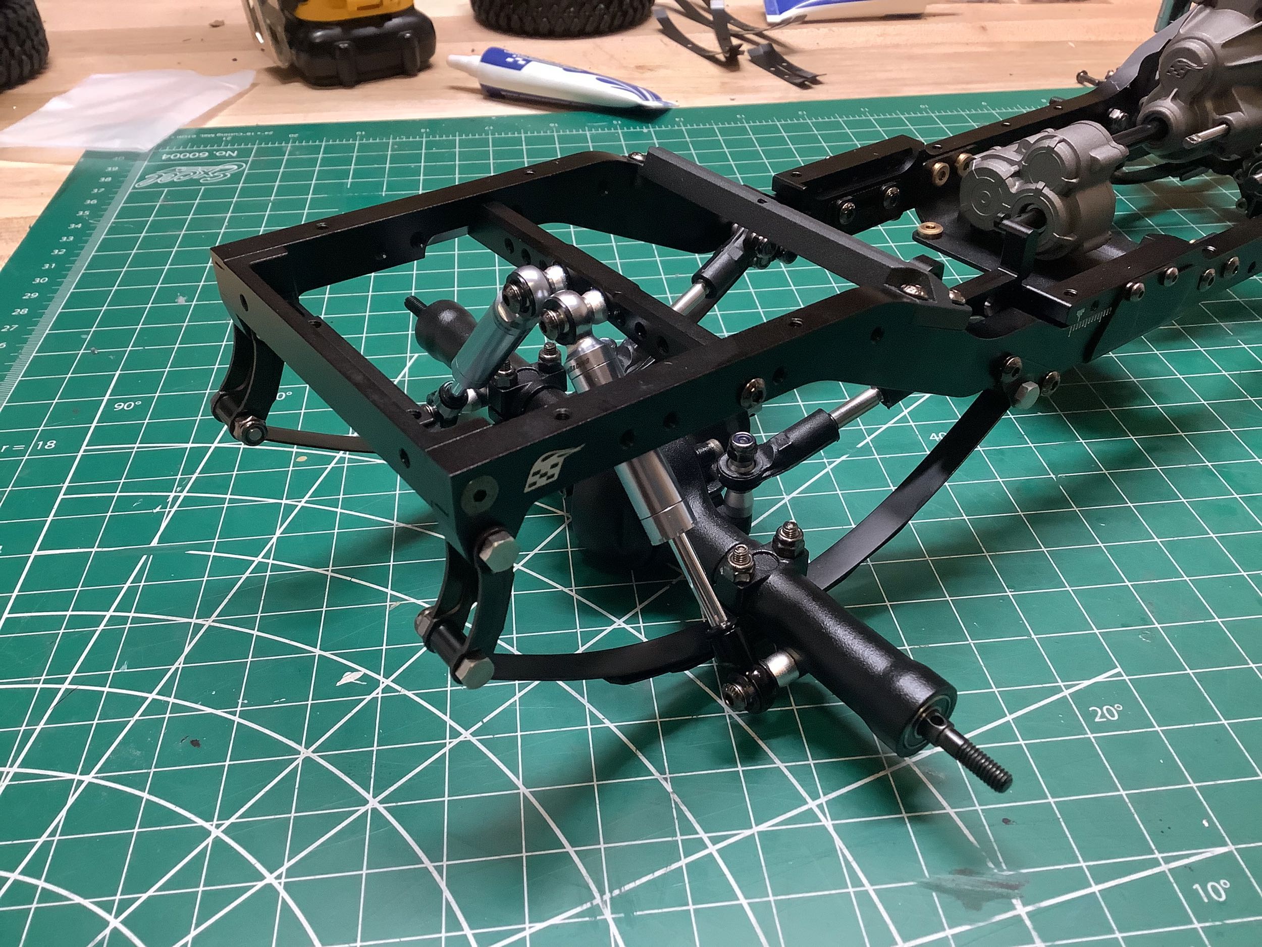
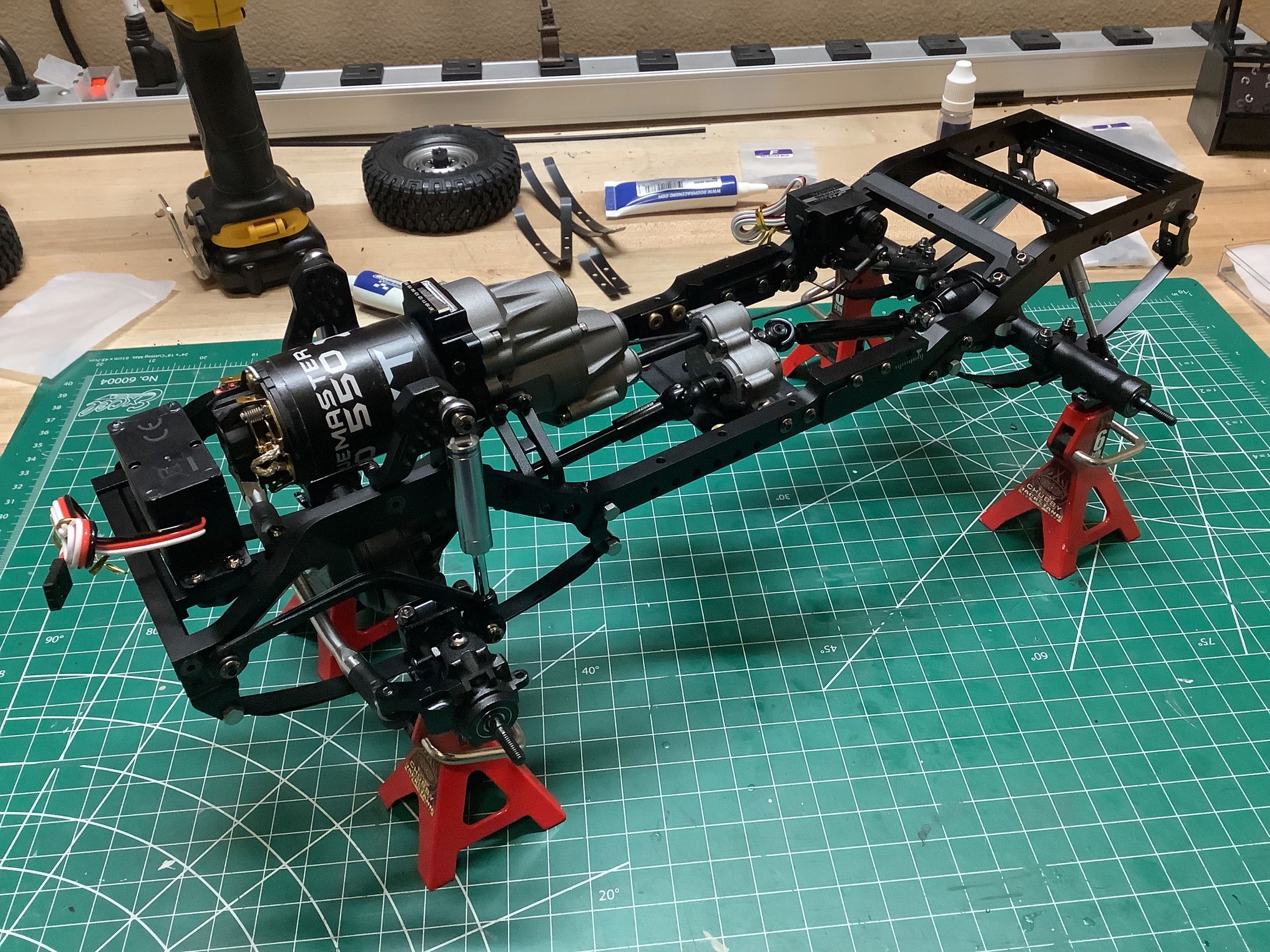
Here are the front and rear axles installed on the vehicle, including
attachment of the anti-wrap bars. Note the diagonal positioning of
the rear shocks to leave room for the full depth bed.
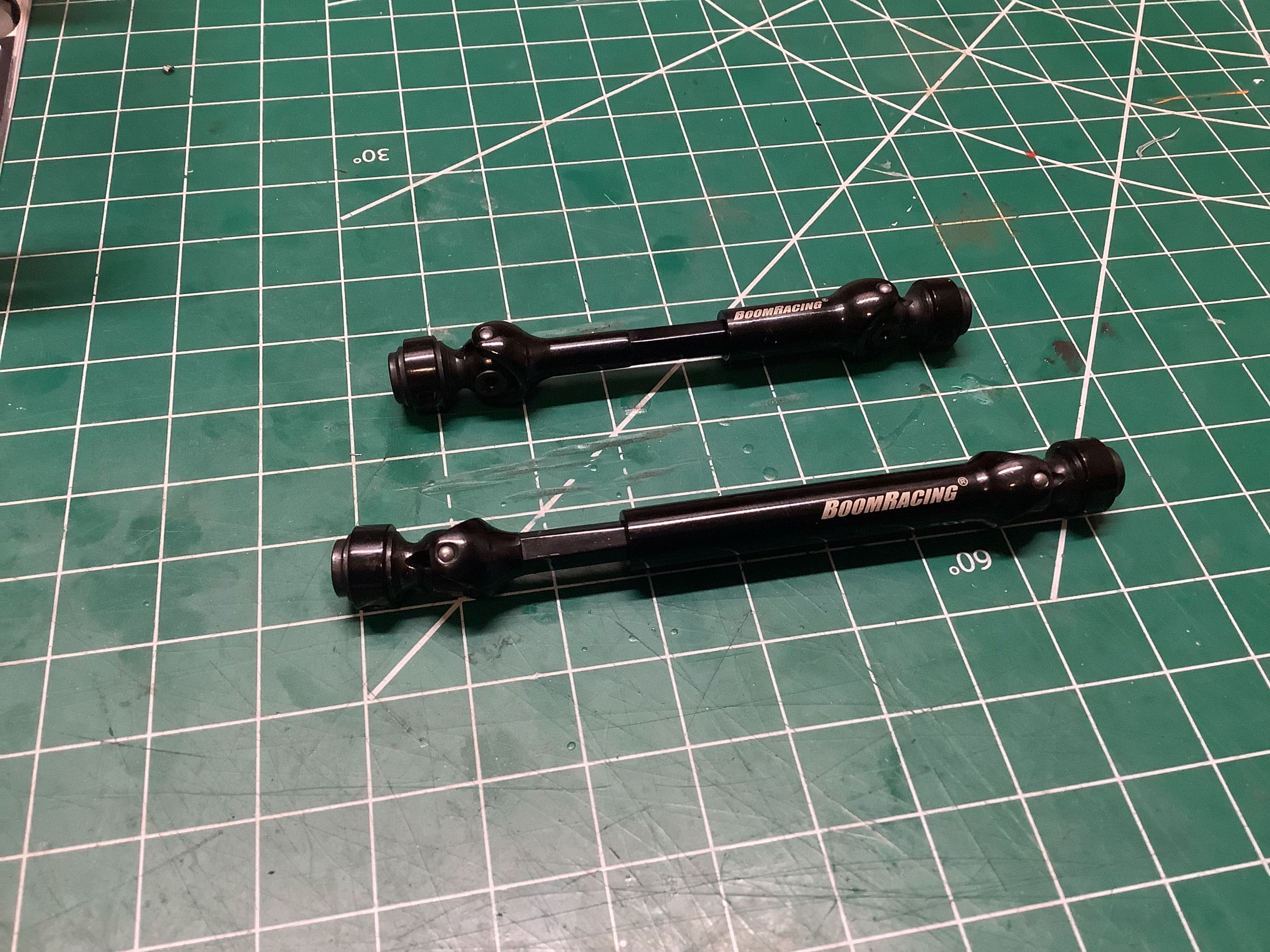
These steel universal drive shafts are seriously sturdy. Although
they are telescoping units, different lengths are required for the front
and rear.
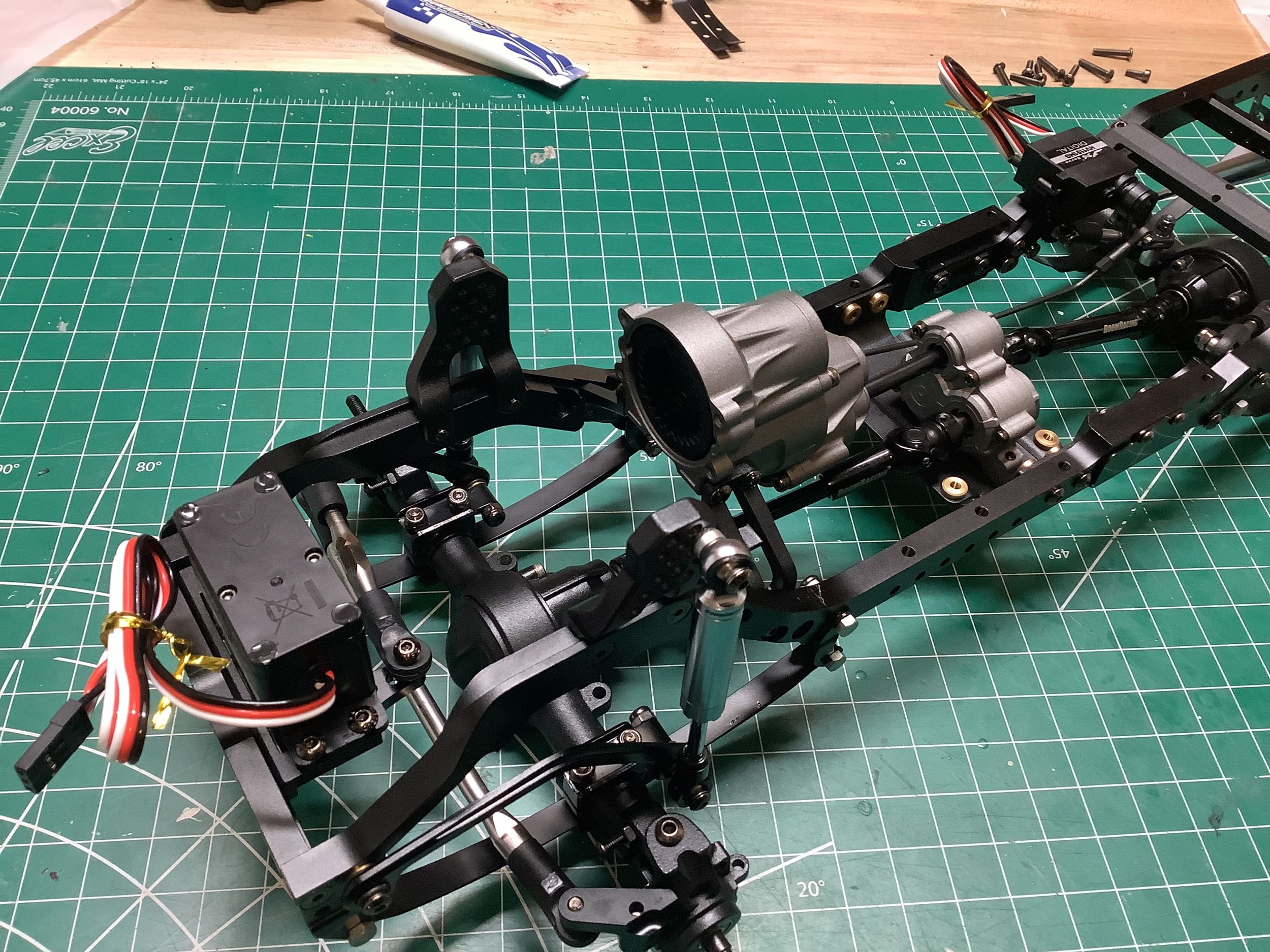
The model uses a chassis mounted servo at the very front of the ladder
frame and comes with nice machined aluminum clamping servo horn.
There is no panhard rod so the suspension is susceptible to a bit of
bump steer, though it is not really noticeable off road.
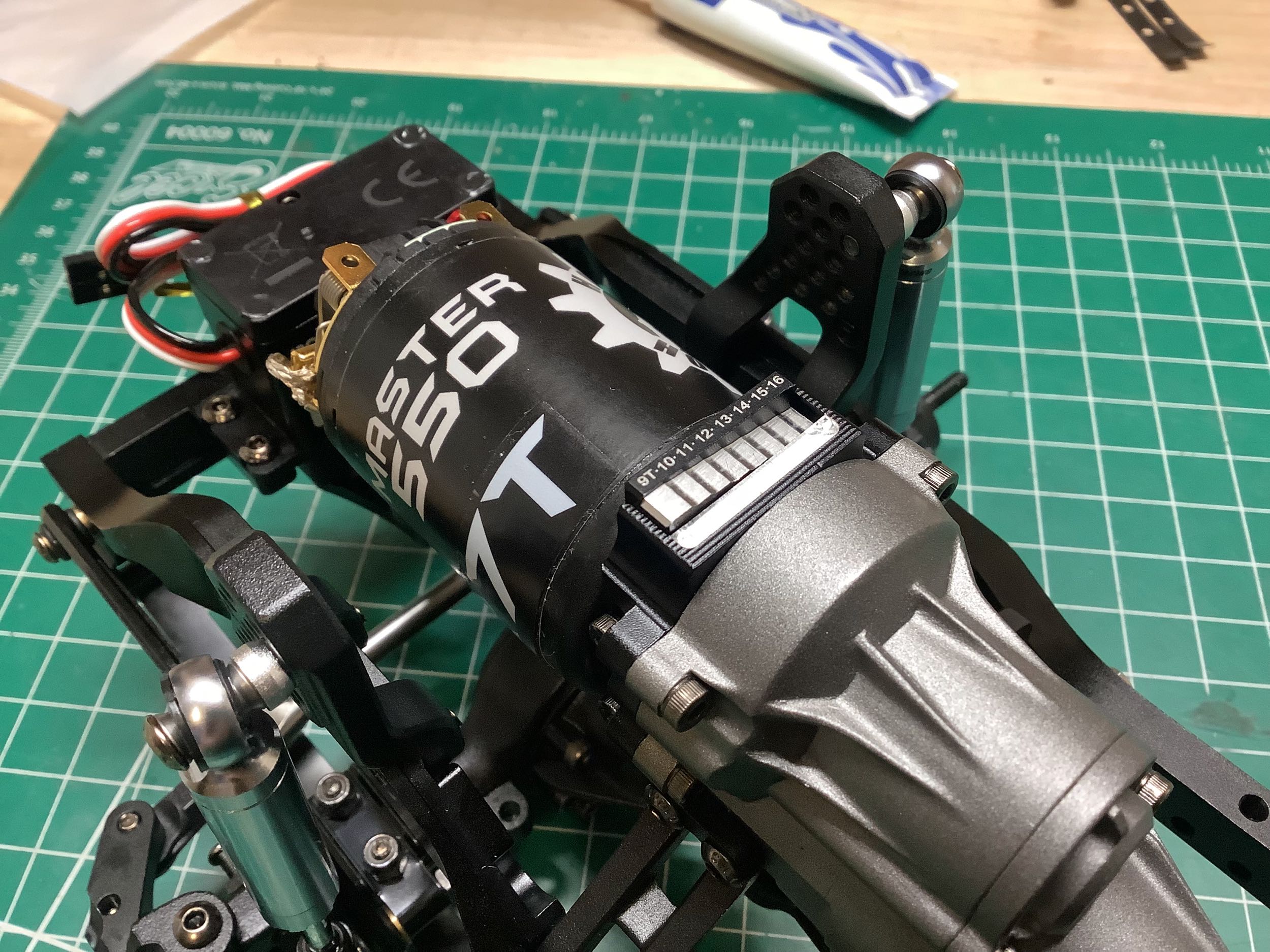
I chose a Holmes Hobbies 550 sized brushed motor for this project.
This chassis has a unique gear mesh adjustment method. The
picture on the left shows a stepped scale with numbers on it. The
idea is that you choose the number of pinion teeth (in my case, 12T),
then adjust the whole motor mount vertically until the matching numbered
step aligns. Something like this is necessary because of the
internal spur gear which it is impossible to see for visual
adjustment. Sadly, it doesn't work. I adjusted it to the 12
step and the mesh was so tight that the motor could barely turn. I
had to manually make changes entirely by ear to try to get a smooth
mesh. Even then, this is a very noisy gearbox.
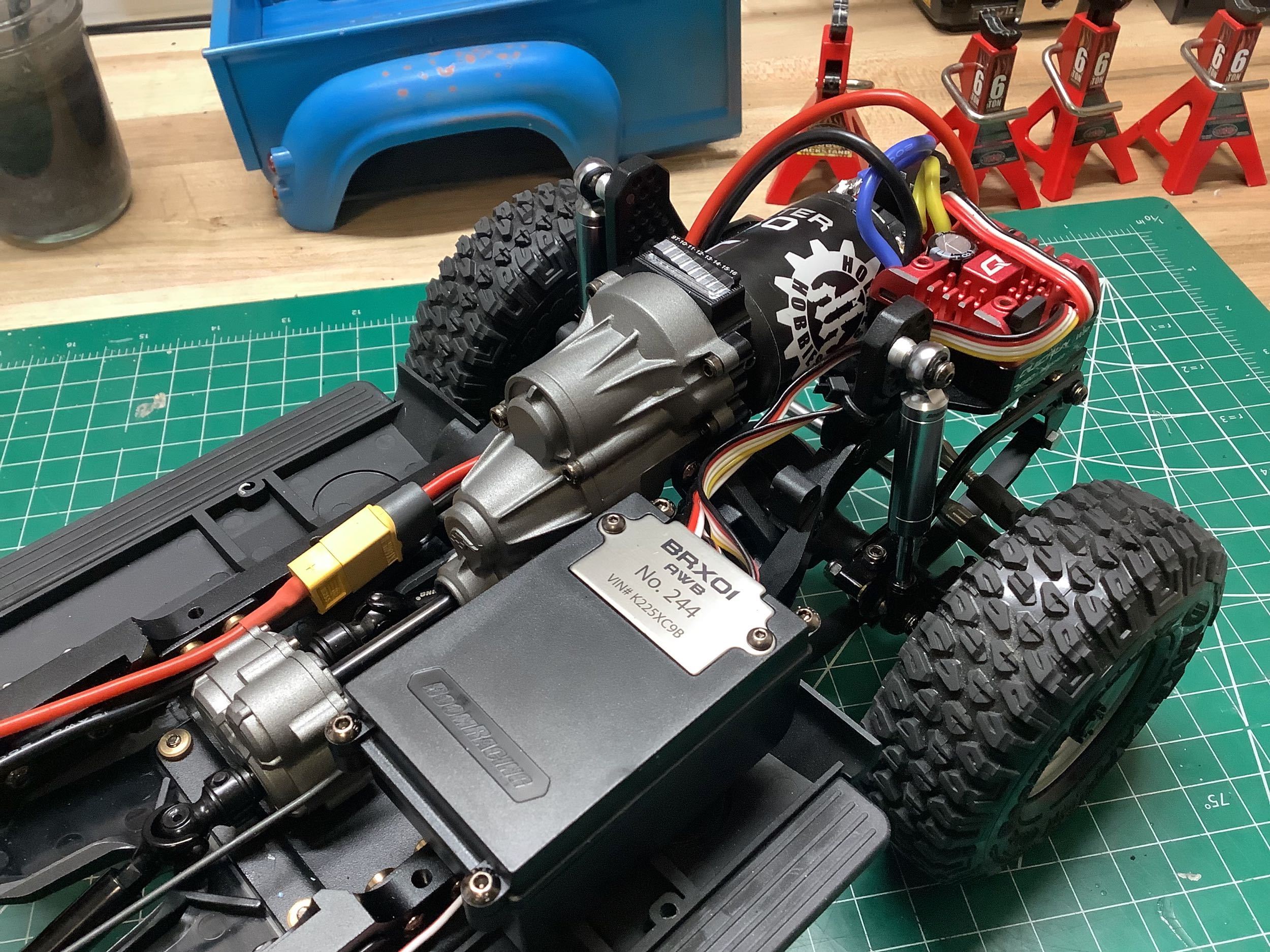
The picture on the left shows the shift linkage. The kit actually
came with a small scale, metal geared servo just the right size and
power for shifting the gearbox. It connects with a long link as
shown, routed carefully below the body. On the right I've added
the copious receiver box. The ESC is not intended to go inside, so
that leaves a whole lot of room for my tiny, 5-channel receiver.
The box is waterproof, but so is my receiver so I wasn't too concerned
about it. Also note the "serial number" on the name plate which
matches the license plates. The ESC installs on a platform next to
the motor, and will be accessible under the hood. The battery
will be housed in a box in the bed of the truck, not in a tray on the
chassis.
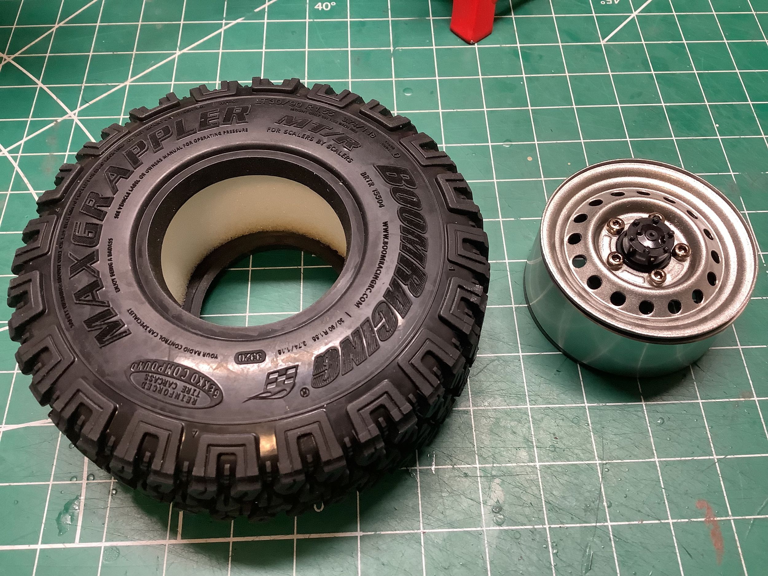
The model came with stamped steel beadlock wheels and extremely detailed
scale tires. Look at the lettering on those tires! There is
also a threaded center cap that hides the lock nut used to install the
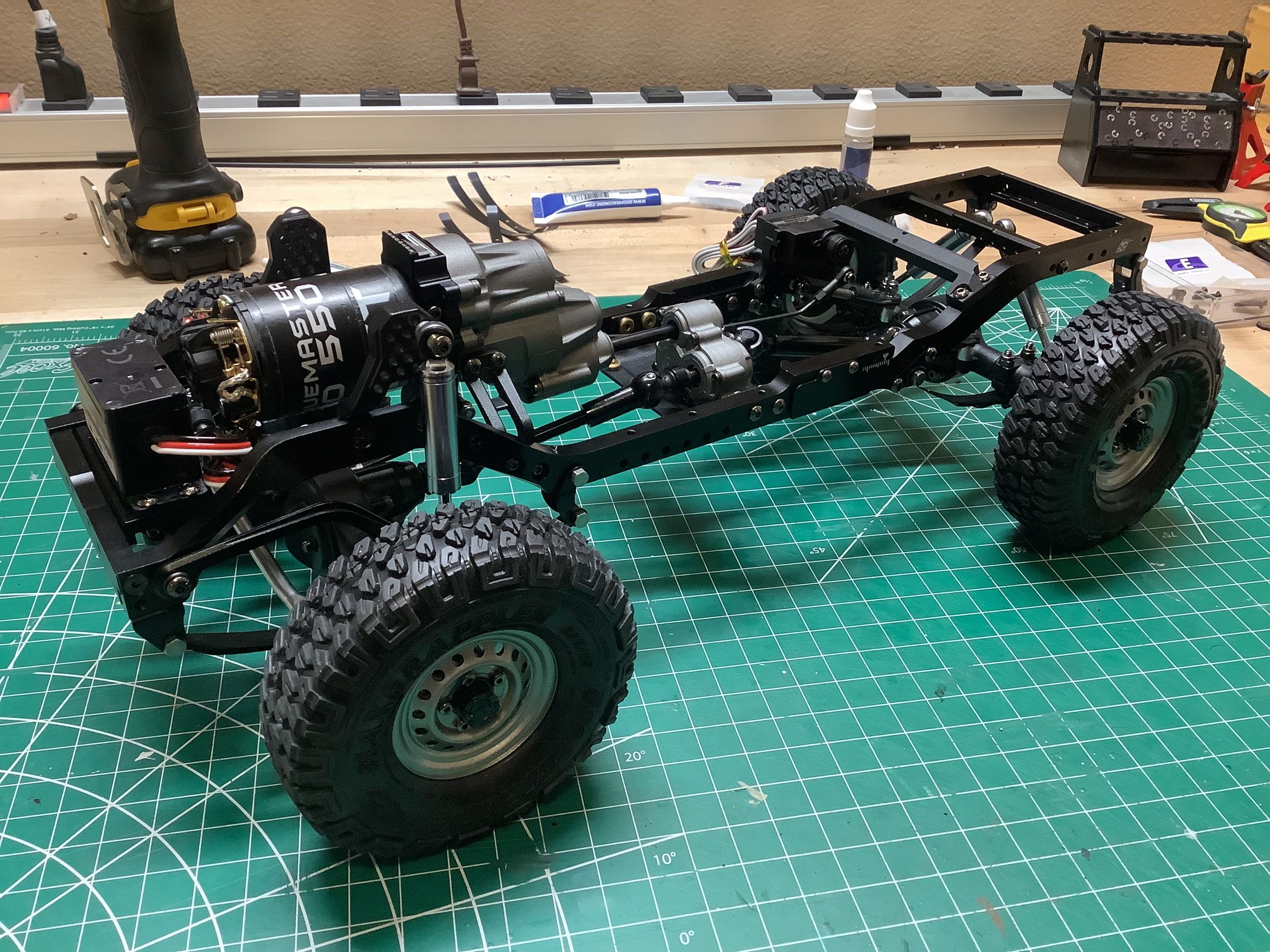
wheel on the axle. The picture on the right shows the completed
chassis.