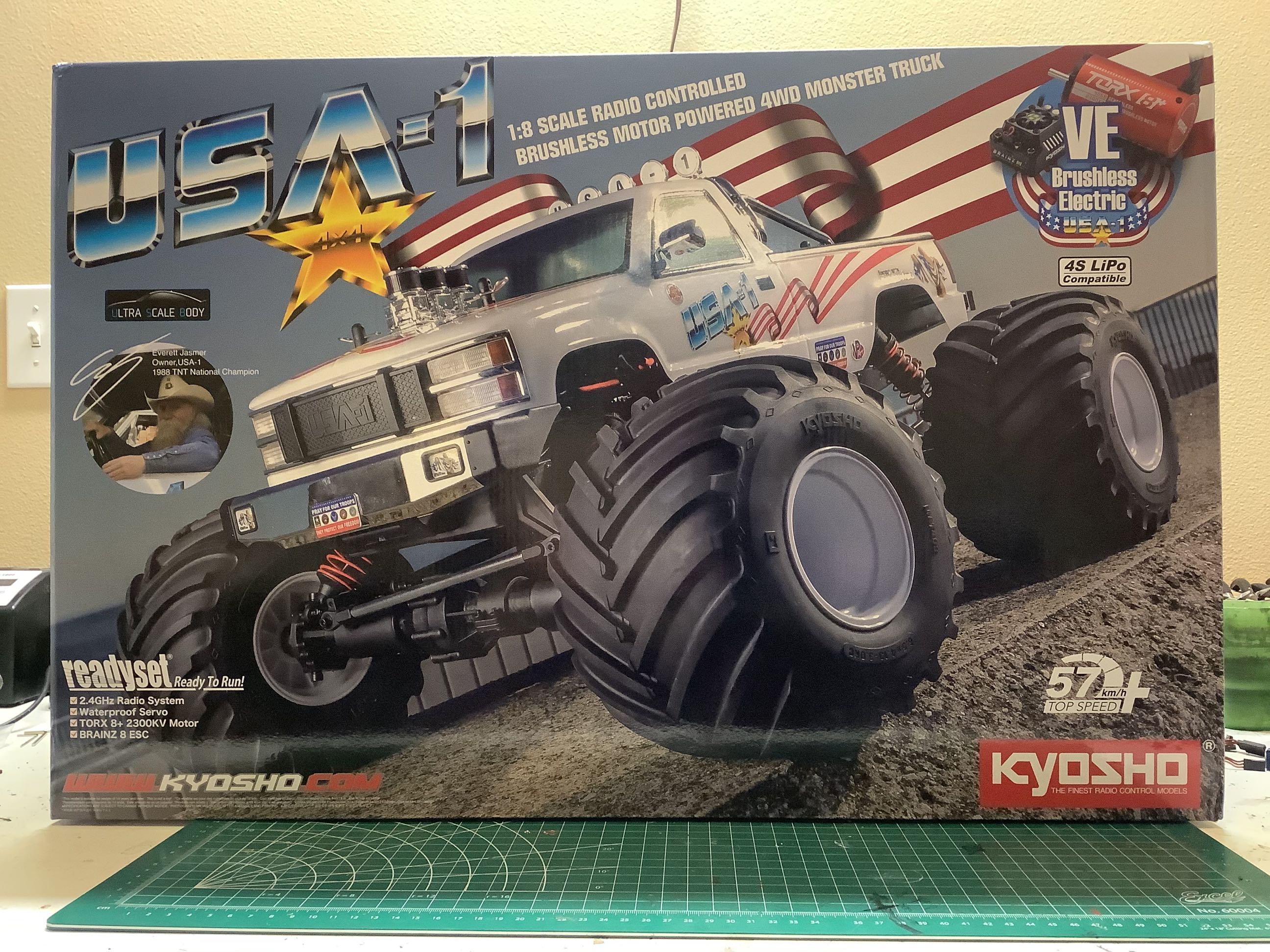
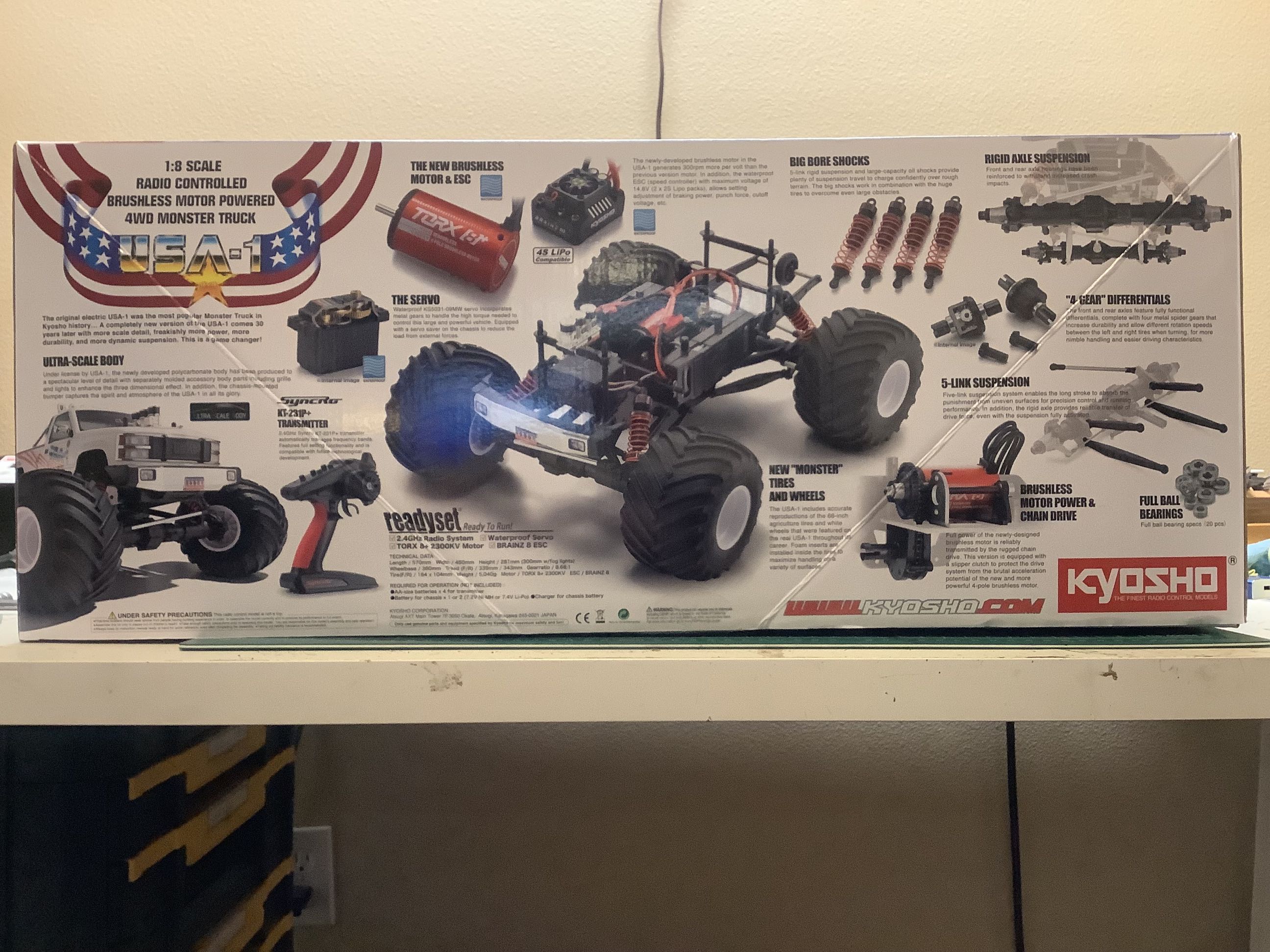
The pre-assembled USA-1 comes in a predictably gigantic box. The features are highlighted in detail on the bottom of the box as shown.
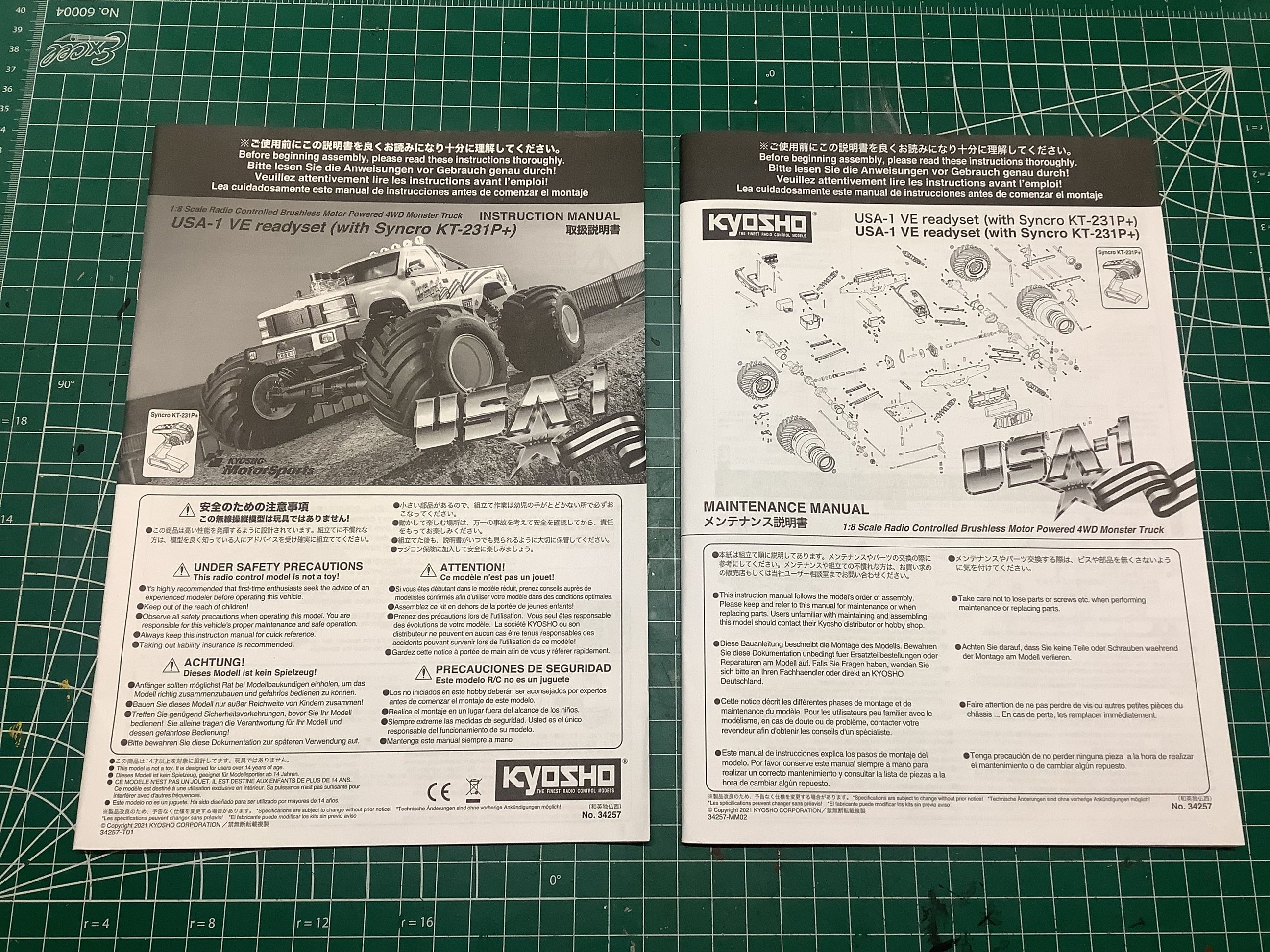
Here's a bonus I wasn't expecting. In additional to the RTR running manual, this model came with a full build manual (left). This allowed me to do what I love to do most with RTR's: tear it down to the bones and build it from scratch.
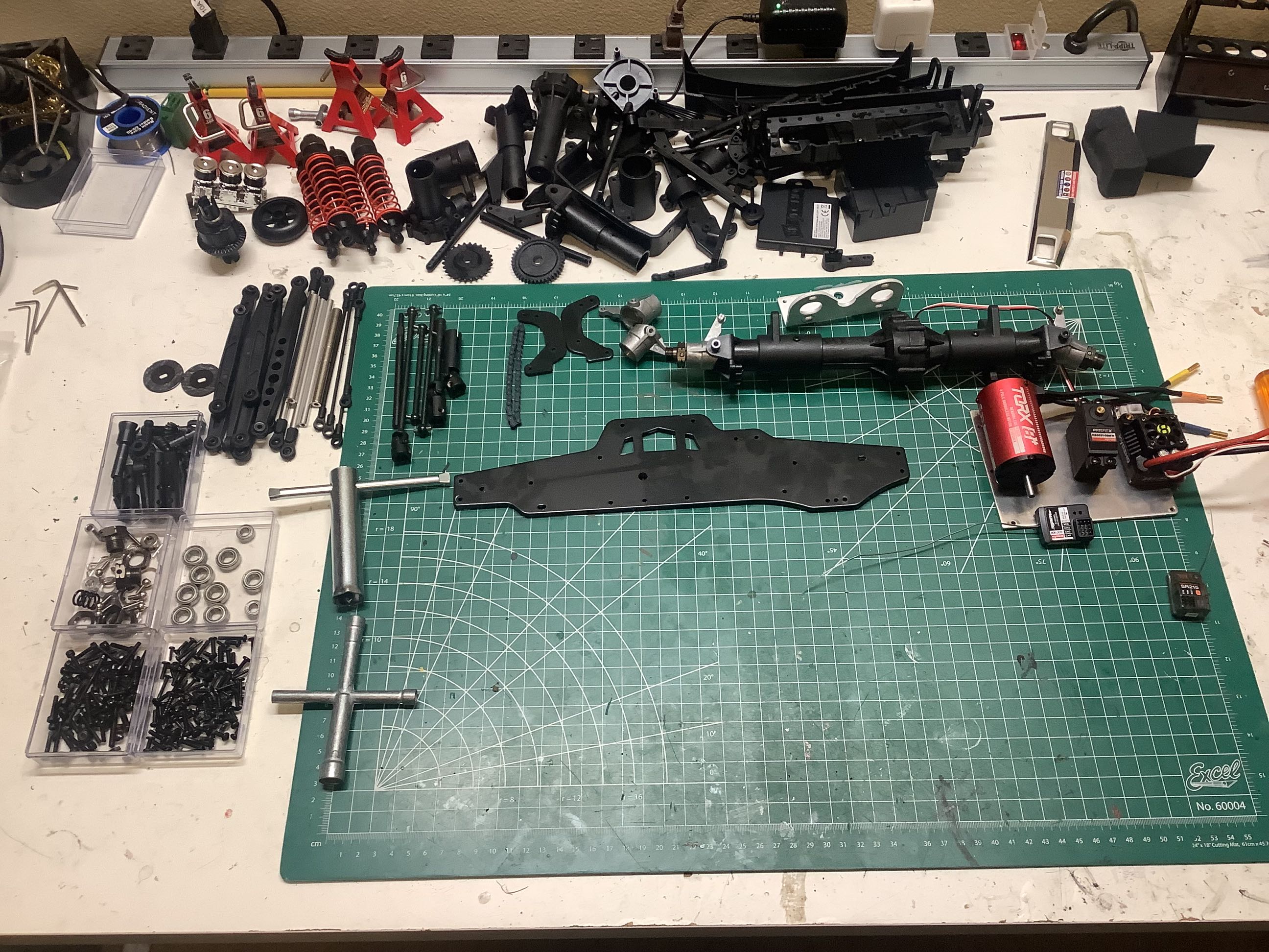
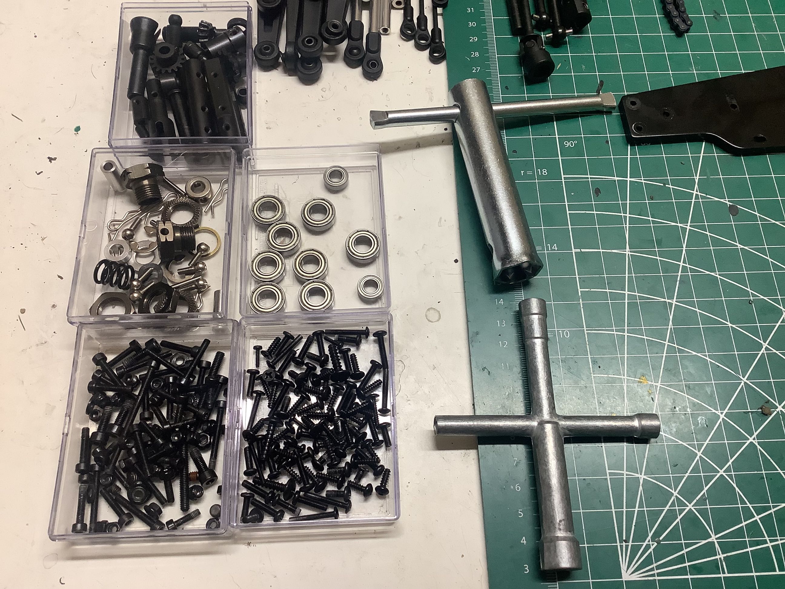
These images show the results of my tear down. You may note that I've only disassembled one of the axles to see how it goes together. The other is pretty much the same so I left it alone. I also did not open up the differentials or shocks since I didn't want to refill them. On the right you can see the piles of hardware along with the large assembly tools that came with the kit. It's amazing how much steel there is in this model.
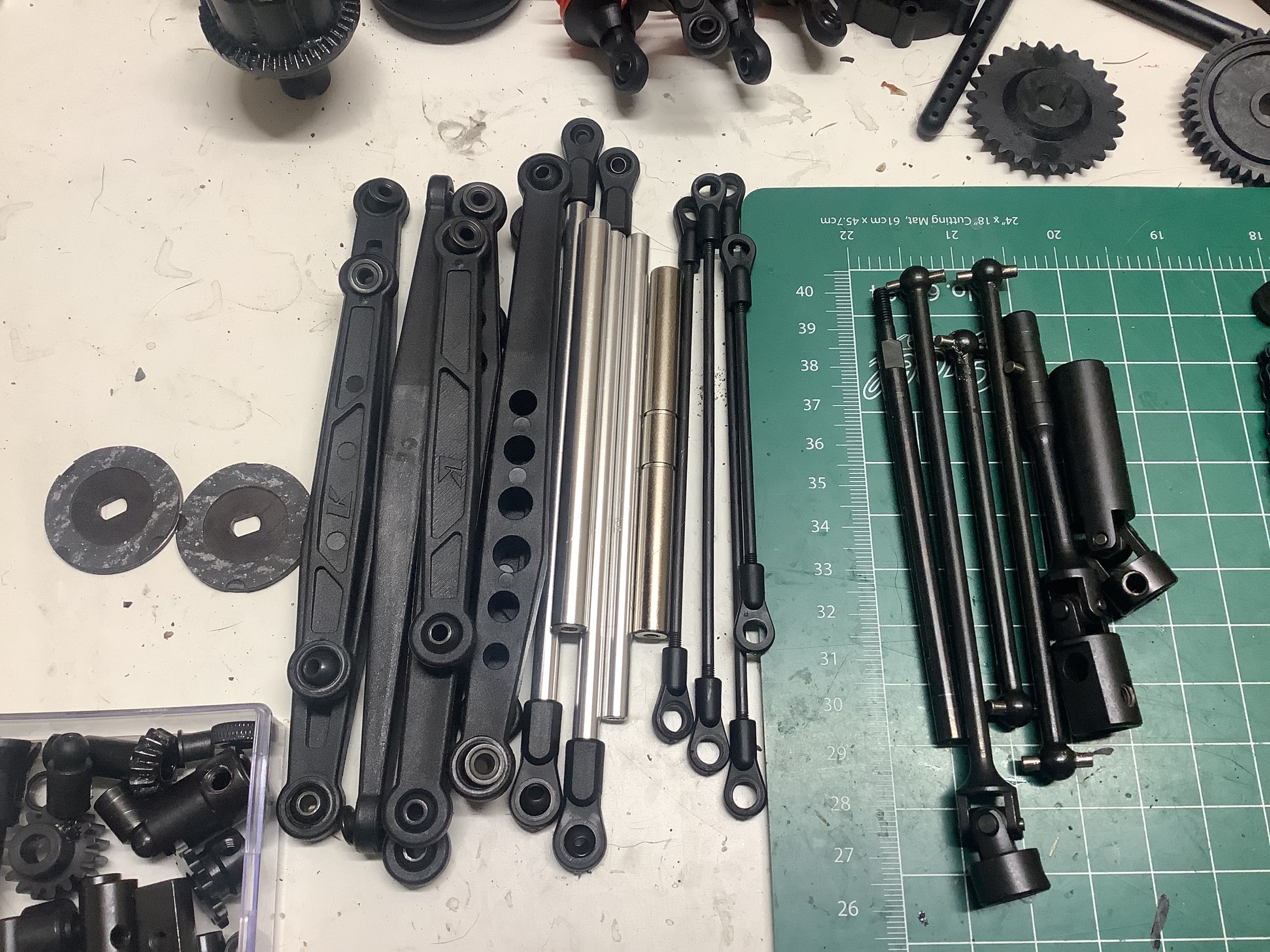
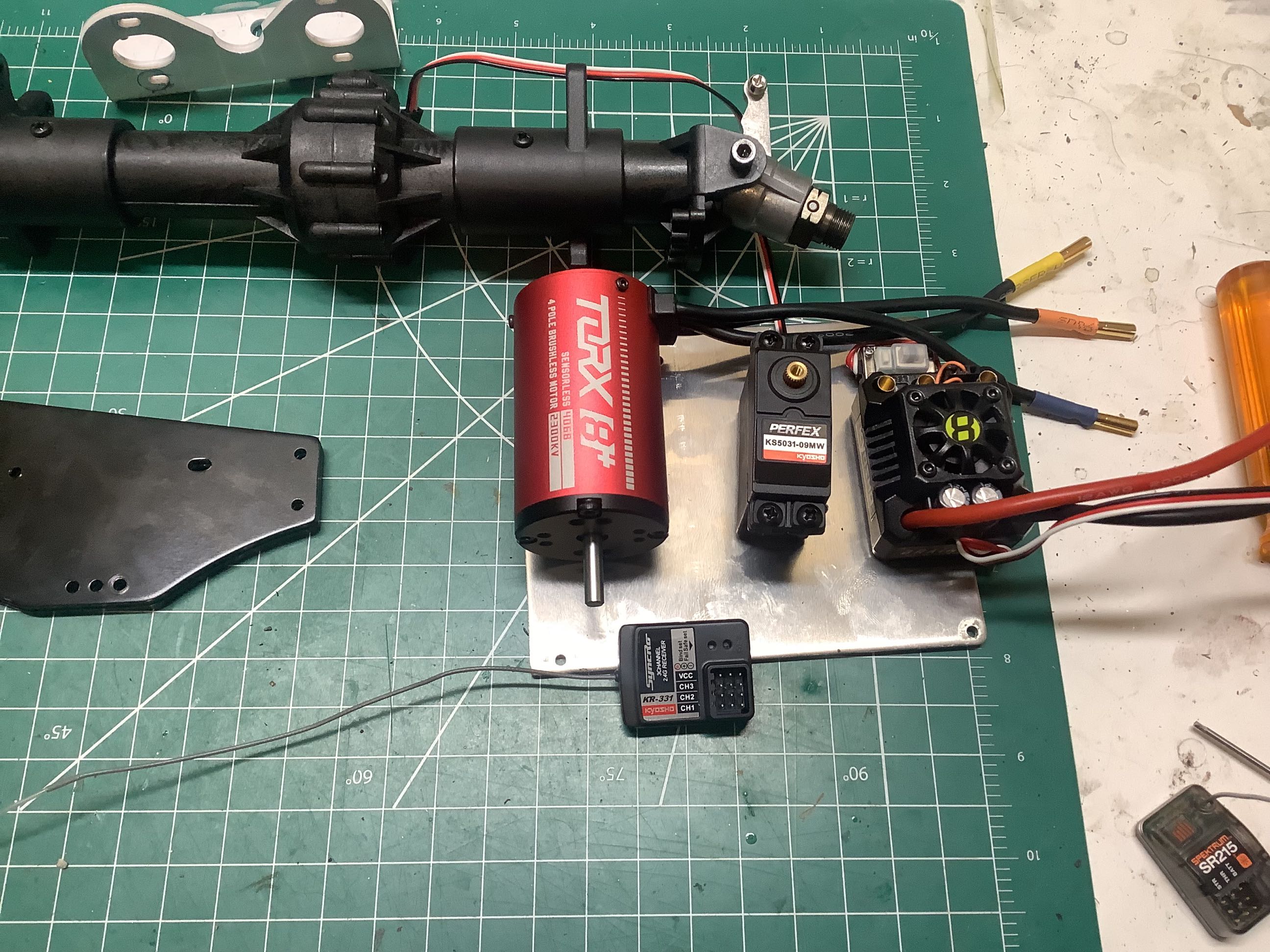
The suspension links are plastic while the panhard links are aluminum . The steel driveshafts are shown to the right. On the far right you can see the electronics package. The radio system is completely adequate, but I replaced the receiver with a Spektrum so I use my normal radio. The steering servo has a paltry 125 oz-in of torque which is pretty sad for a model of this size, but it seems to work OK. It does have metal gears and has proven durable so far. As far as I can tell, the clumsily named "Torx" motor and "Braniz" ESC are both rebranded Hobbywing items. The motor is an EZRun 4268 2300kV model which is actually slightly different than the one currently offered by Hobbywing (2600kV), but otherwise appears identical. The ESC appears to be an EZrun Max 10 SCT. Note that this is a 10th scale ESC paired with an 8th scale motor, but it is rated for motors up to 3000kV at 4s, so it should be fine.
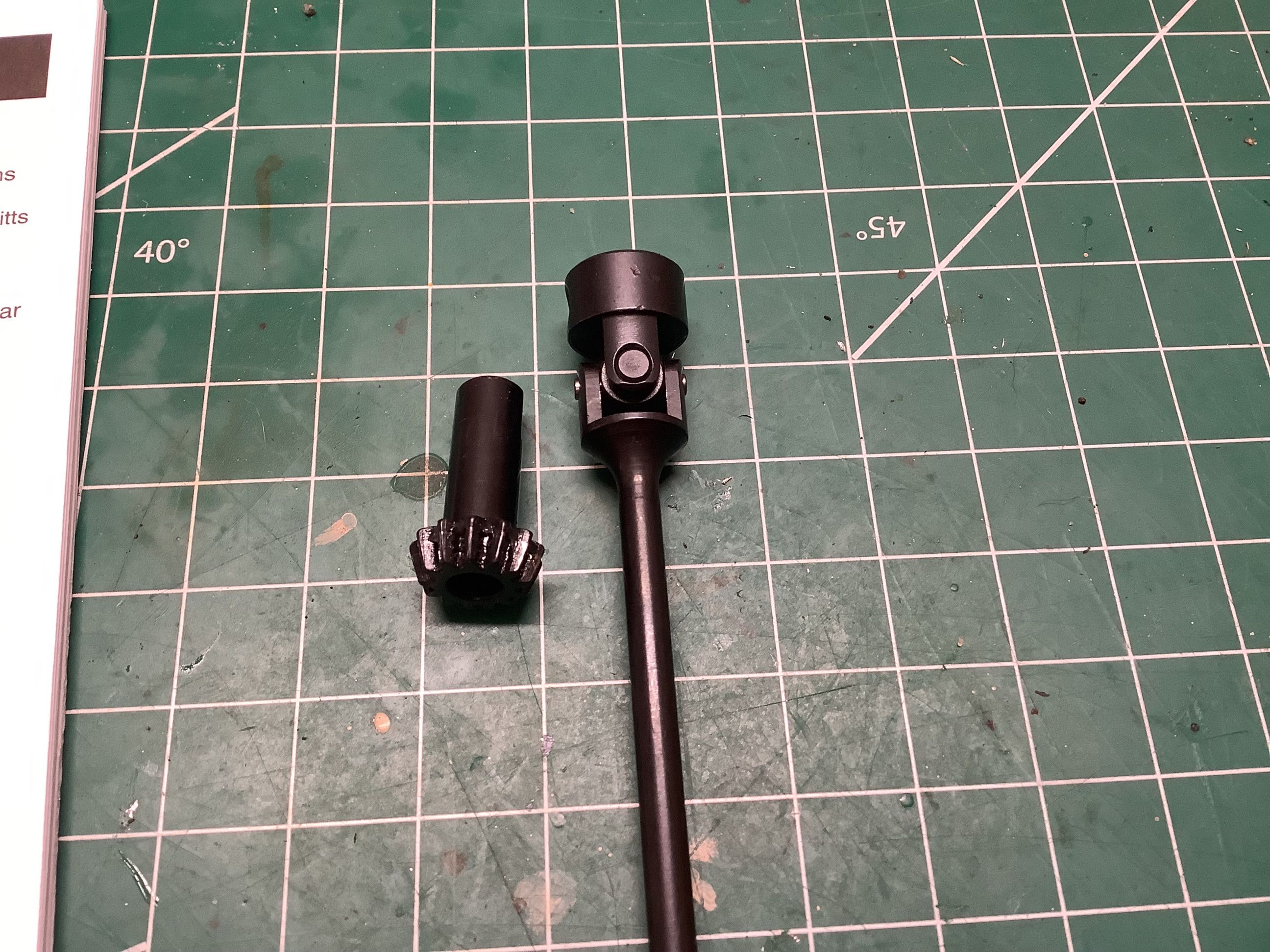
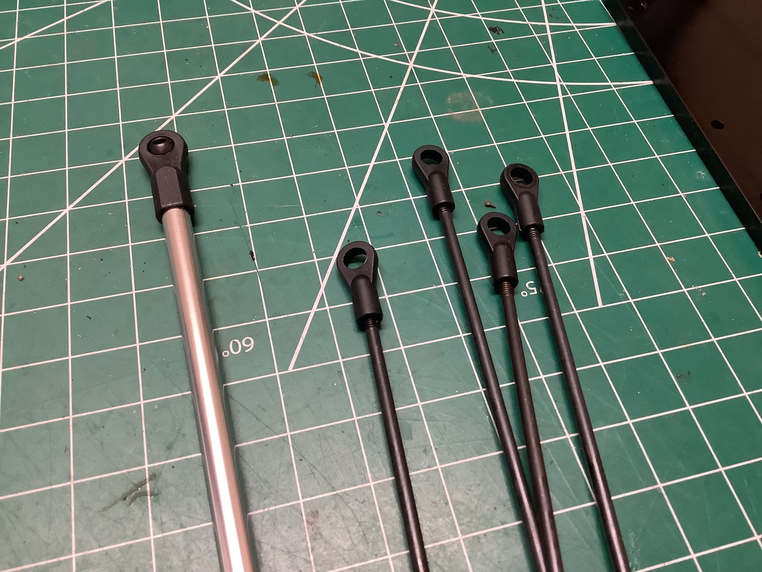
Here are a couple of oddities of part sizing. The shaft on the pinion for the differentials is a massive 8mm in diameter and made of steel. Great! But the drive shaft which feeds it (and carries exactly the same torque) is only 5mm. That's a 2.5x difference in strength for mating parts. Why? On the right you can see a similar issue on the rods. The panhard bars are 6mm in diameter while the steering links are 3mm. 3mm is really small for a model with massive tires like these. They seem like the weakest part of the design. With that being said, the steering servo hardly carries any torque anyway.
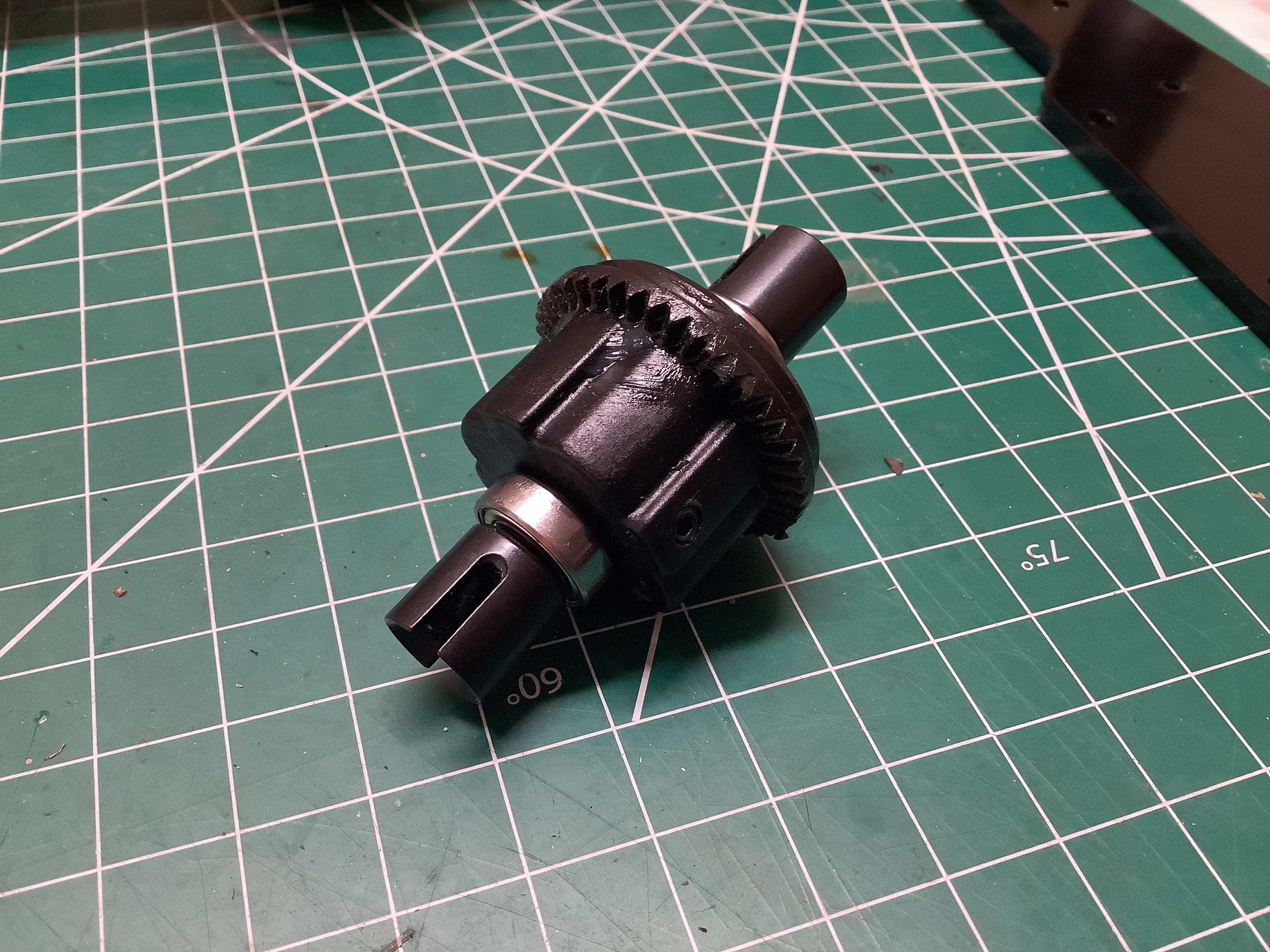
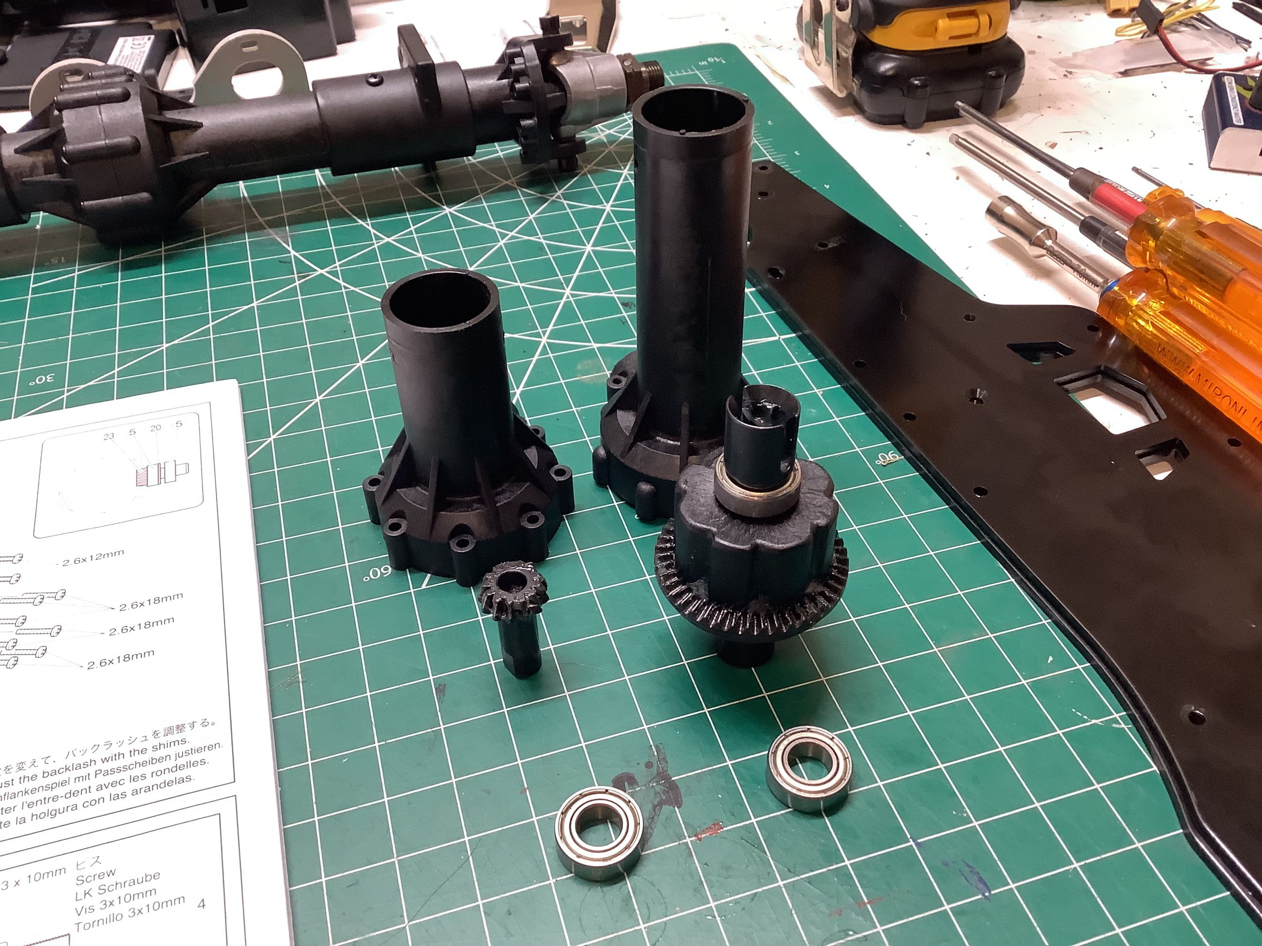
I didn't open up the differential but according to the manual it uses 4 steel spider gears and 3000wt silicone oil. The drive cups are supporting by massive 8x15mm ball bearings so they should be plenty strong. The picture on the right shows the parts needed to support the differential, ring, and pinion into the axle housing. The axle diameter is much larger than the parts inside it, so it is mostly empty space. Still, that diameter gives it a lot of bending stiffness. The real USA-1 used axles from a 5-ton, so I'm OK with it.

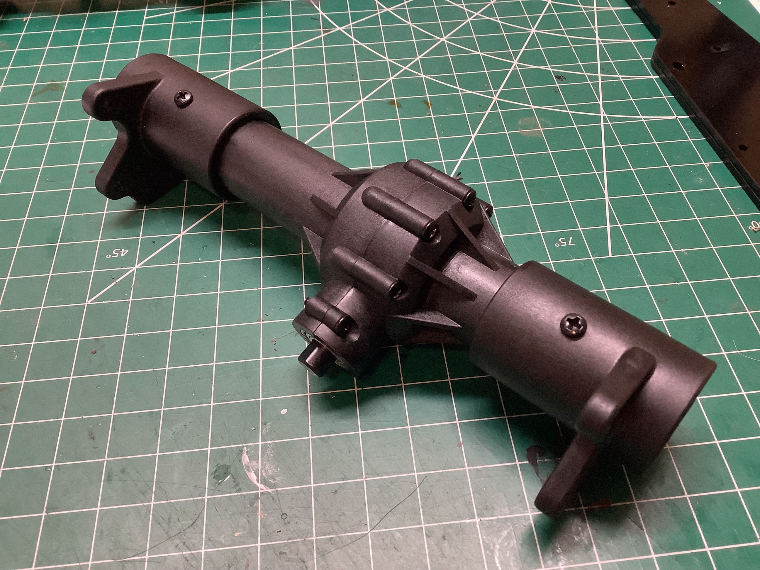
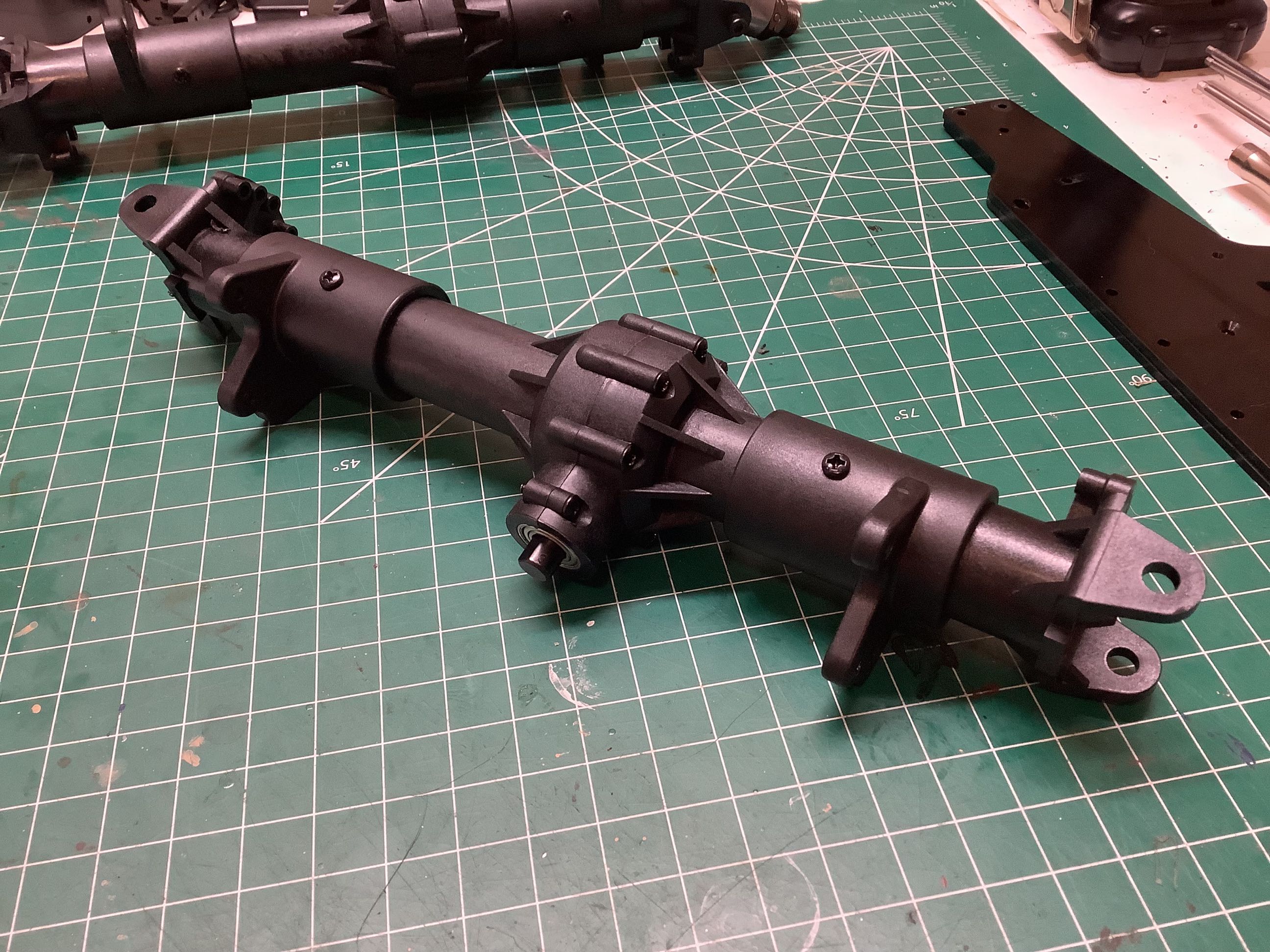
On the left you can see the central part of the axle housing buttoned up. On the right I've added the extension tubes which form the suspension mounts. Note that the differential is off center.
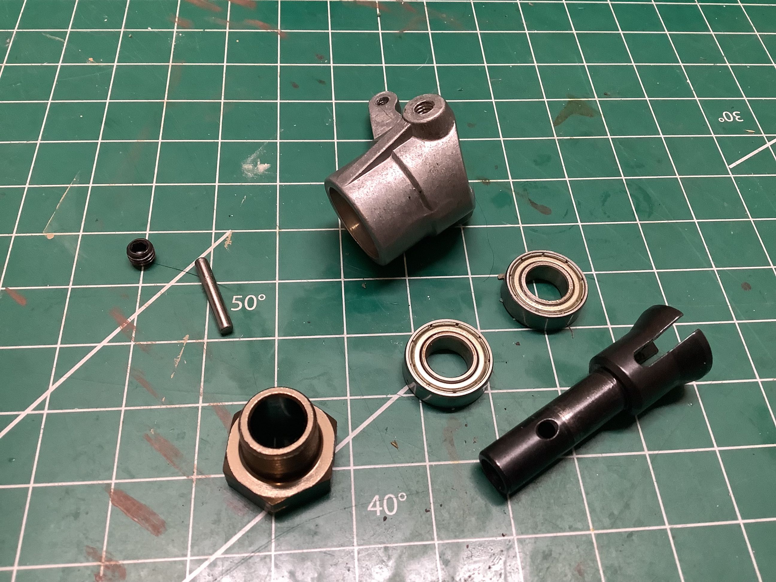
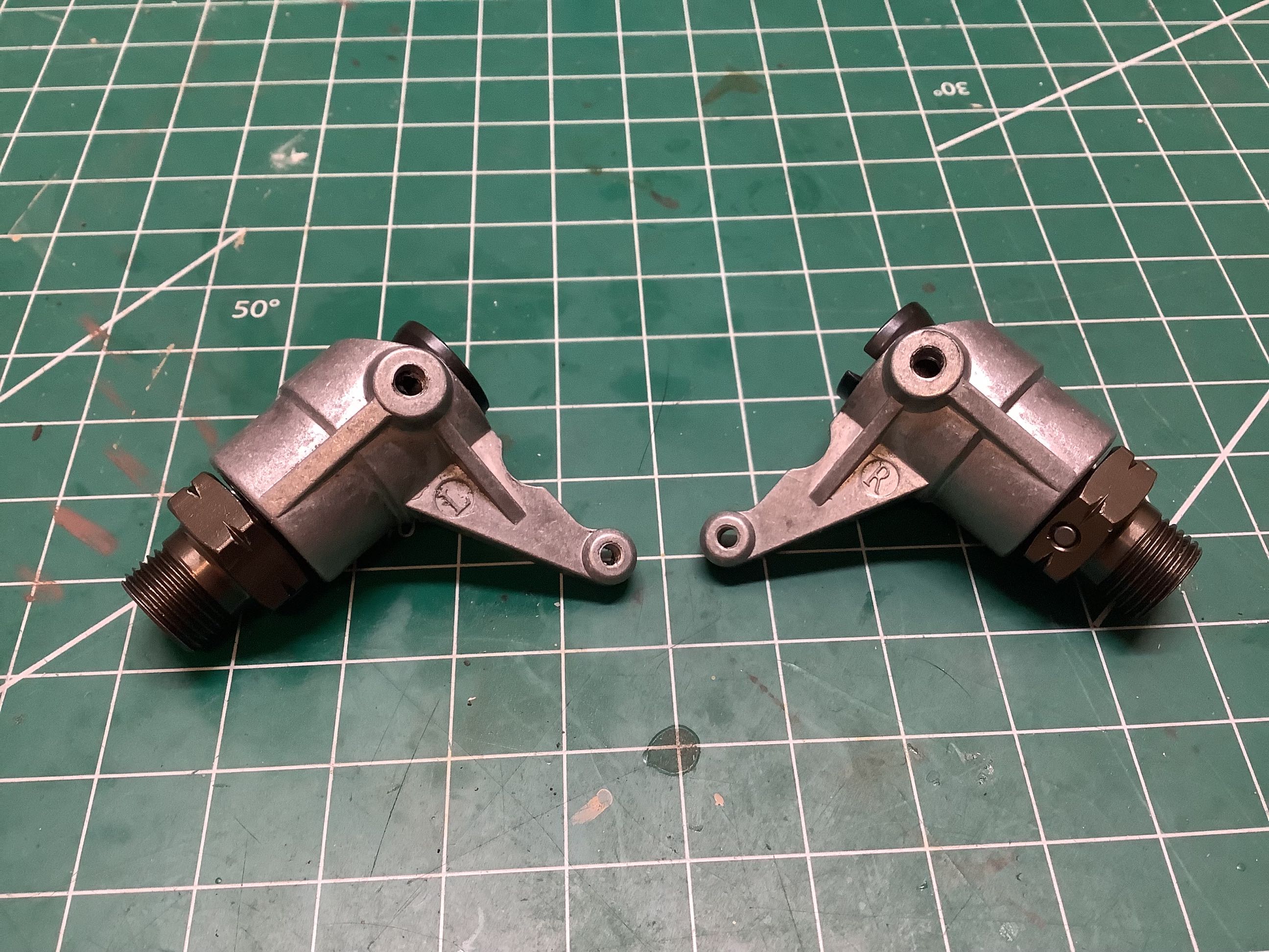
The steering knuckles are cast aluminum and use dual 8x16mm bearings. The hexes are 17mm. An exploded view is shown on the left. The right hand image shows the completed assemblies which you can see are labelled L and R.
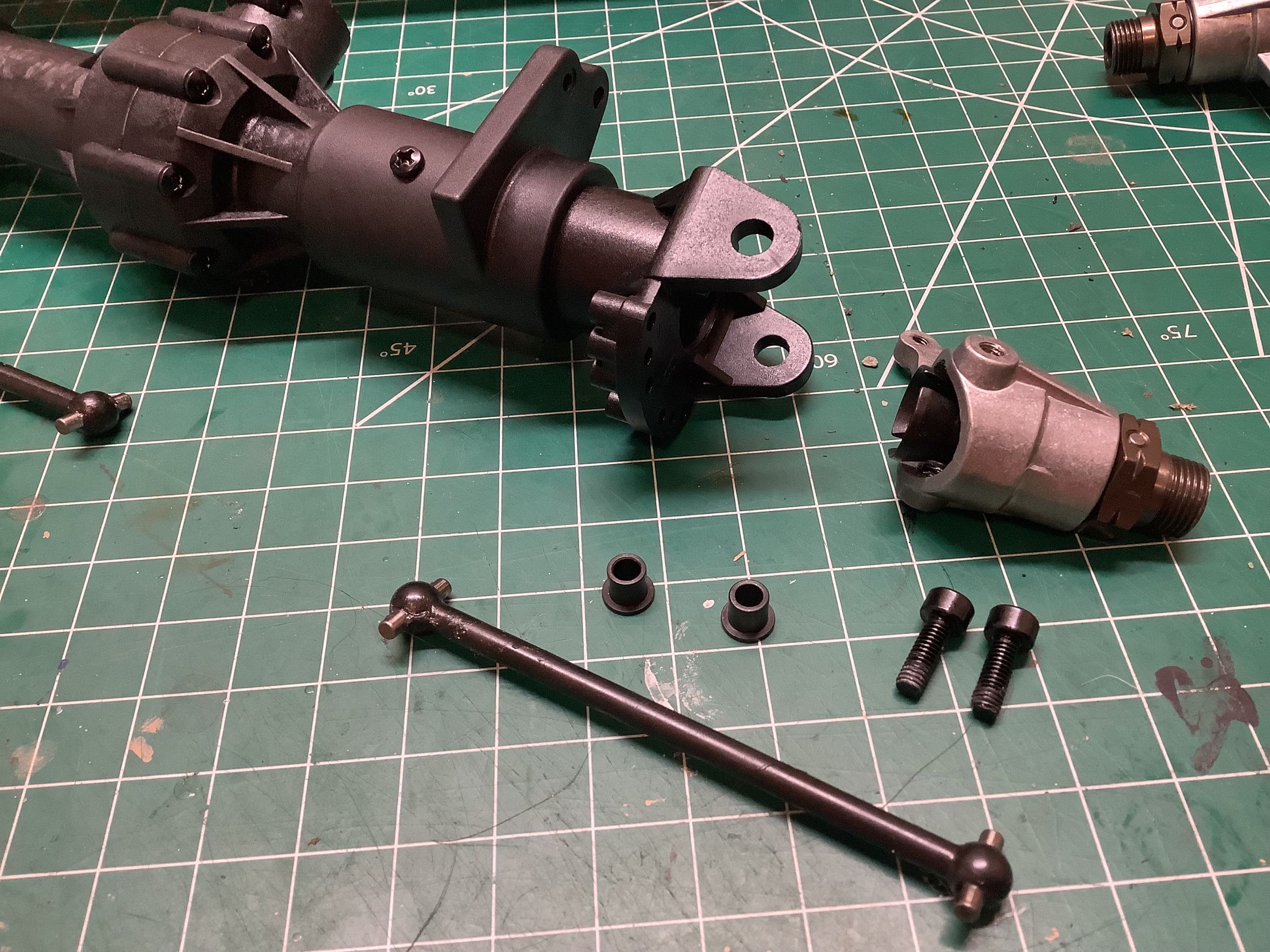
Now the steering supports can be installed as shown on the left. The axle itself is a dogbone style. I would have preferred universals here. The steering knuckles are supported within the supports using a set of steel flanged bushings.
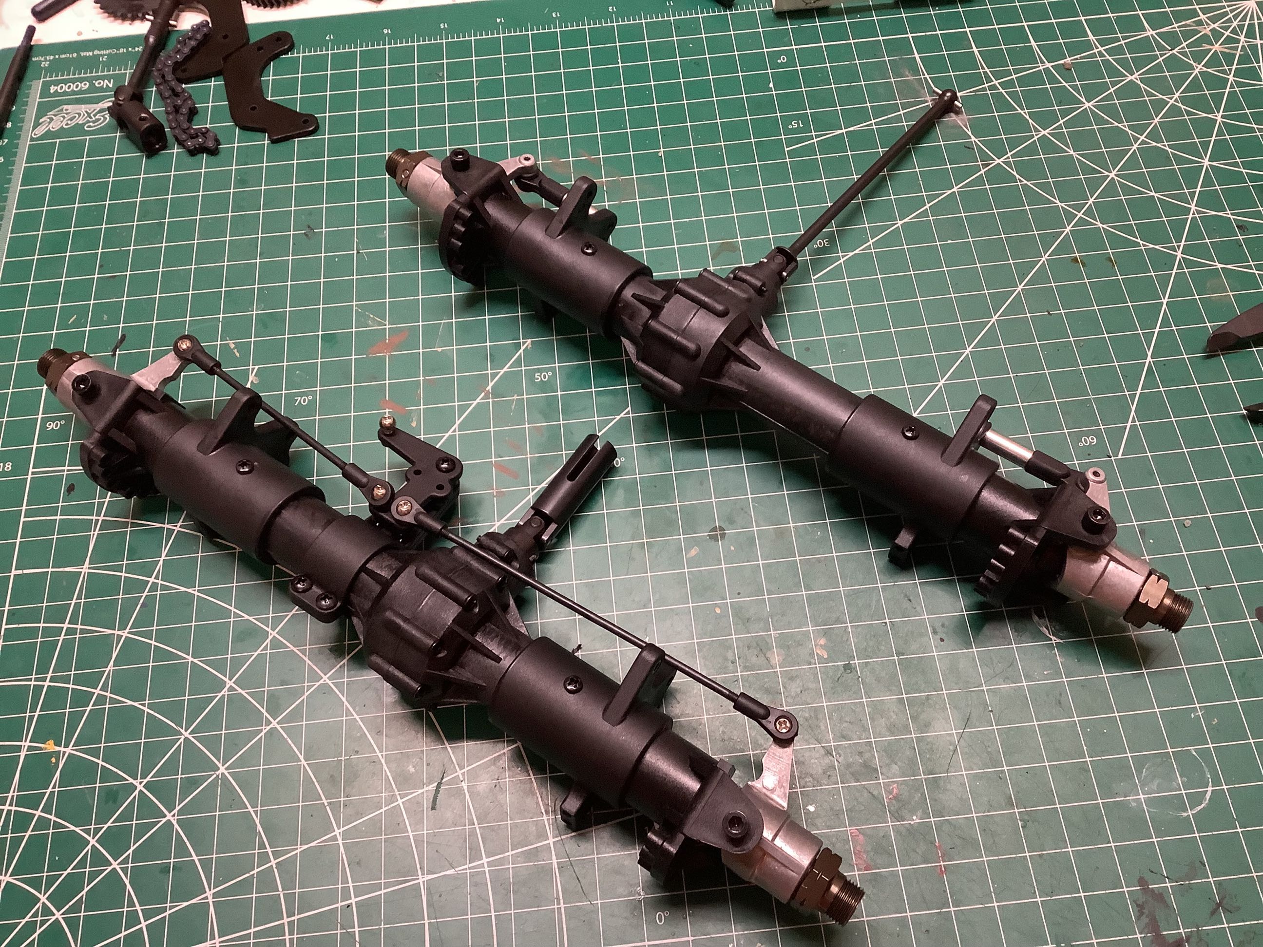
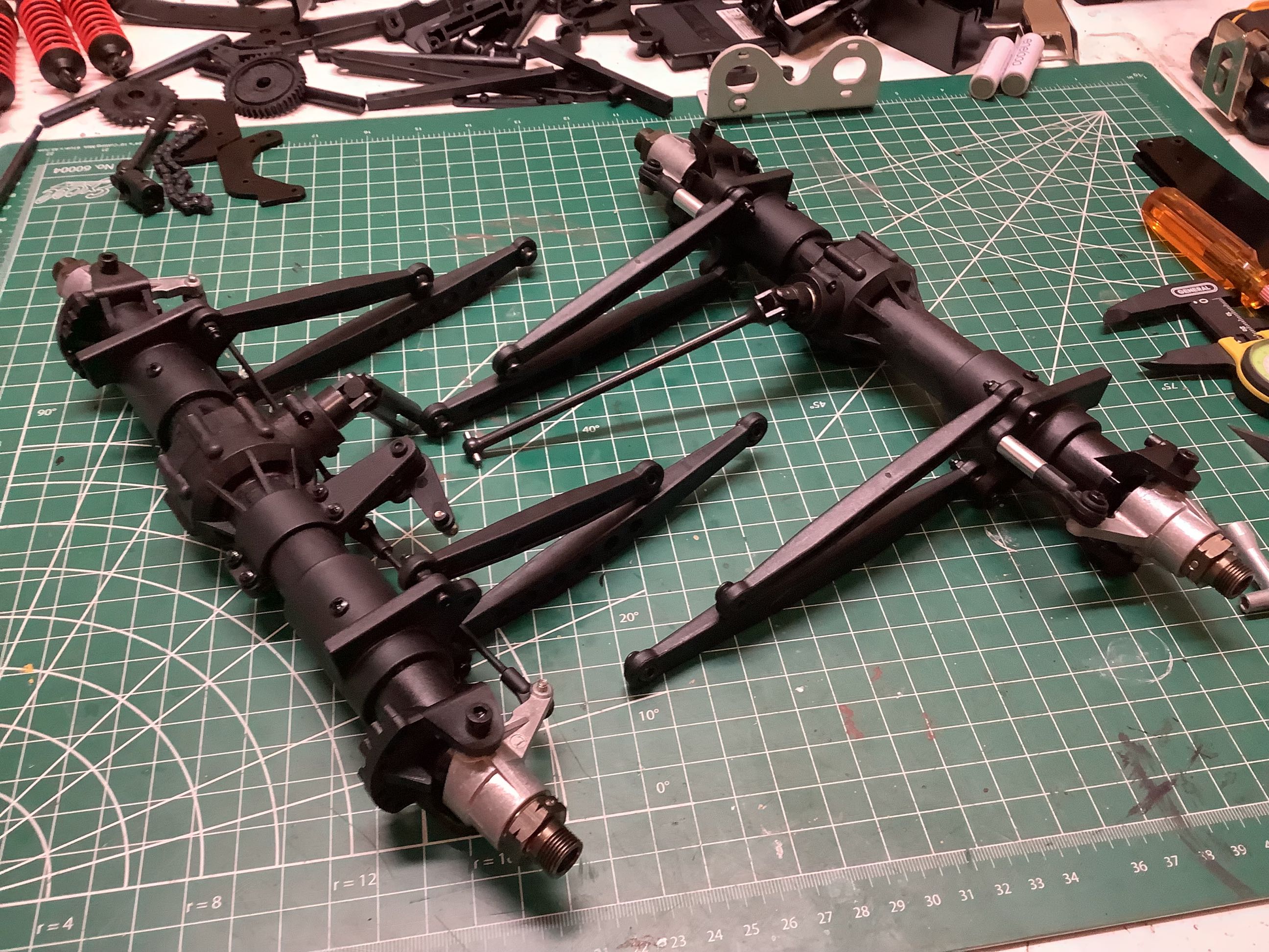
Now the front and rear axles are complete. Note that both support steering, though only the front axle is equipped for it out of the box. The rear axle uses a set of short links to lock the steering angle. The front axle has a bell crank mounted the housing which means two steering links are needed. Note that the rear drive shaft is fixed length while the front uses a sliding joint. Why? Perhaps because this model does wheelies so the front axle sees full extension and compression regularly and needs more travel. Just a guess. With the axles oriented toward each other as shown on the right, you can see that both differentials are offset toward the right of the vehicle.
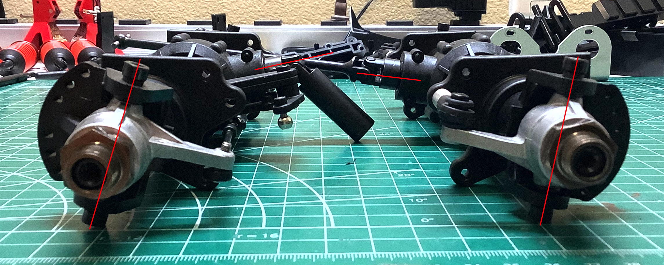
It may appear at first that the front and rear axles are identical, but they are not. If they were the same, the huge caster angle of the front axle would be mirrored on the back which would make the rear wheels almost impossible to keep stable (if connected to steering) like the Clodbuster. Caster angle tends to keep the wheels facing forward when rolling, but if it is reversed the wheels will always want to turn. Instead, the rear axle is set up so there will be no caster at all once the axle is installed (the kingpin will be vertical). You can also see that the angle at which the drive shaft departs the differential is different between front and rear.
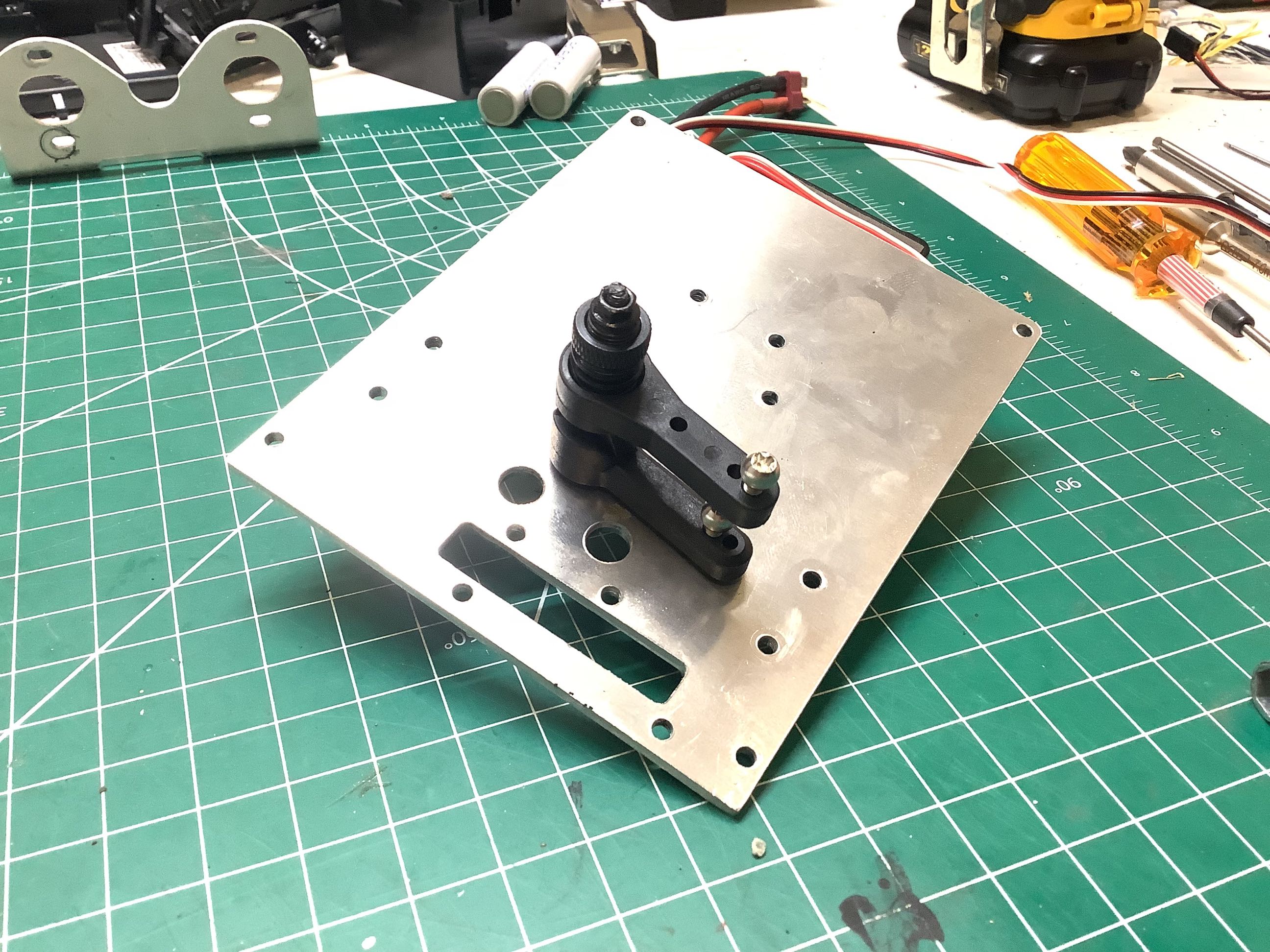
This model has a steering system like nothing I've ever seen before, although it shares certain similarities with the Clodbuster. The single steering servo is centrally mounted and drives an input bellcrank. Between the input and output cranks is a servo saver. To enable rear steering, you just add another ball joint to the output crank and install steering rods to the rear. Since front and rear use the same crank, there is no way to turn the rear steer on and off if you decide to go with this option.
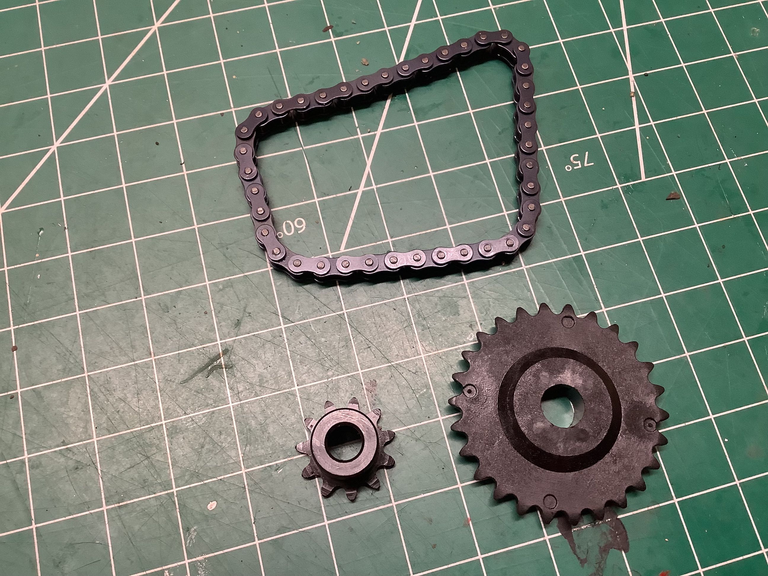
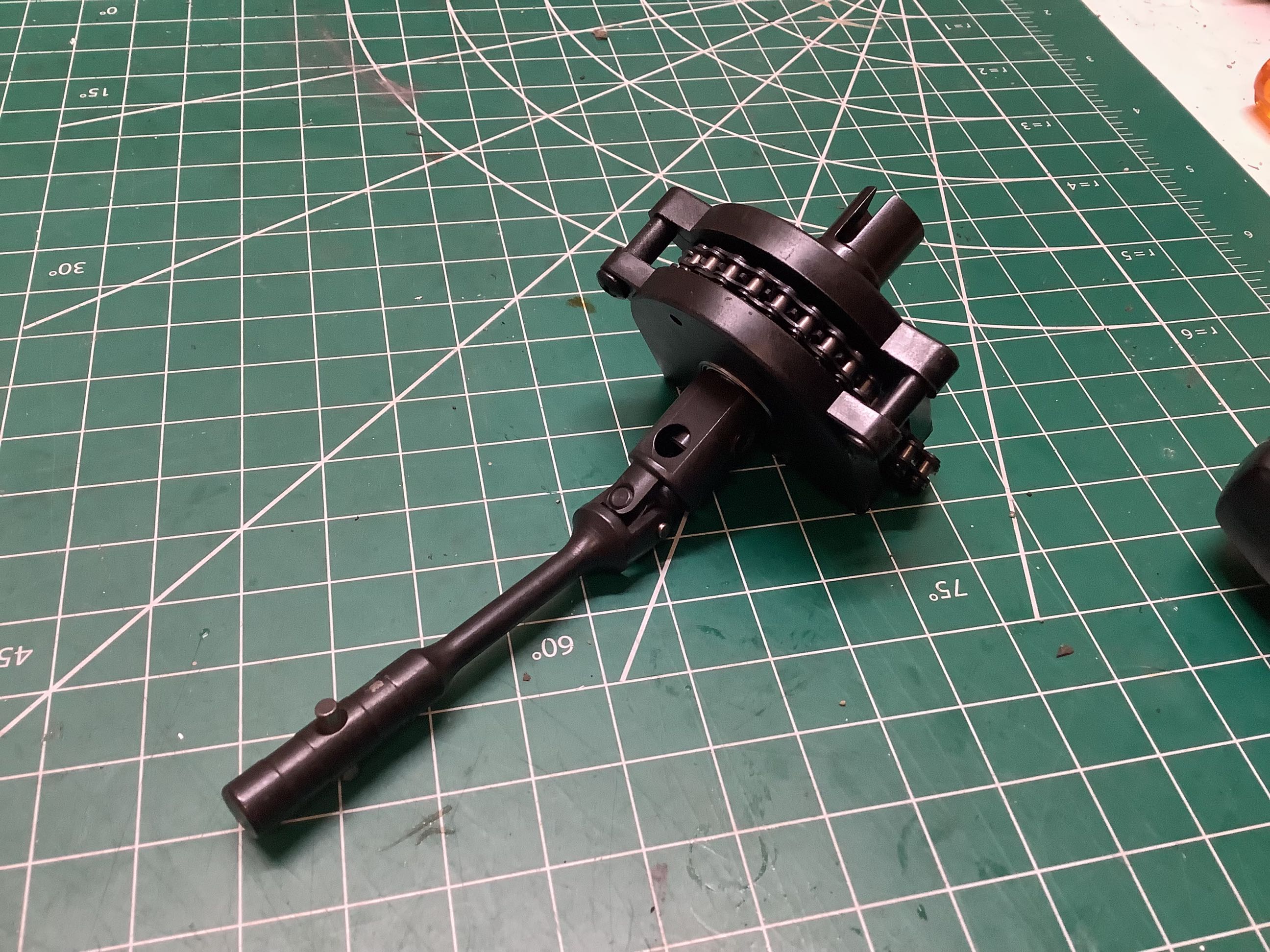
I've never seen a chain drive monster truck before. I haven't run the numbers, but it certainly seems like this chain would be the weak point in the drivetrain. The drive sprocket has 11 teeth while the follower has 26 so there is a 2.36:1 reduction here. The picture on the right shows the follower sprocket attached to the drive shafts.
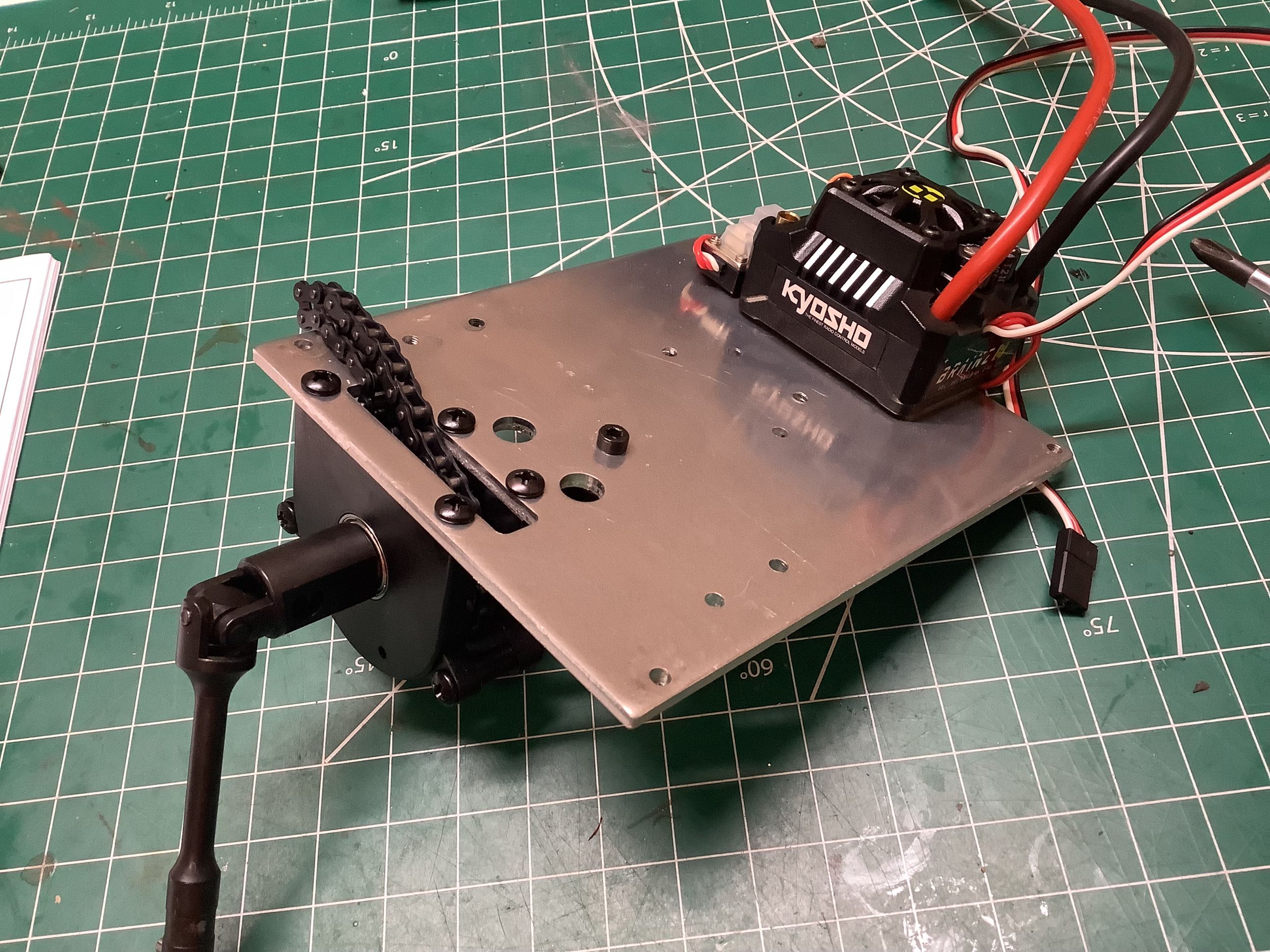
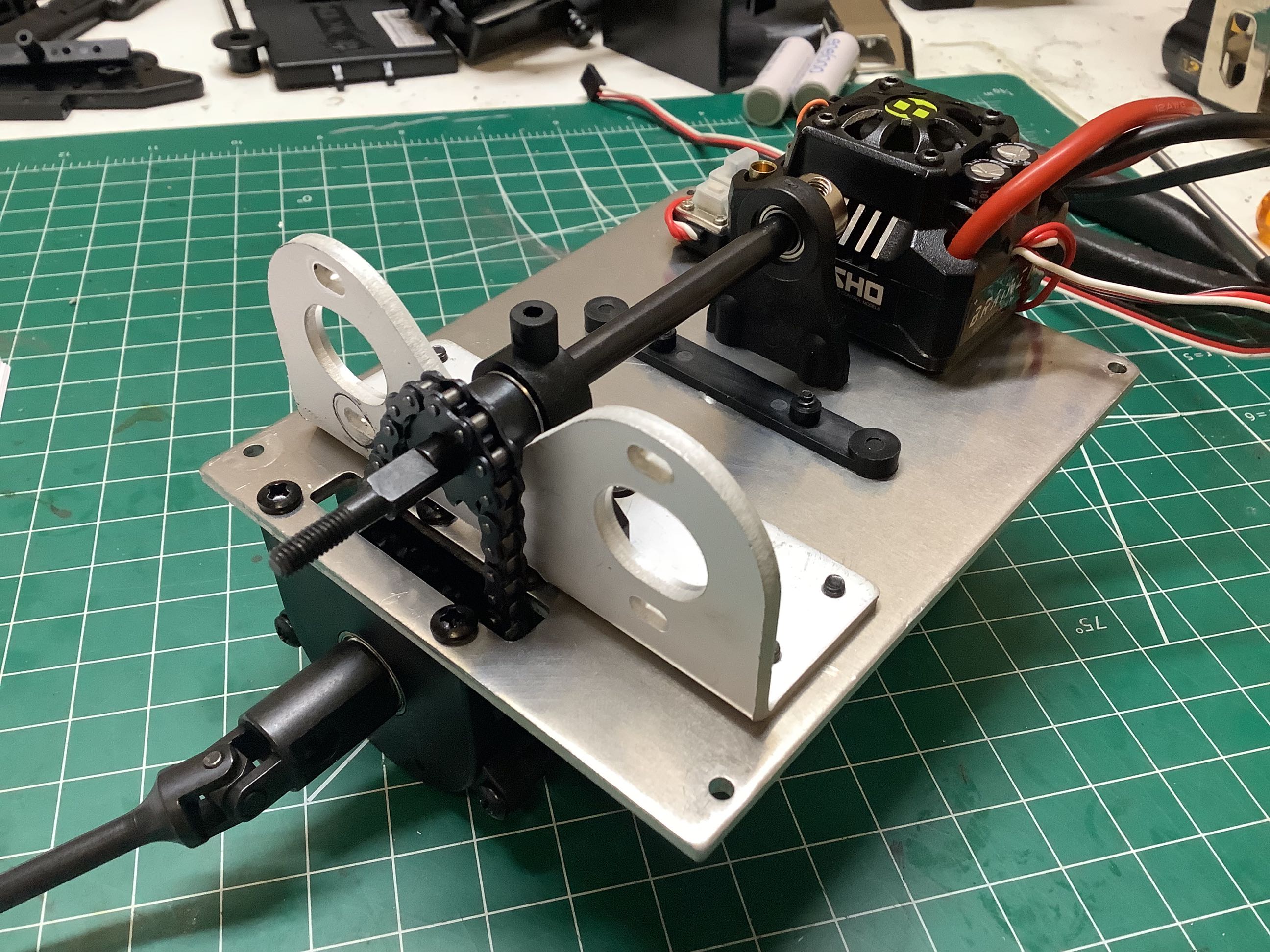
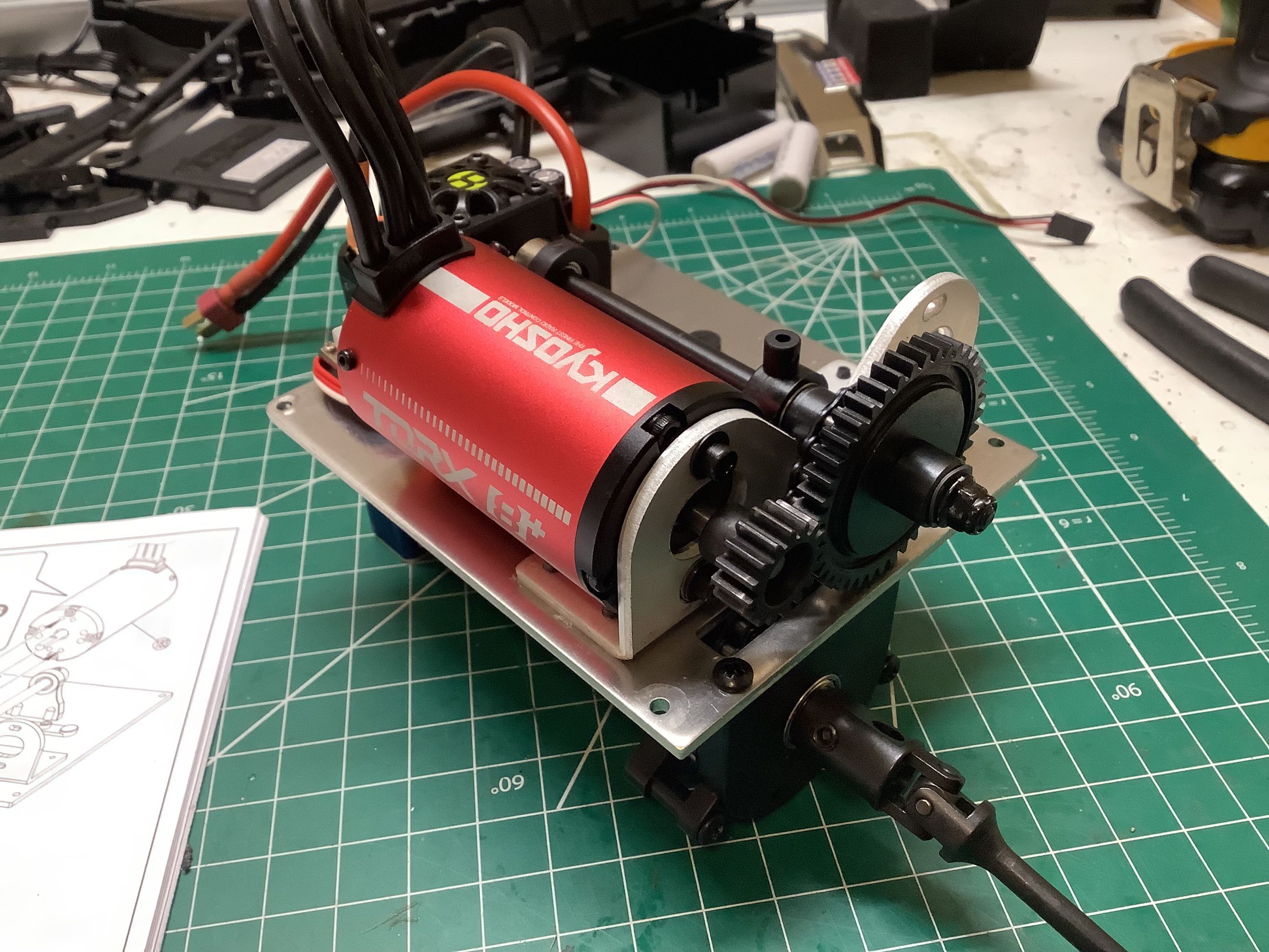
Here the chain assembly is attached to the central chassis brace and passed through a slot. This brace also serves as the electronics tray. On the right I've added the upper sprocket which is attached to a shaft supported by a pair of pillow blocks. You'll also see that there are two motor mounts which means this model can support twin motors. Only a madman would ever do that with a brushless system (like my TXT-2), but I could see using a pair of brushed motors.
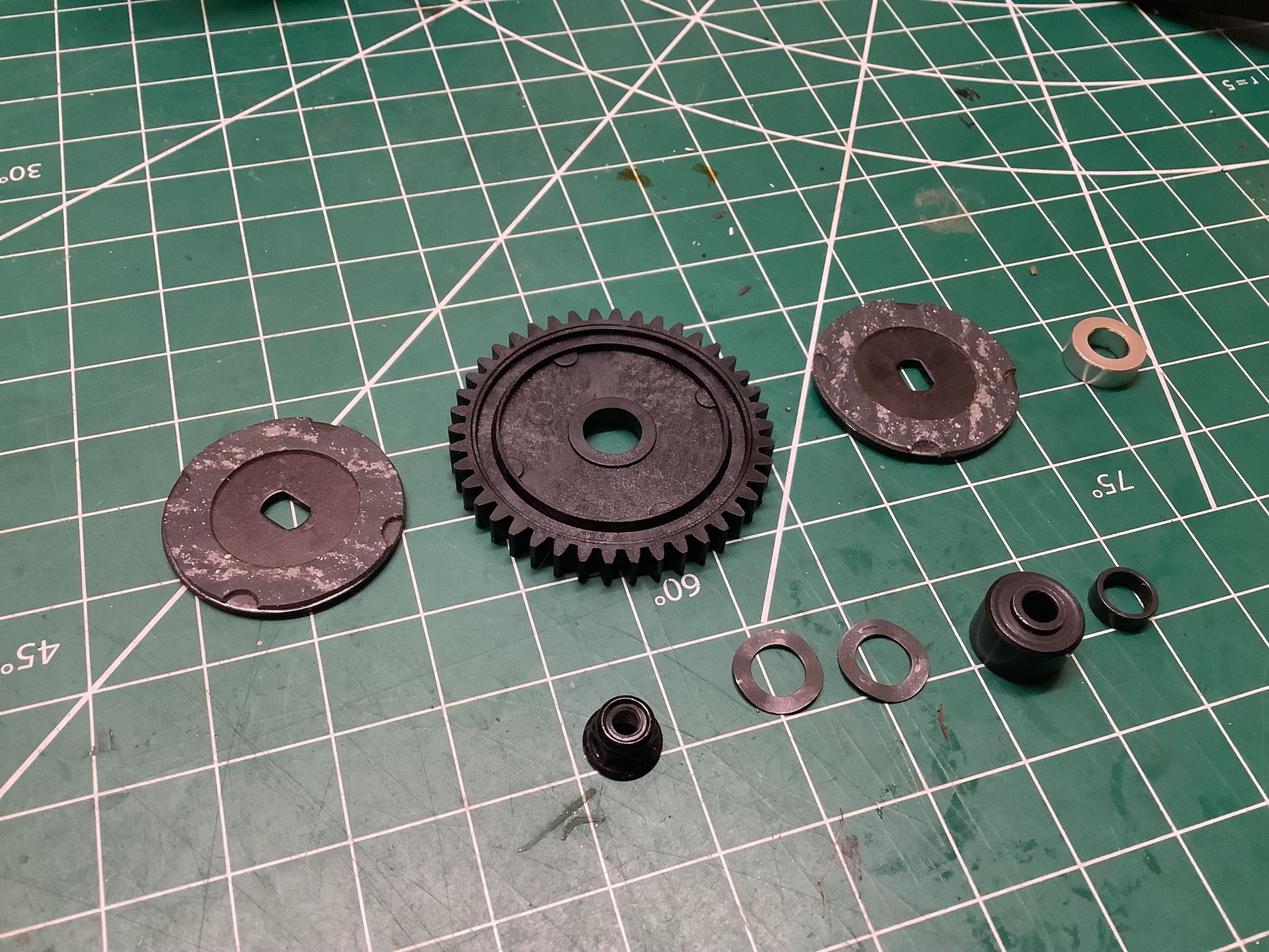
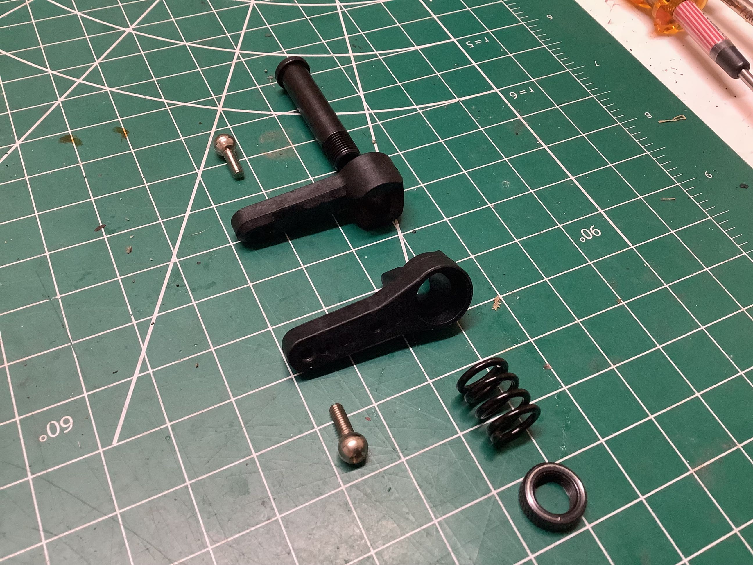
This is a very odd slipper clutch because it is not adjustable. You tighten the nut down firmly. It works because the metal bushing (lower right) is slightly thicker than the spur gear it fits into which means you are clamping across the bushing, not across the friction surfaces. This results in a fixed amount of clamping force based completely on geometry.
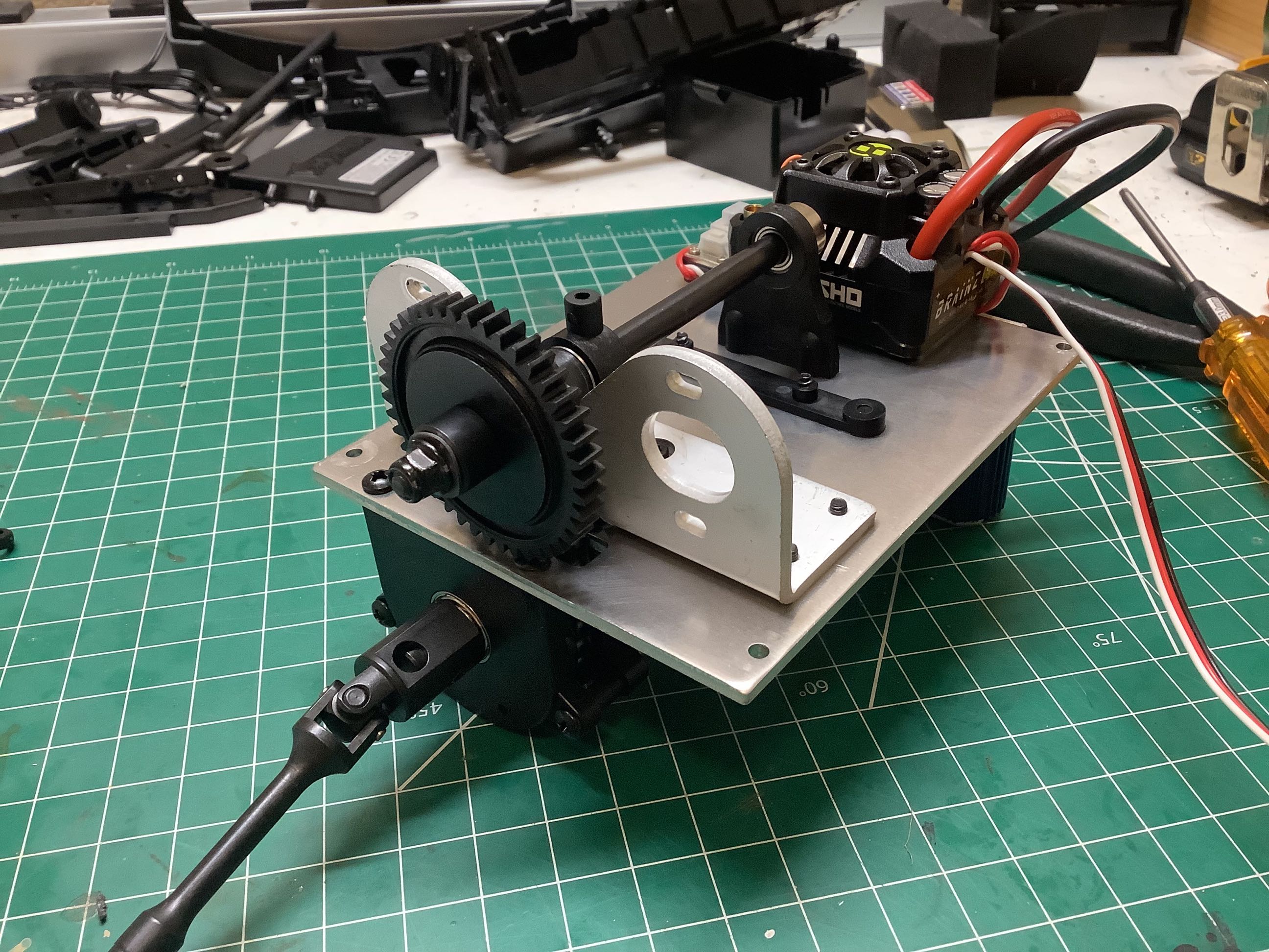
The 1.0 mod steel pinion gear has 16 teeth while the plastic spur has 42 so that's a 2.63:1 reduction. Combined with the chain reduction of 2.36:1 and the ring/pinion reduction of 3.31:1, that's an overall reduction of 20.5:1.
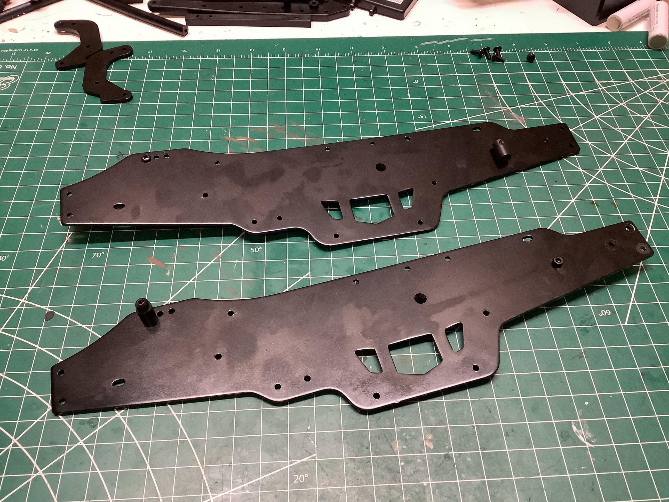
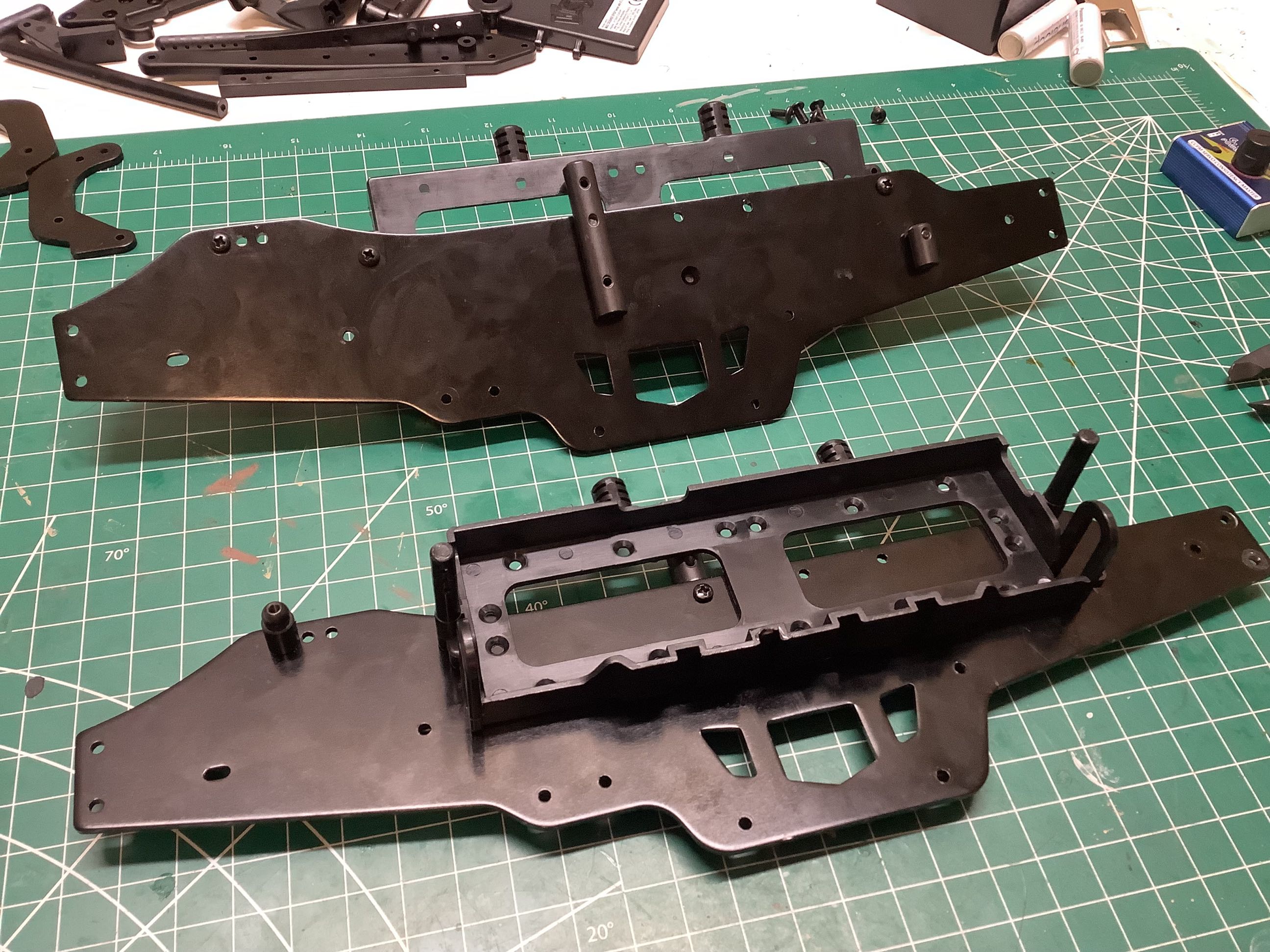
This is a Twin Vertical Plate chassis like the old HPI Savage monster trucks. These aluminum plates ensure that there is going to be essentially no longitudinal bending. The twin battery boxes attach directly to the plates as shown. These battery boxes have adjustable covers that allow the use of very thick batteries if desired.
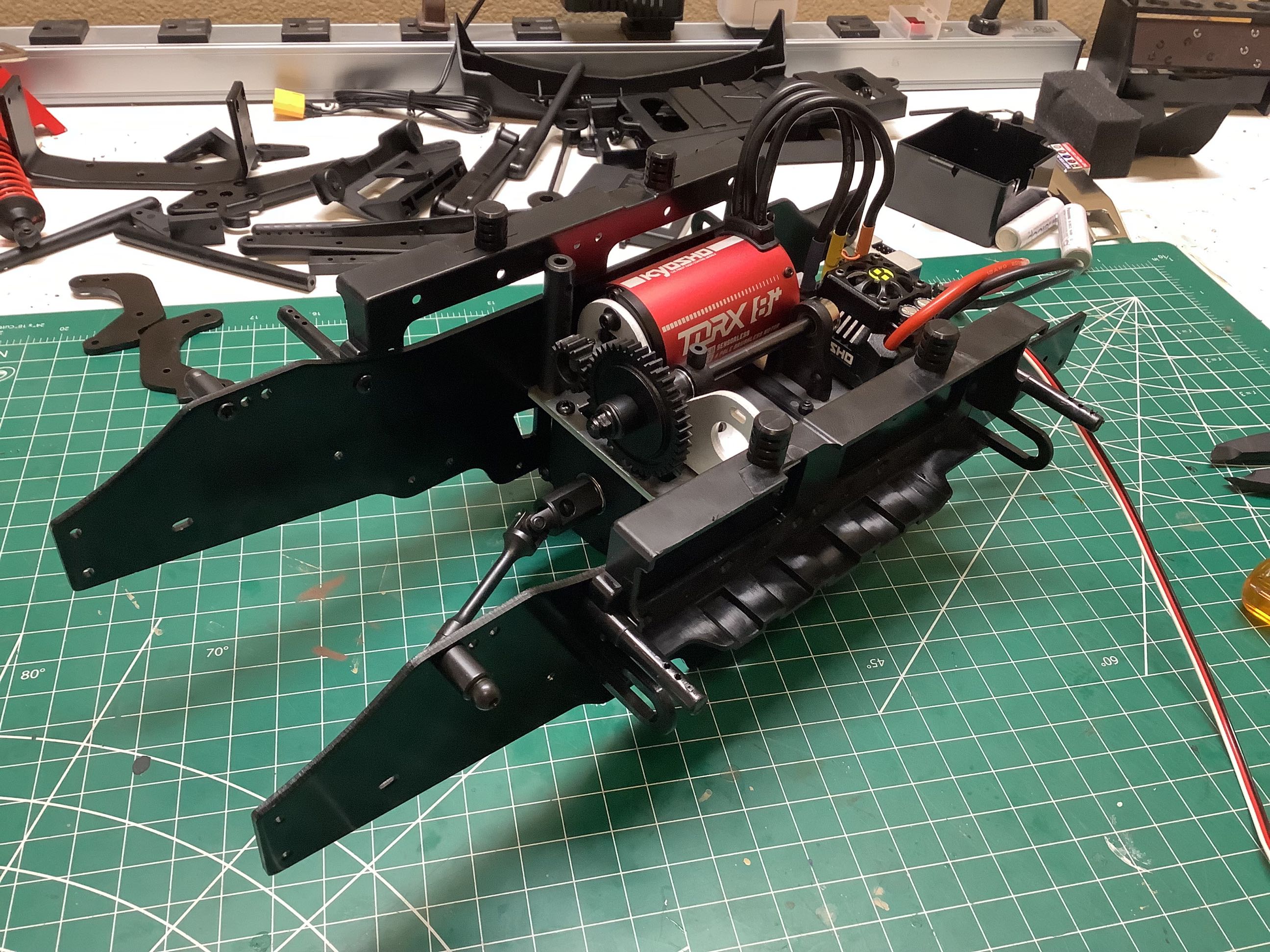
Here the central transmission assembly has been used to join the two chassis plates. The method of attaching the transmission is, in my opinion, pretty weak. They use giant steel standoffs, but with only one fastener per part.
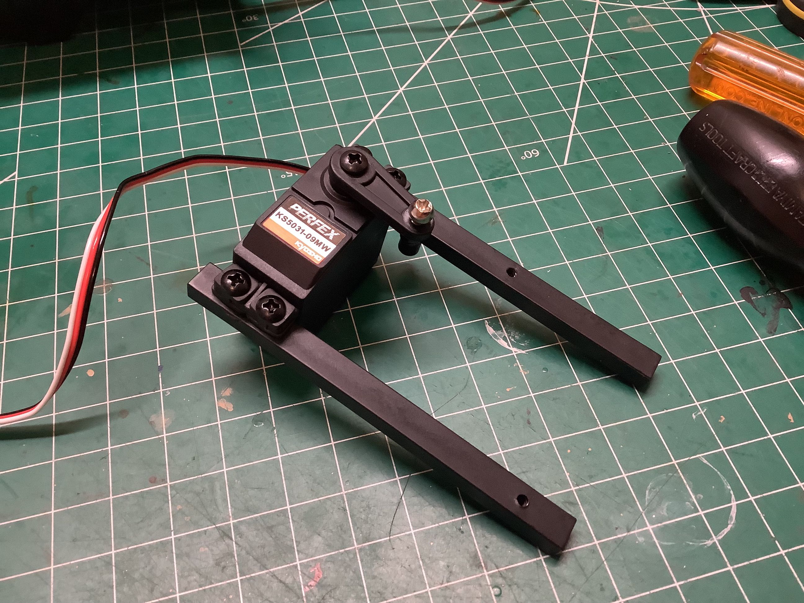
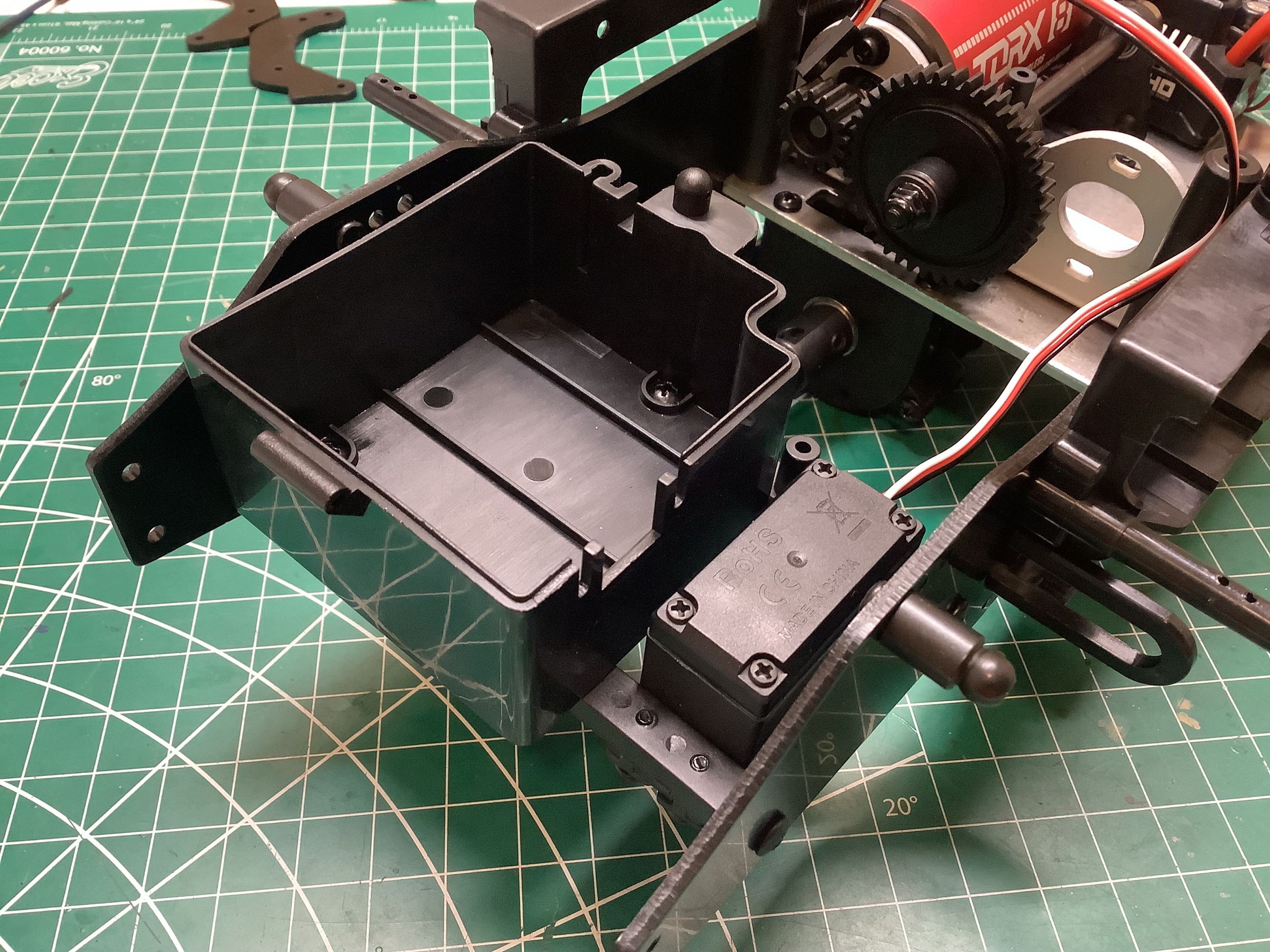
These two cross members support both the steering servo and the massive radio box. You may wonder at the need for such a large box, but keep in mind that this model is also available in nitro in which case this box would also contain a receiver battery box. Those big steel ball joints you see sticking out the sides of the chassis plates are for the shocks.
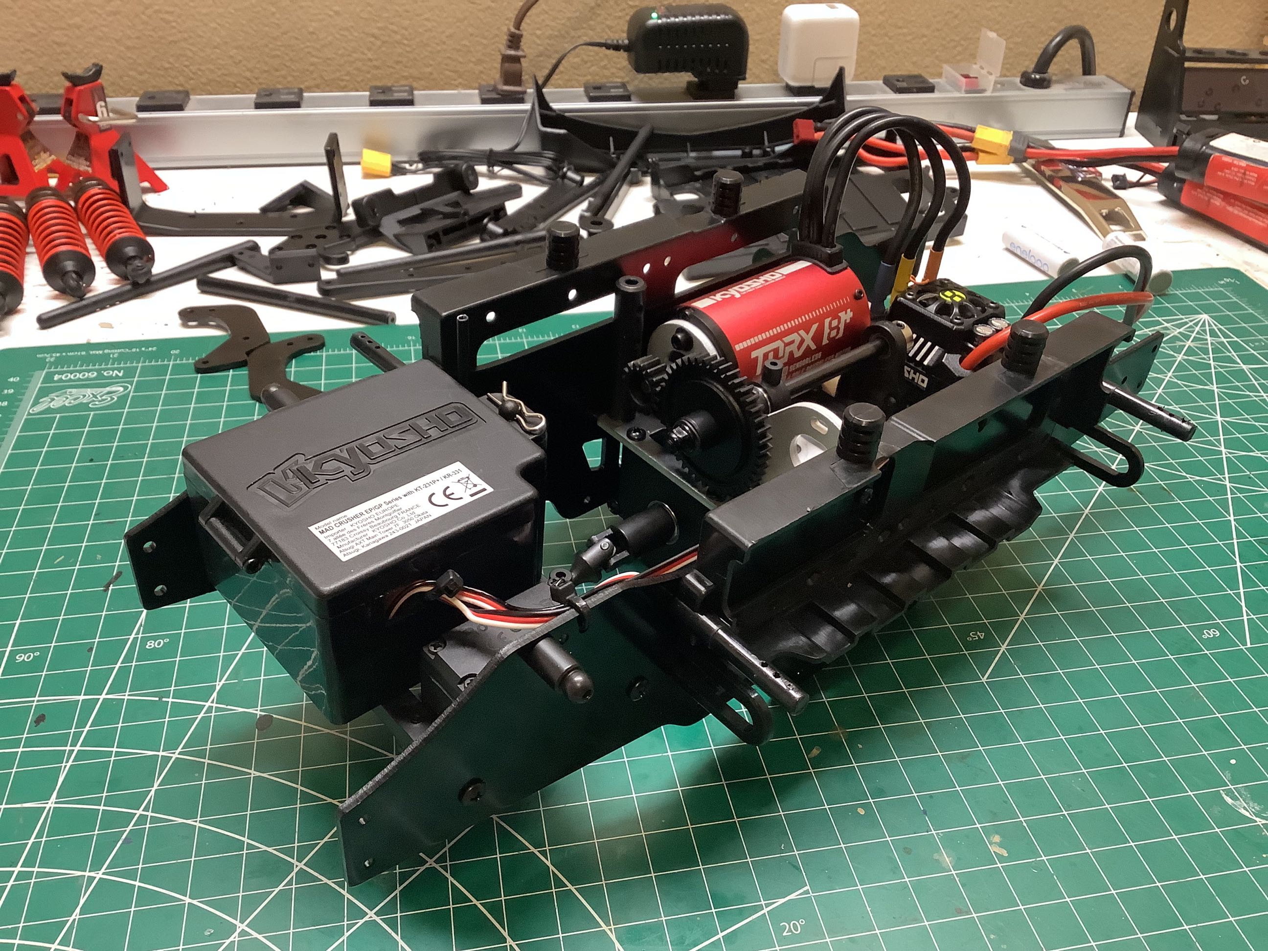
Here I've completed the installation of the electronics and closed up the radio box. At this point I can install batteries and make sure everything works.
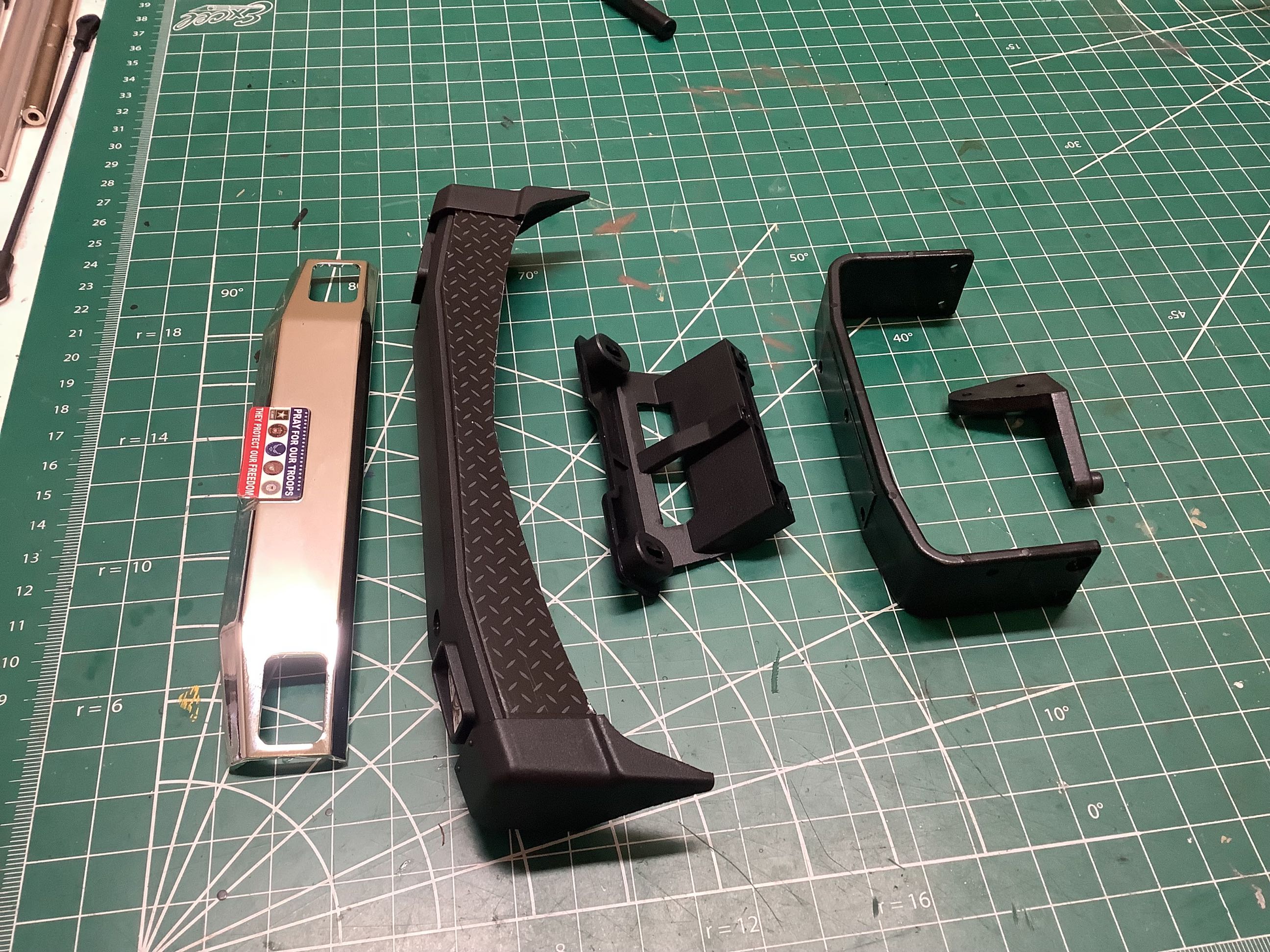
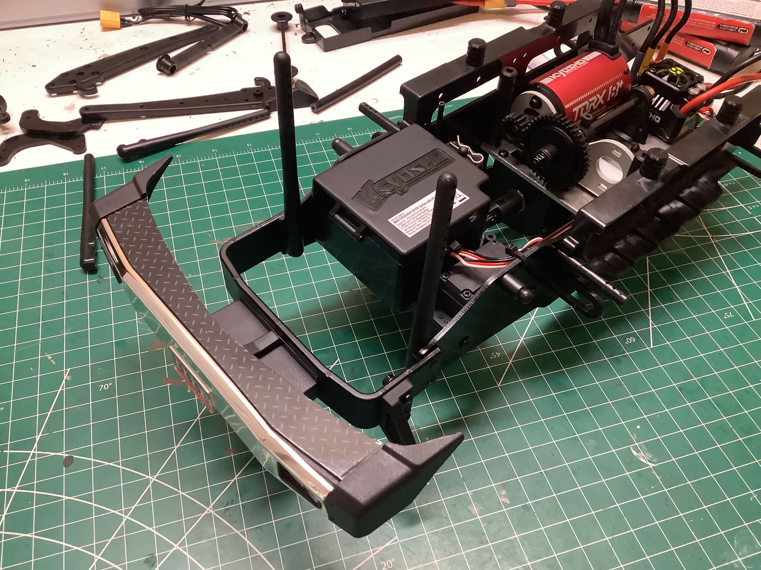
The front bumper is installed directly to a chassis cross member making it very strong. You can also see that I've installed the front body posts at this point.
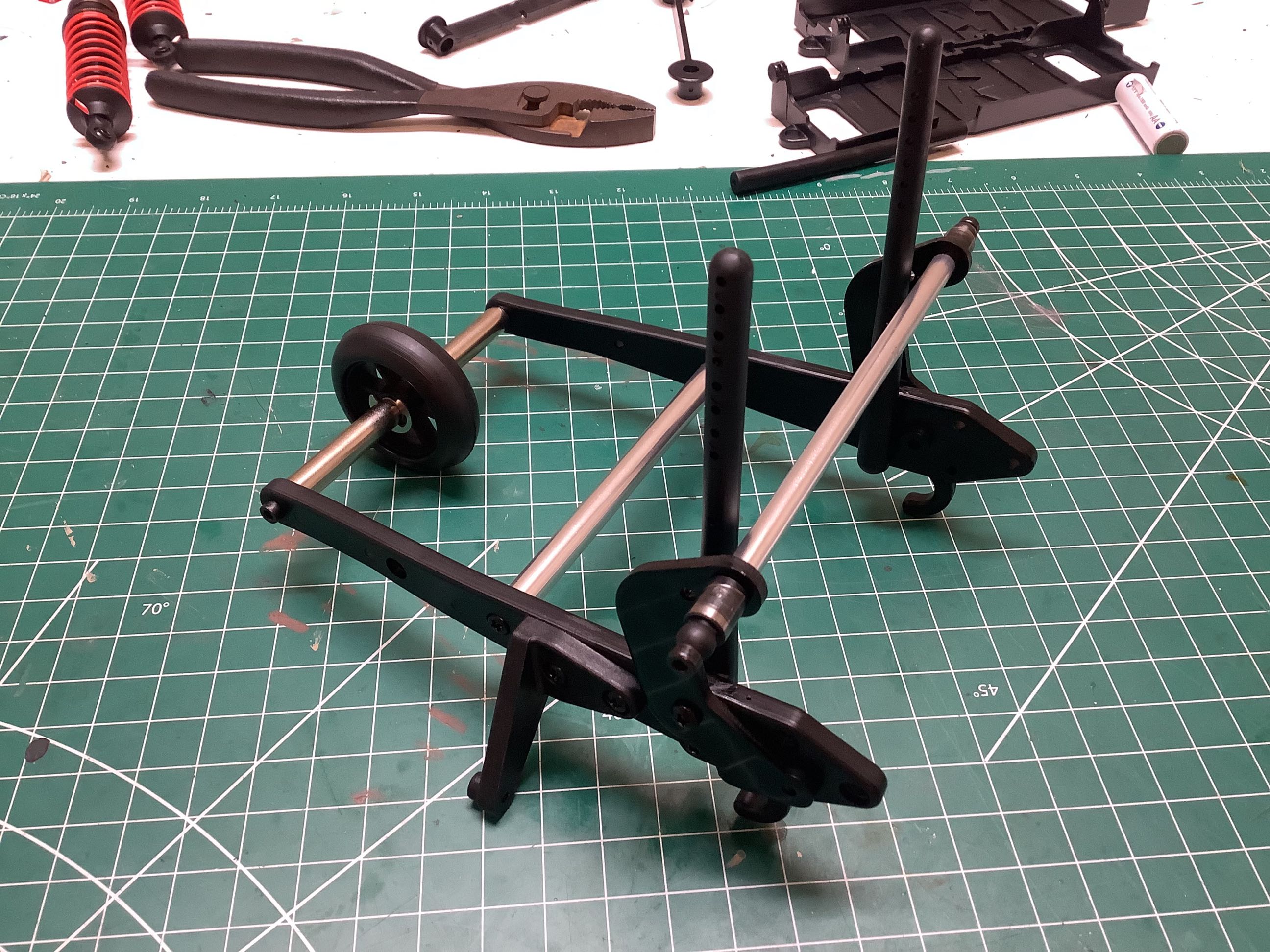
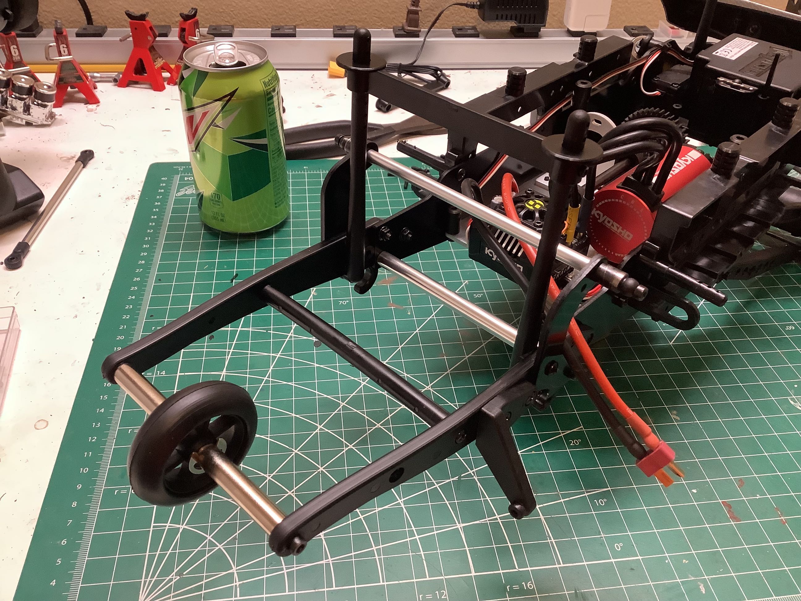
There is no structural rear bumper, instead the wheelie bar serves and both the rear cross member and bumper. The rear shock mounts are also extended behind the chassis plates with those wheelie bar brackets. Though it is not evident from this picture, there is a big problem with the wheelie bar. That nice big wheel on ball bearing cannot actually turn because the body rubs on it.
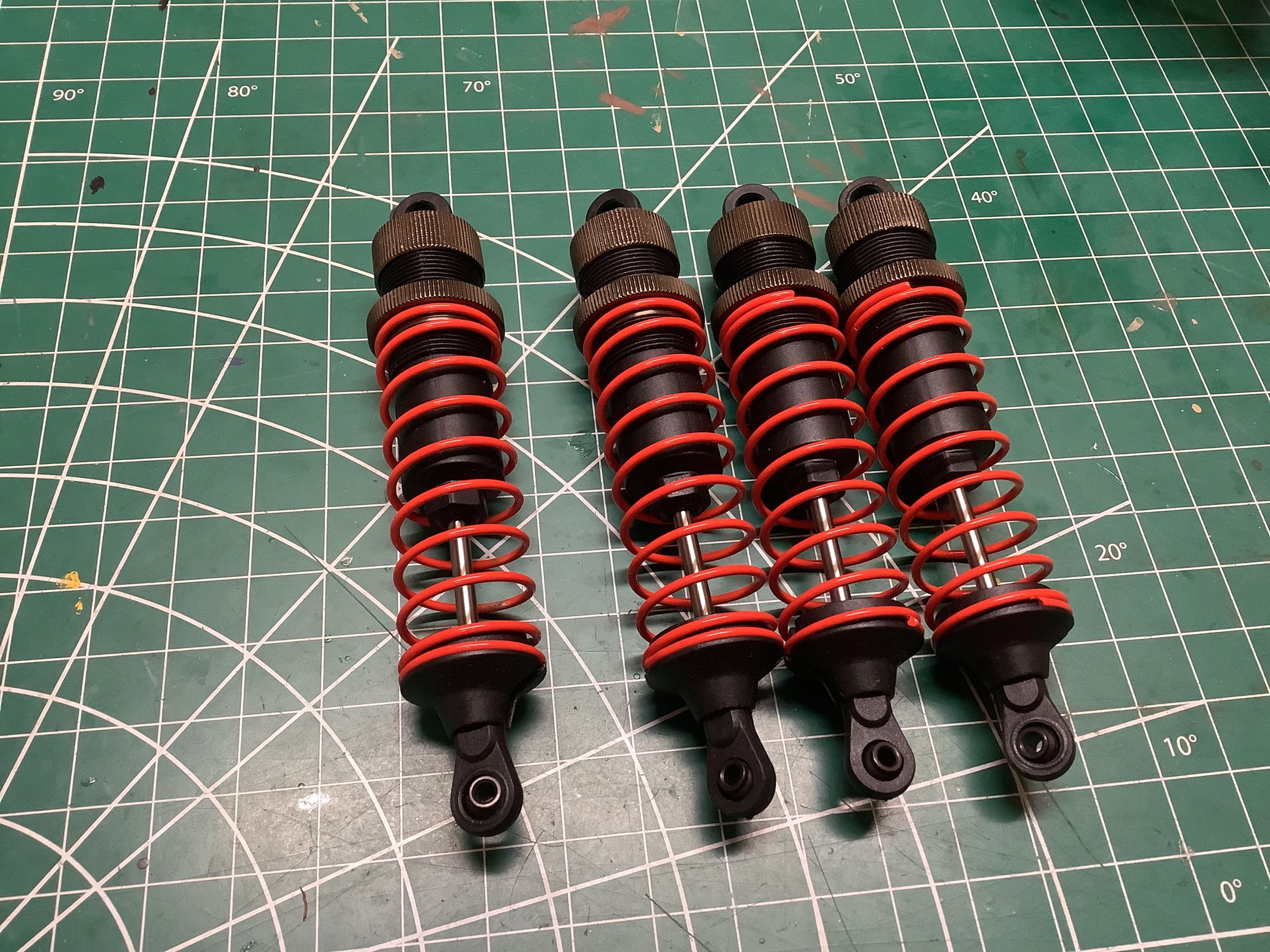
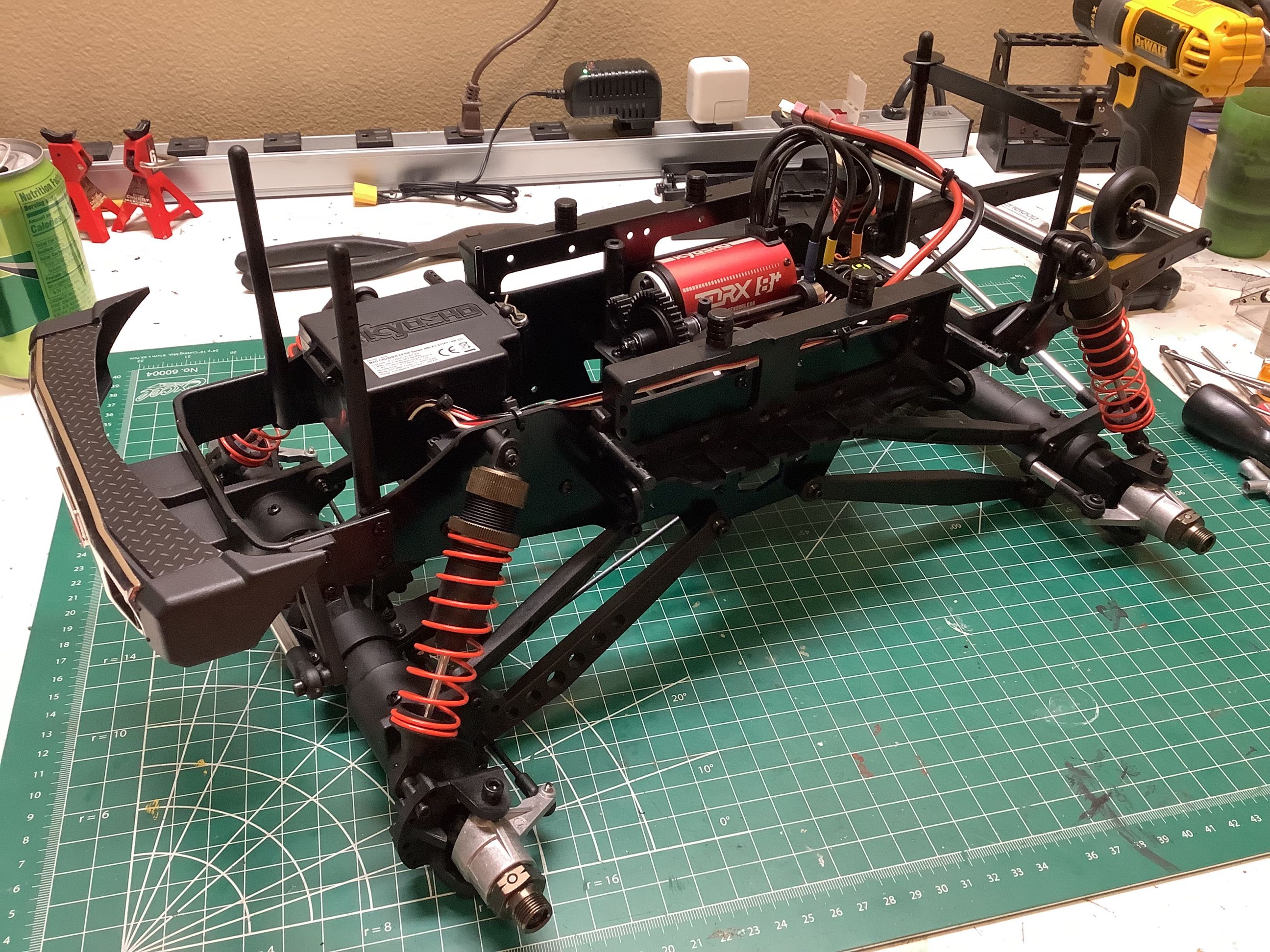
The large bore oil shocks are very nice, but the angle at which they are installed is very strange. They are tipped back a lot and also considerably inboard. I suppose this is just because the axles are so wide, but it makes for an unusual stance. They seem to soak up the bumps though. It is very strange for a 4-link suspension to also have a panhard bar, but the links are not triangulated so the lateral link is required.
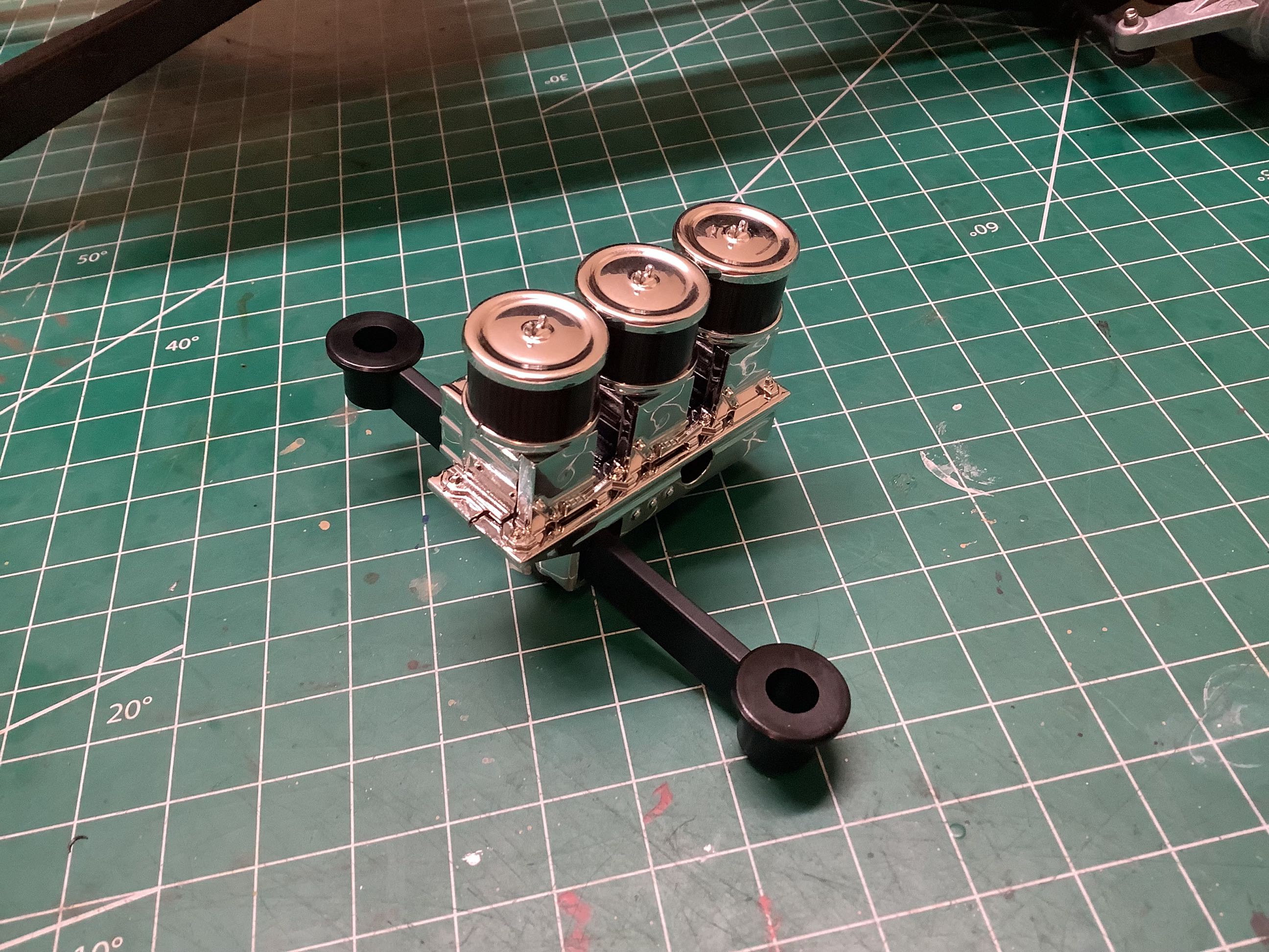
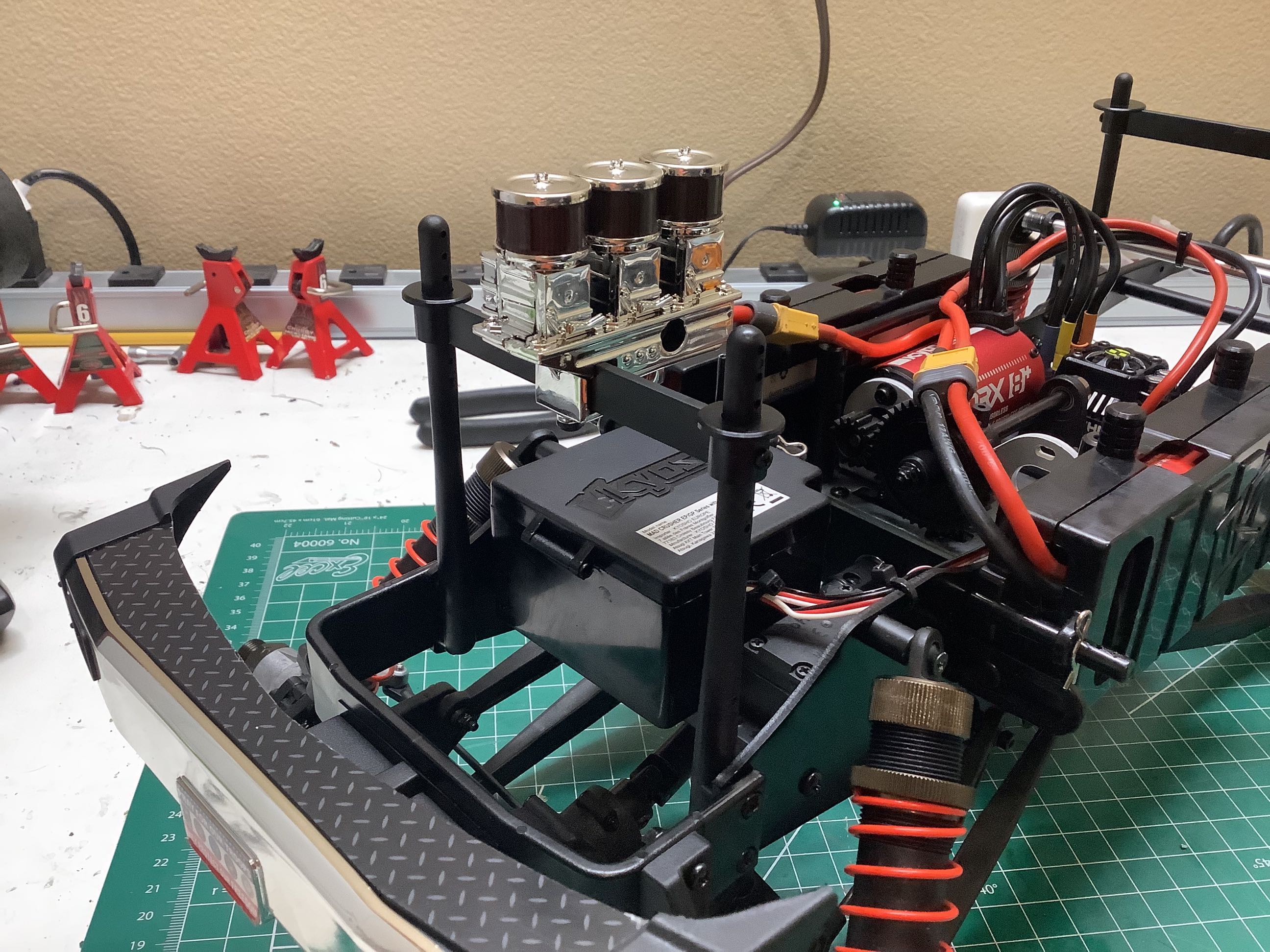
The triple carburetors and supercharger are not part of the body, they actually attach to the body posts and poke through a hole in the body. Why? It seems like I have asked that question quite a few times with this model.
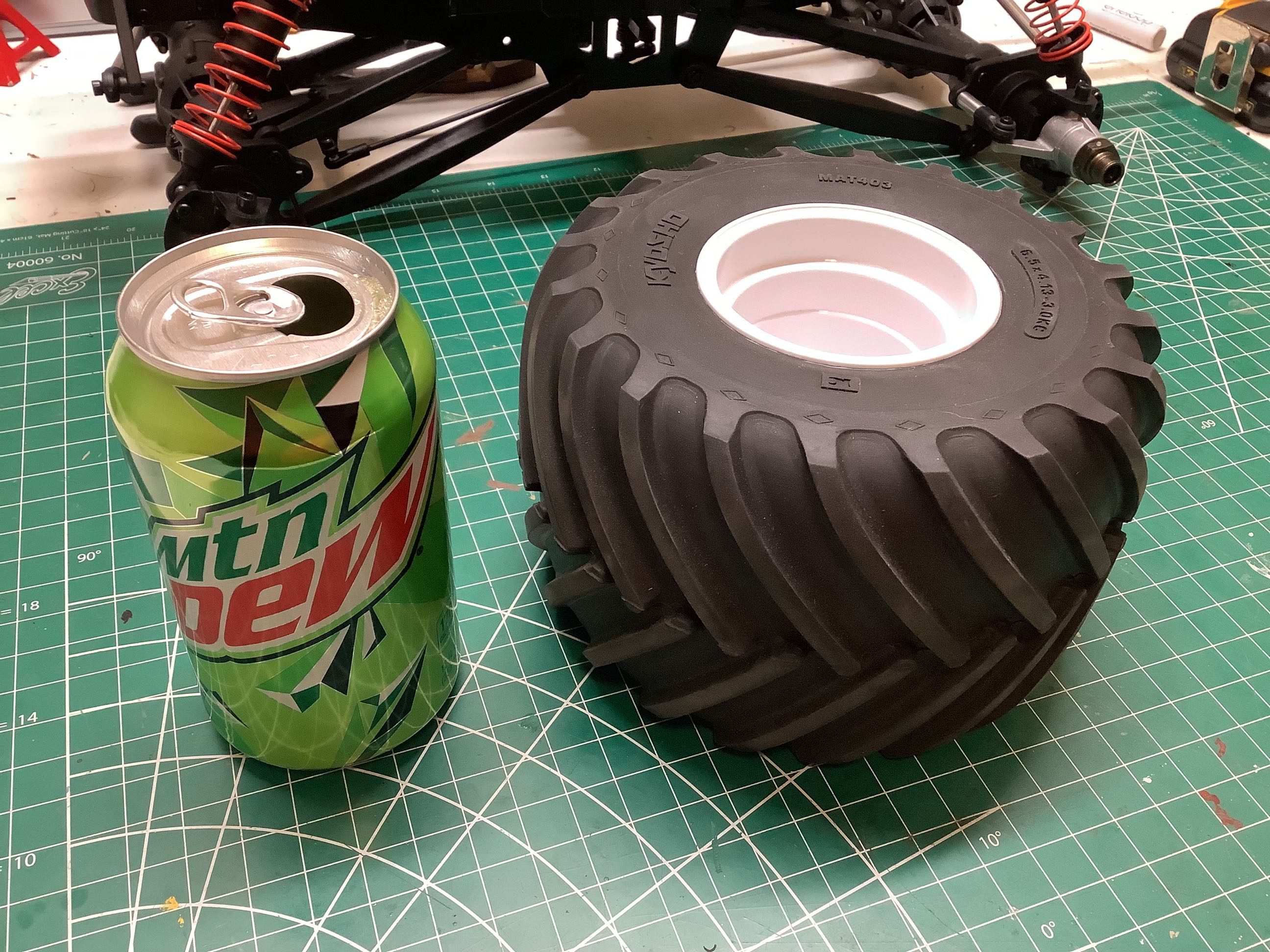
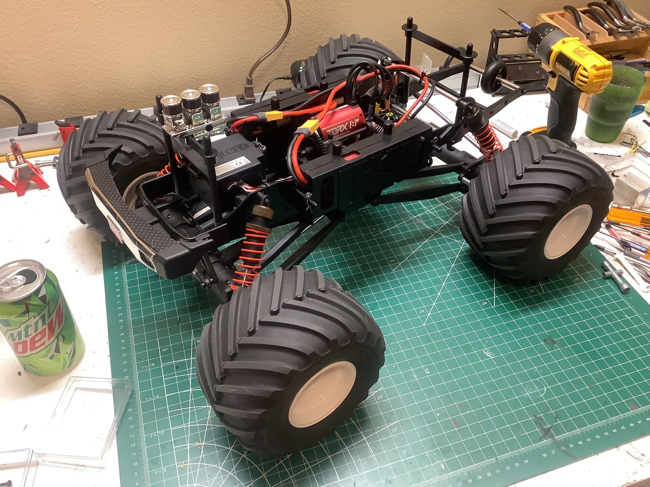
The tires are truly enormous as you would expect from a scale monster truck. They are roughly equivalent in size to what you would find on the Clodbuster. The installation of the wheels and tires completes the chassis.
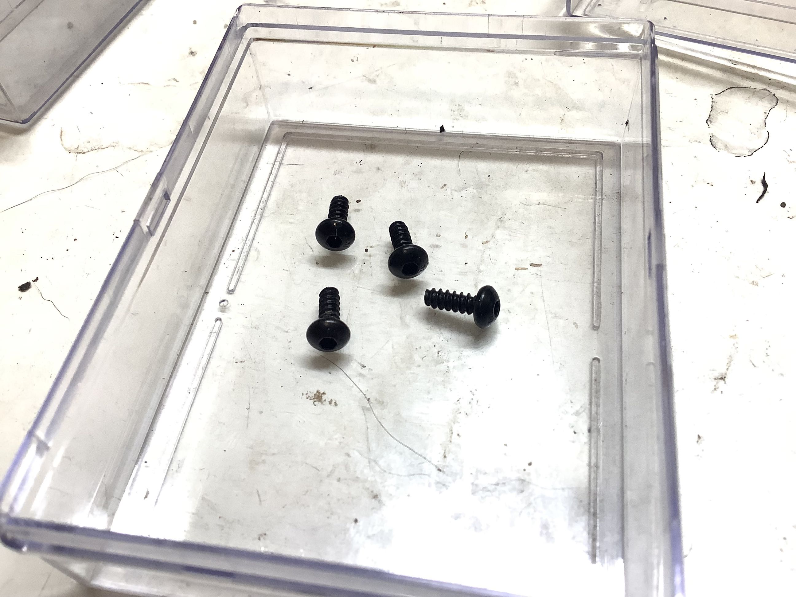
After completing the build I had these 4 screws left. That seems bad. It doesn't mean anything is missing though. As I built I made sure I installed all the right sizes per the instructions and that forced me to use a few fasteners from my own stock since some were missing. That implies that these screws were installed in the RTR but do not match the manual.