Tamiya TXT-1 Project
Page 1: Assembly
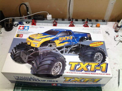
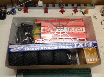
The TXT-1 comes in a massive box, most of which is occupied by the
tires, side frames, and two copies of the body. The box is
amazingly heavy and each time I withdrew another set of parts I became
more excited about the build. I bought this set in an open box so I
had to go through the whole inventory in detail and a handful of things
were missing. There were some E-clips missing from a hardware
bag, the wheel hexes were missing, and the drive shafts were from some
other model and didn't fit.
This is as big a pile of parts I have ever seen for a Tamiya kit, and
perhaps any kit. There are 8 labelled hardware bags, but they
don't correspond to the build order. All the bags have to be
opened right away because each step draws hardware from multiple
bags. There are loads more bits of hardware that aren't in any of
the 8 smaller bags and these included links, nylon gears, metal
differential gears, bearings, drive shafts, and a myriad of other
parts. Then there are a dozen or so plastic parts trees and it
would be impossible to miss those tremendous wheels and tires.
The central gearbox is taken from the Juggernaut 2 although you
can see "2001" molded into the housing which suggests it has been
updated. If there is a difference, I can't find it. Even the
instructions are identical. The shaft you see on
the top in the first picture is the output shaft which goes both
forward and aft. It is on the bottom in the second picture.
There are two stages of gear reduction inside the gearbox at this point,
and there will be a total of four once the motors are attached.
You can see the very large pitch of the strong gears.
Addendum: I figured it out. The output shaft
changed diameter from 5mm to 6mm between the Juggernaut and the
TXT-1. This actually doesn't change the housing any because the
bearing support is still 11mm. The bearings went from 11x5 to
11x6.
The dual motor system is also taken directly from the
Juggernaut. The twin motors operate in parallel on a single spur
gear. The gear pitch at this point in the drive train is smaller,
but the gears get larger as the torque increases further
downstream. There are a couple of metal heat sinks attached to the
outside of the gearbox.
The chassis is brand new. We'll start with the front and rear
bumpers which act as intercostals between the frame rails. These
are no mere C-channels, the frame rails are fully machined
fittings. I was going to use the word "truss", but the areas are
not triangular nor are the members pinned. The rocker arms for the
cantilevered suspension pivot on the frame rails.
Here is the completed frame with the central gearbox installed.
The gearbox serves as the primary cross member for the frame
rails. The other cross members use aluminum tubes as
spacers. The whole thing is very rigid at this point.
The axle housings are taken directly from the Juggernaut as well.
Note the extra stage of bevel gear reduction inside the top of the
housing. While most differential gears use a bevel ring gear, this
one uses a spur. The massive straight cut teeth (the largest in
the model) mate with another gear above for one last stage of gear
reduction. That's six stages in total. All of the gears
within the axle are metal.
Now the differentials fit inside the axle housings and mate to the
integrated gearboxes. The gearbox covers are different than the
Juggernaut because while that model has a chassis mounted servo and a
servo saver inside the cover, the TXT-1 uses axle mounted servos which
makes for much more direct and effective steering of those huge
tires. Note the "2000" molded into the axles versus the "2001" on
the cover.
The steering hubs date all the way to the Clod Buster and still have
that name molded into them. The suspension links, however, are
brand new. The Clod used complex molded plastic links, the Jugg
used simple plastic I-beams, and now we have tubular aluminum
links. Eight links are used for the triangulated suspension and
the four smaller links are pushrods for the shocks. There are also
steering links front and back. That's a lot of links to build.
Now the axles can be attached to the frame using all those links
resulting in a nearly completed chassis. The completed
cantilevered suspension is seen clearly on the left. The oil
filled shocks are located along the frame rails and driven by rocker
arms. From below you can see how the pumpkins face down instead of
out. The drive shafts are strong telescoping steel units.
They look like they come from the Juggernaut but they don't.
The inside diameter of the U-joint changed from 5mm to 6mm to match the
larger transmission output shaft. I found this out the hard way
because my kit had the wrong drive shafts which didn't fit.
The steering system is new for this model. The servo is mounted in
the skid plate ahead of the axle and drives the right hand steering
knuckle directly. The rear knuckles are locked per instructions,
but can be built exactly like the front for four wheel steering.
That's how I built it.
This plate contains the original mechanical speed controller
system. This includes the MSC itself, a servo, a battery box, and a
resistor. I'm not using any of this for my model but I wanted to
include it anyway for historical accuracy. I used an old broken
servo. For the real power system I used a dual motor ESC from
Hobbywing as shown, and I'm also running off a 2s Li-Po battery making
the whole thing pretty modern. The ESC is also capable of powering
these motors on 3s which I occasionally take advantage of. It
will probably burn out the motors in the long term, but they are cheap
and the extra speed is fun.
The last bits of the chassis are the supports for the body posts and
then installation of the wheels and tires. These are the tires
from the original Clod Buster which differ from the rounded versions
used only on the Juggernaut.
I'm quite glad that the body came pre-painted since I'm not sure how I
would have managed the effects. There were still stickers to apply
though. The picture on the right shows the lovely result.
I had previously built the 1/18 scale TLT-1 which is clearly intended to
be a smaller copy of the TXT-1. That's not hard to see in this
comparison photo.
©2019 Eric Albrecht

