Tamiya TRF 418 Project
Page 2: Assembling the Chassis
While writing about this build, I am going to concentrate on the
differences between this and the last chassis in the TRF line I built
(the TRF 417X)
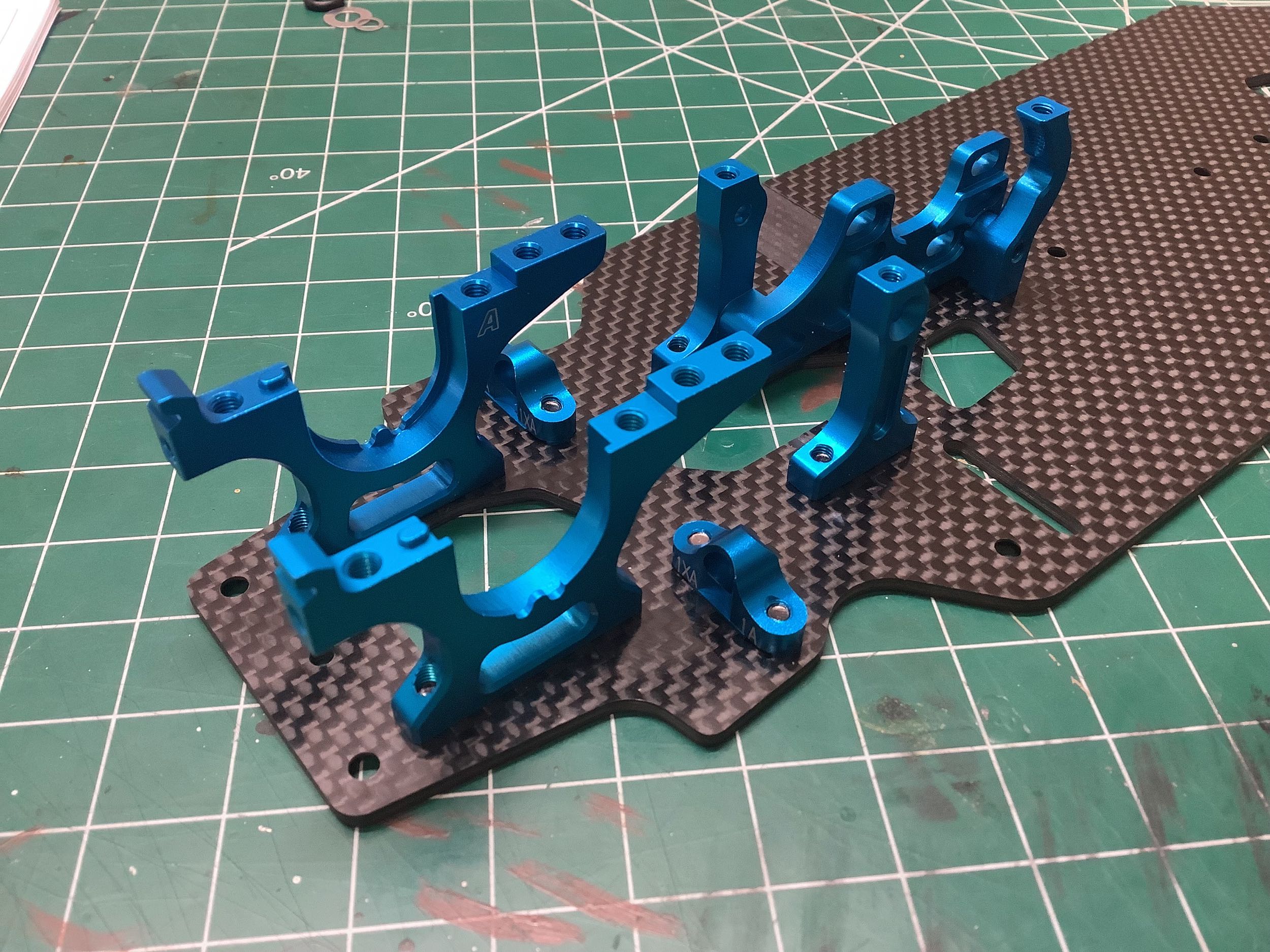
While the TRF 417 series began the build with the differentials, the TRF
418 goes straight to the rear bulkheads and motor mount. The
bulkheads are identical for front and rear and are very similar in
design to those of the TRF 417, but are not the same parts. One
important addition is the locating pins on the bottom which help
position them on the chassis plate while the screws are installed.
The forward suspension mounts have changed significantly (more on this
below). The 3-piece motor mount is new with separate left and
right bulkheads and a center post for lateral support.
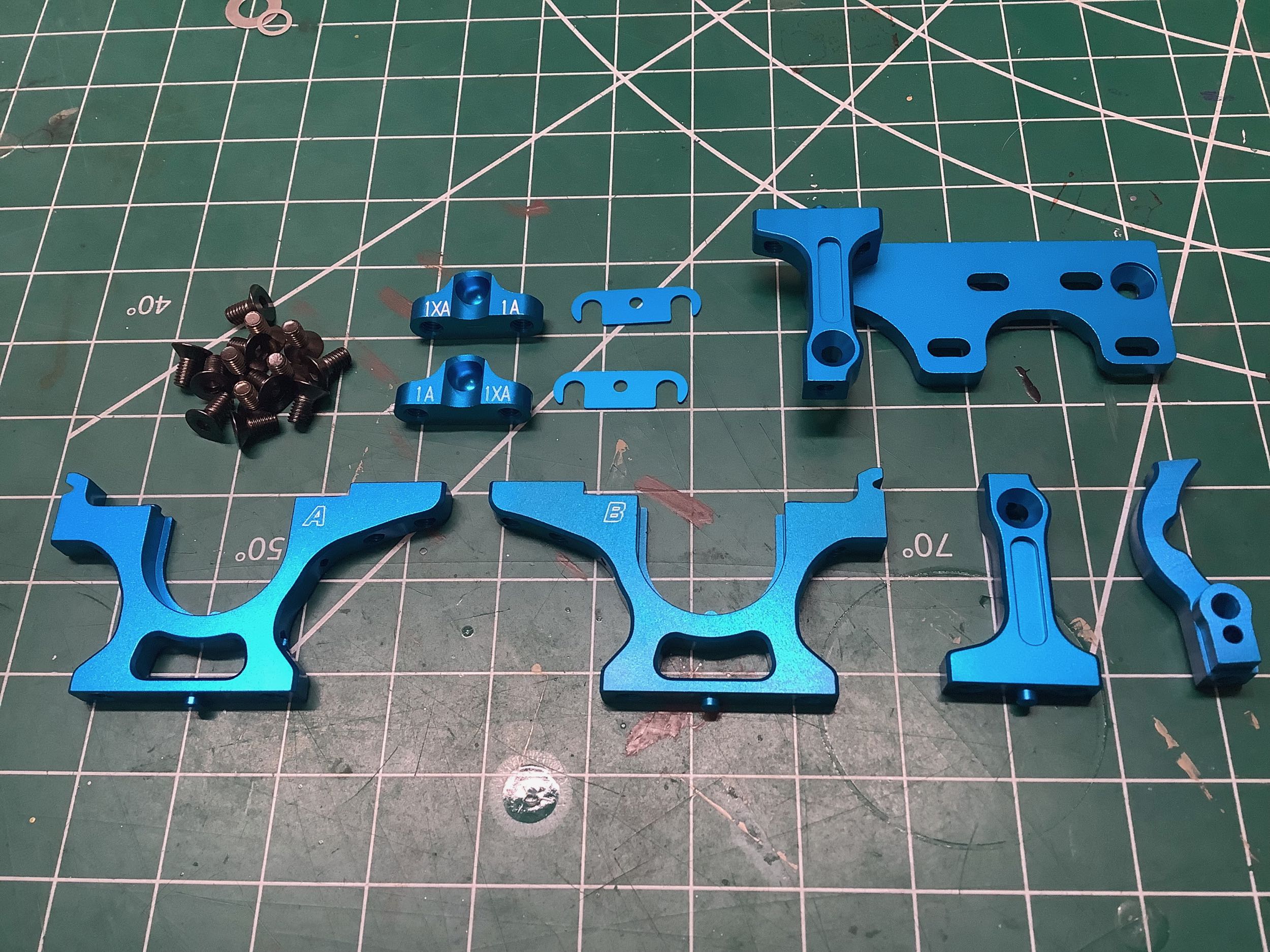
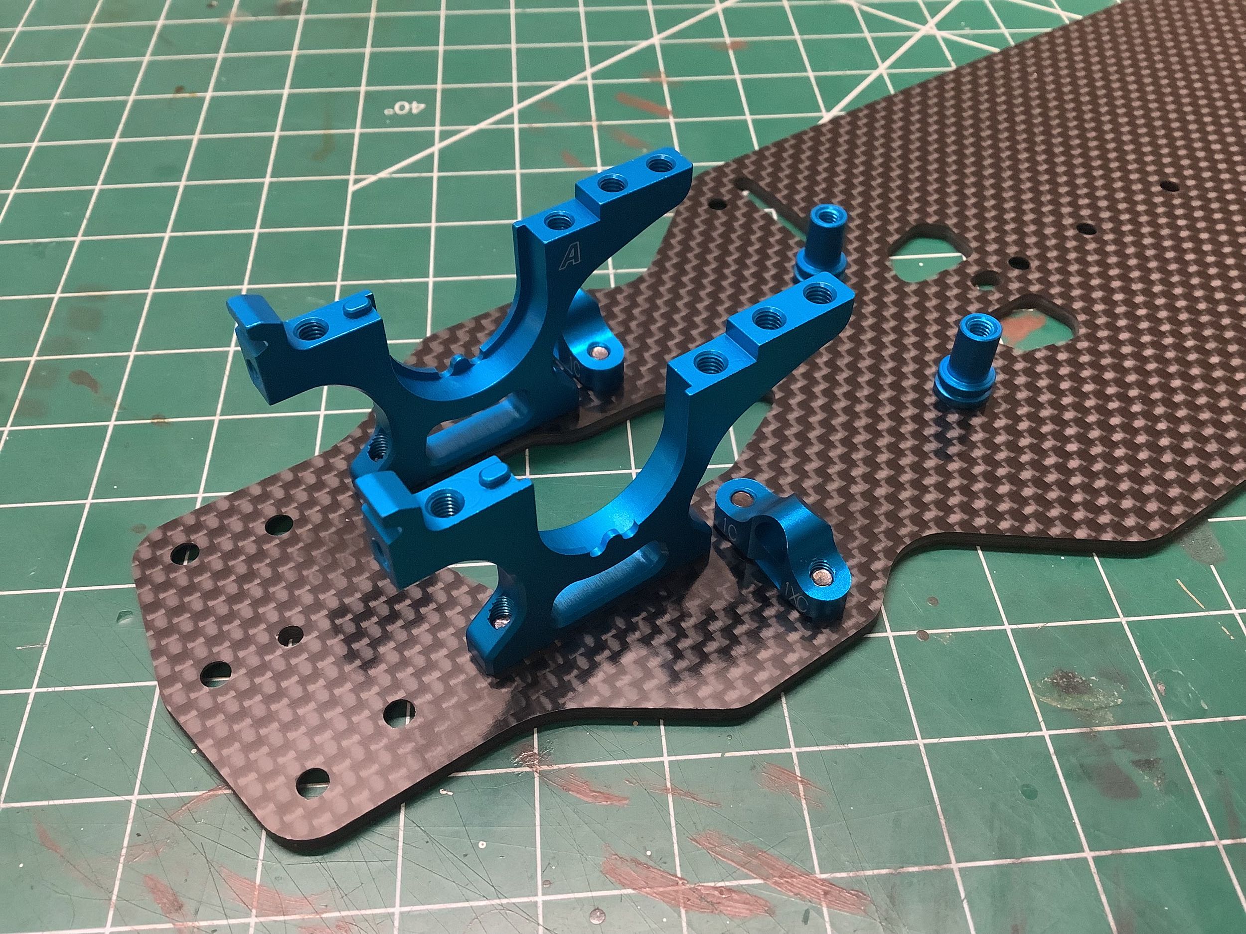
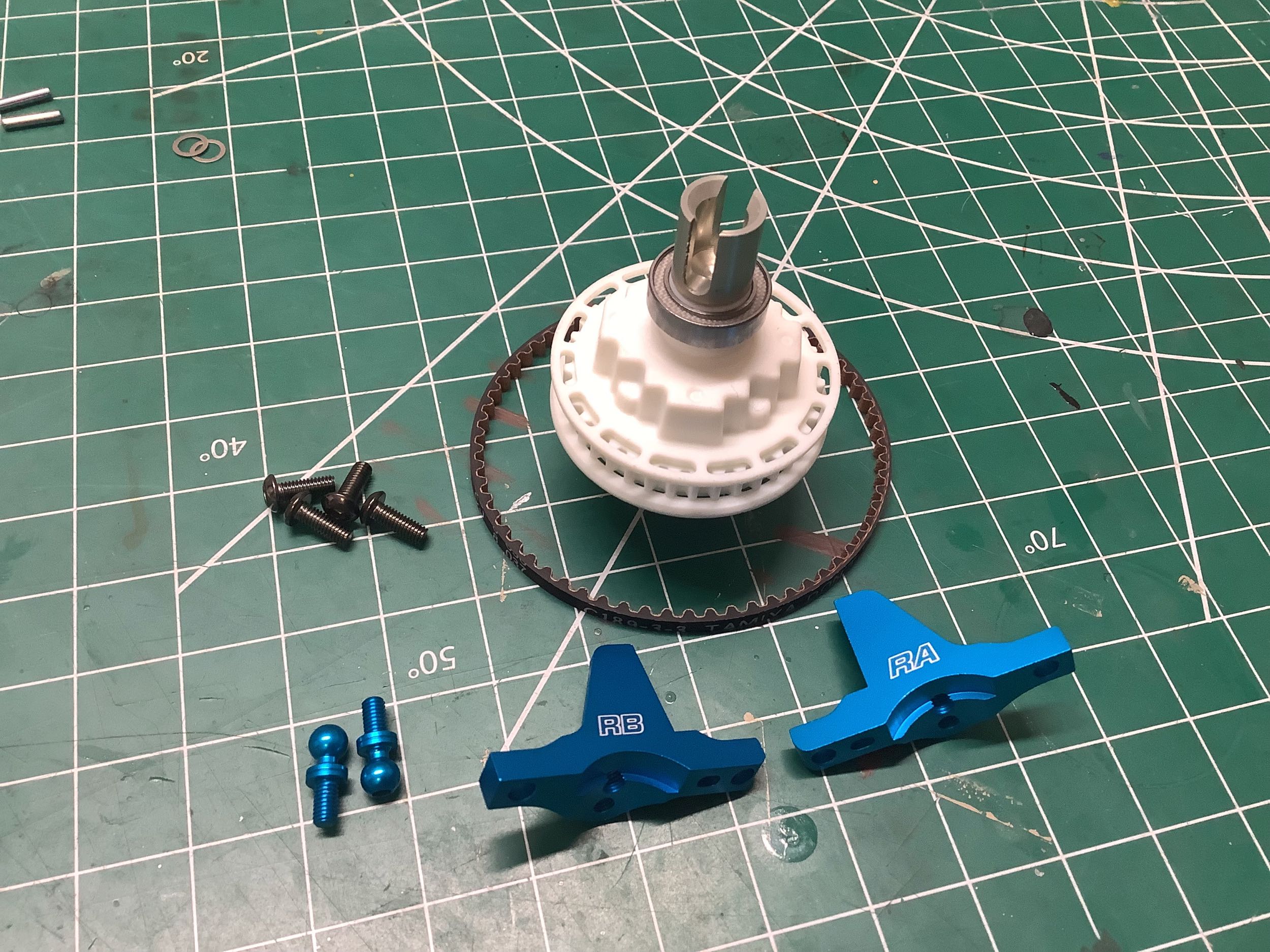
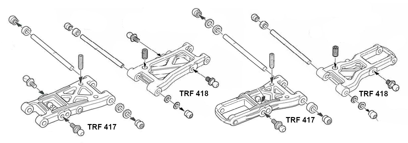
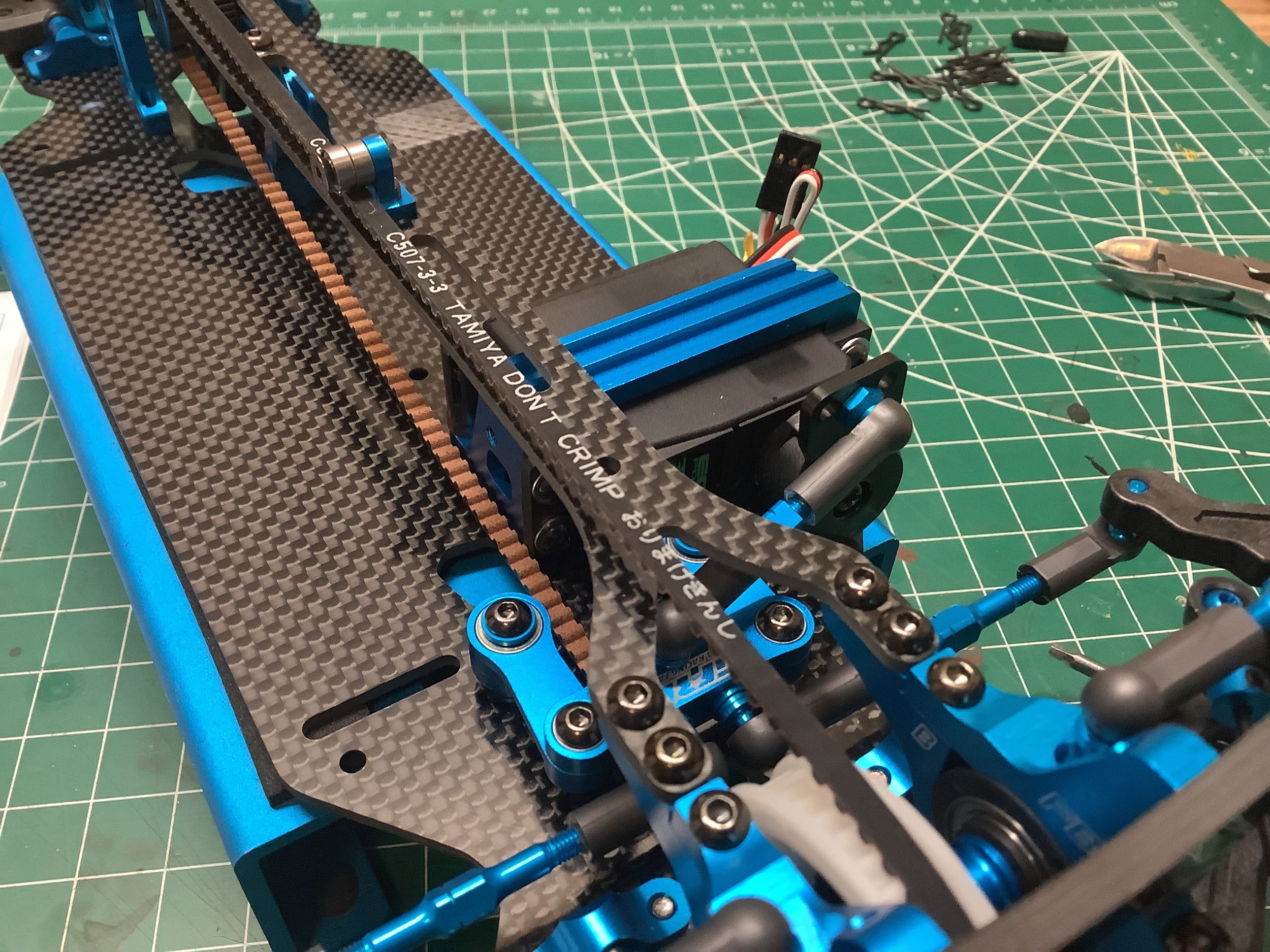
The forward suspension mounts have changed from a one piece aluminum bar
to two separate aluminum parts. These were previously introduced
on the front suspension of the TRF 417 V5. The previous generation
solid blocks were labelled 1XD - 1F (11 varieties) and could be used to
alter the toe from -5° to 5° depending on how they were combined.
The split mounts were compatible and used the same nomenclature but
were only available from 1XD - 1D (9 varieties). Starting with the
TRF 418 the chassis tended to use the split blocks for the suspension
mounts nearer the center of the chassis to clear the belts, while the
mounts at the ends continued to use the solid design. Note in the
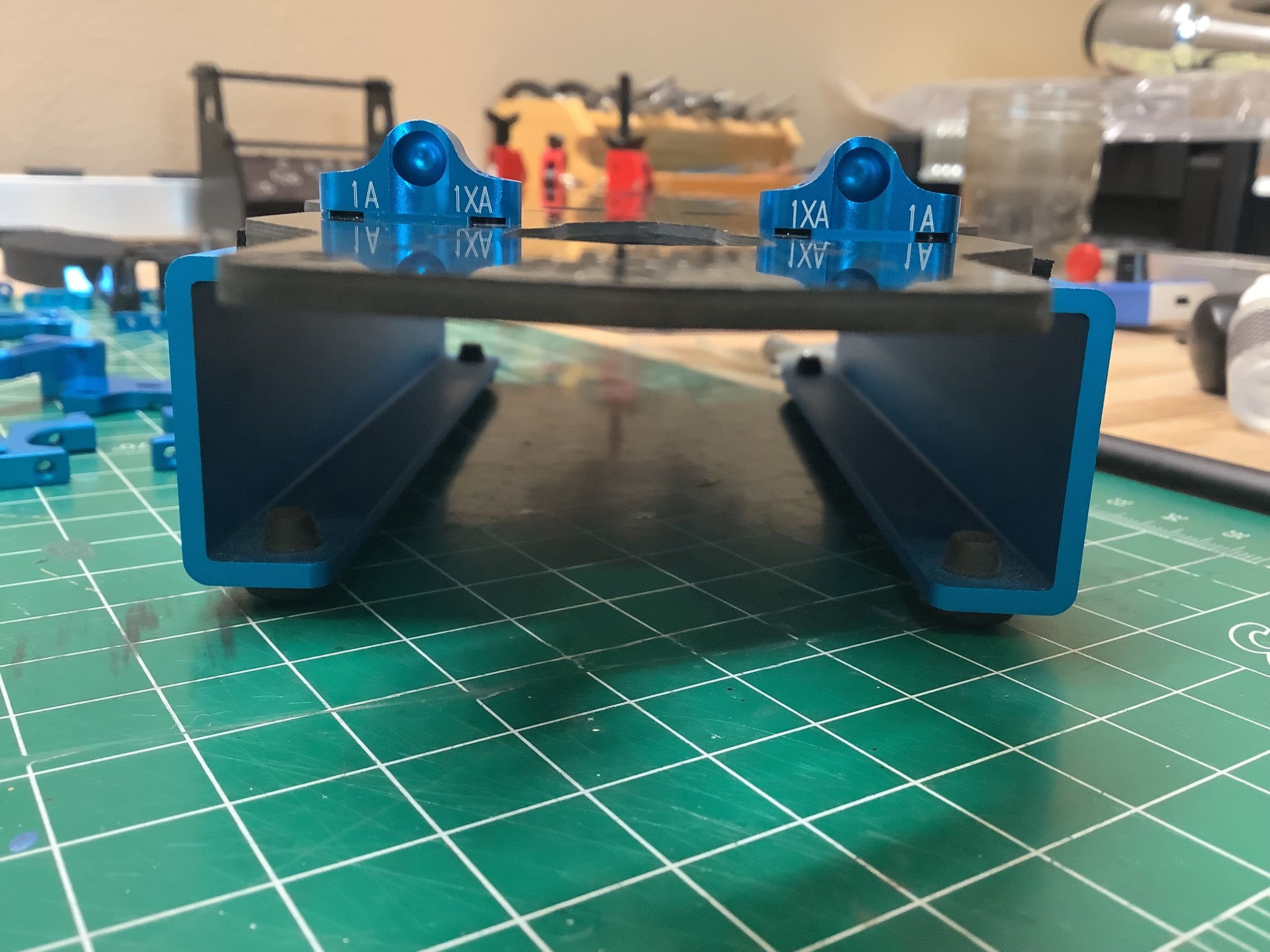
picture above that the split mounts are labelled both 1A and 1XA.
Since the pockets are slightly off center, the same parts can be used
for either width depending on whether they are installed with the 1A
toward the center or the 1XA toward the center. These are
installed in the 1XA configuration which is actually the same width that
was used in the same position on the TRF 417X. There are also
0.5mm shims under the suspension blocks to increase the roll
center. Note that if the outer blocks did not also use the same
shims, it would result in a skid angle since the hinge pins would be
slanted down.
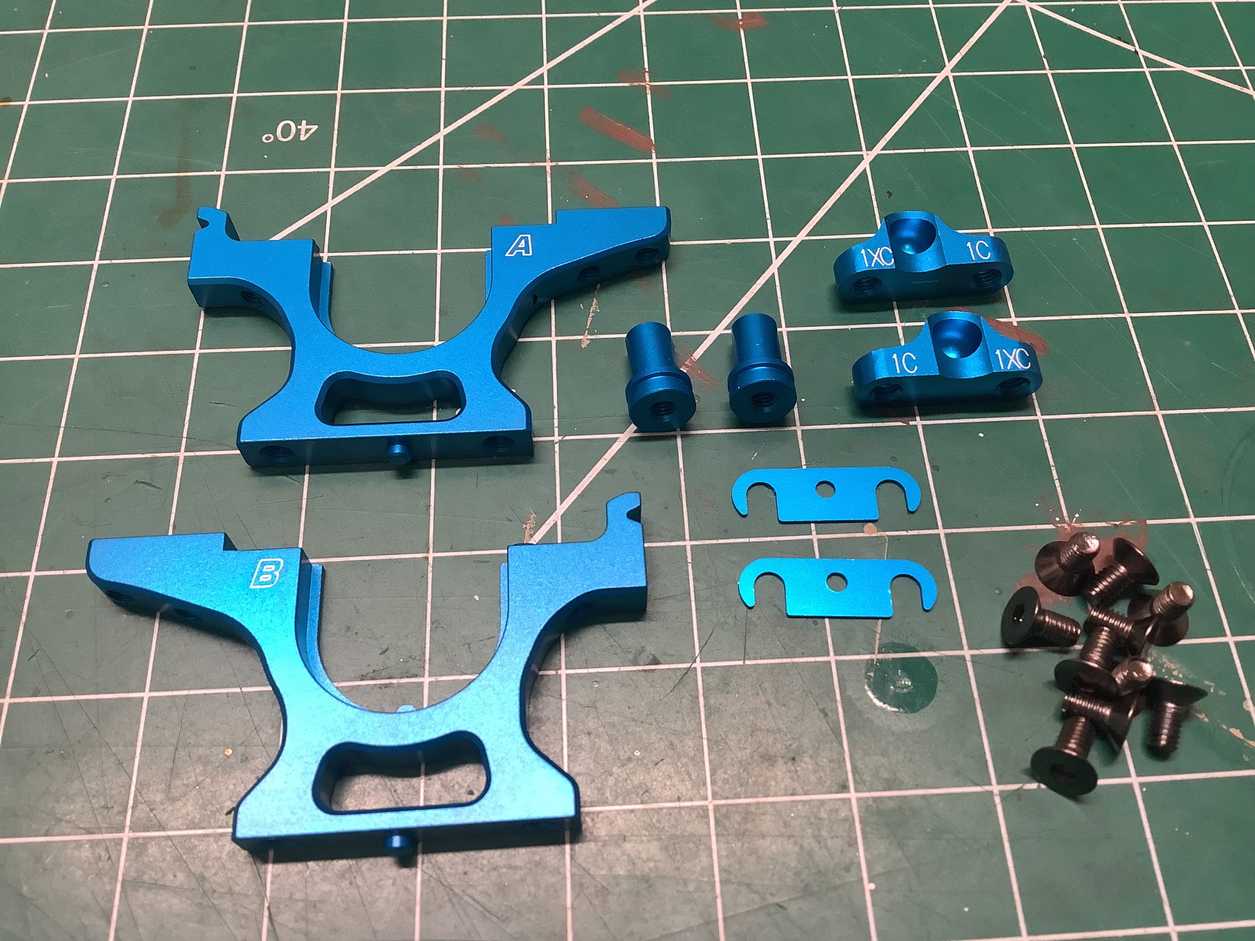
The front end uses the same bulkheads but wider 1C suspension blocks
(with the same 0.5mm shims). The aluminum steering posts are also
installed in this step.
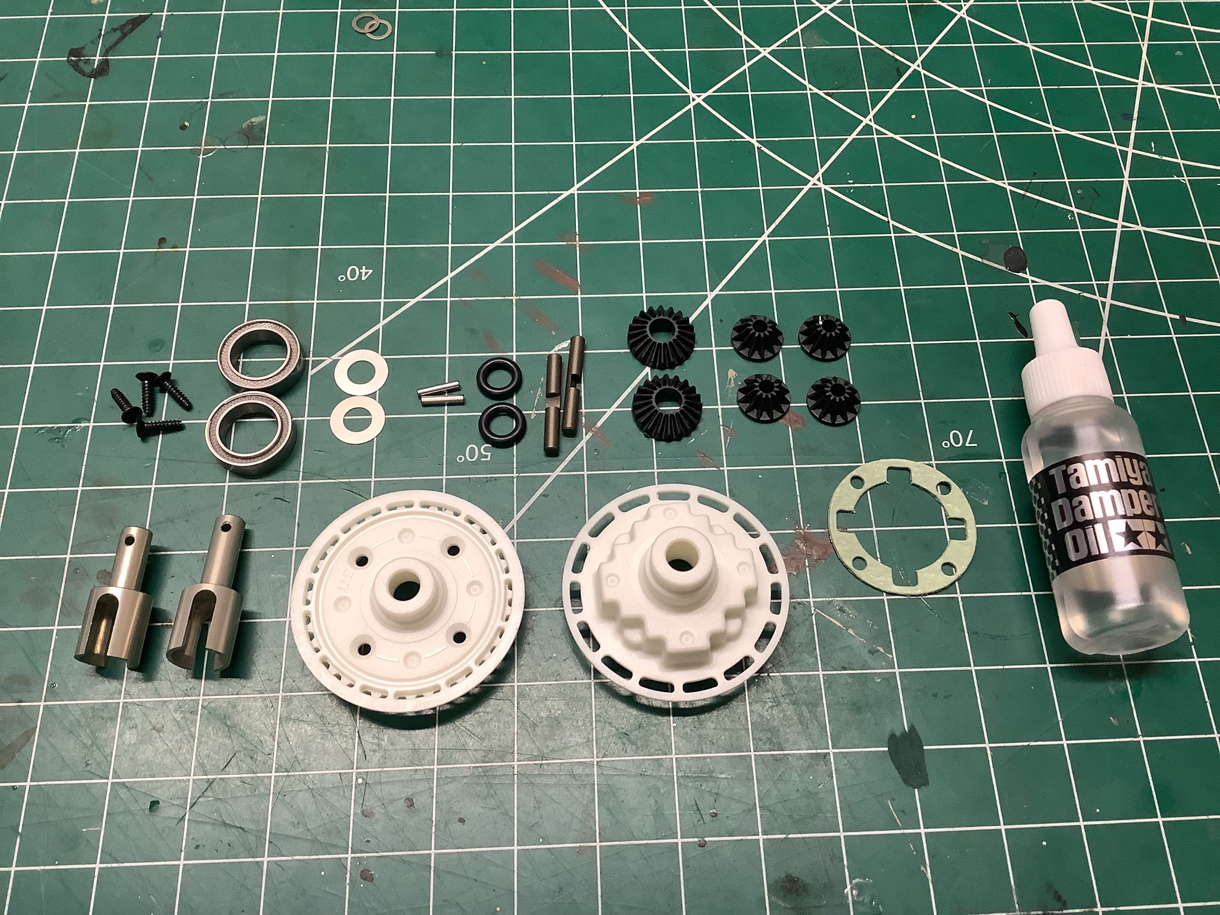
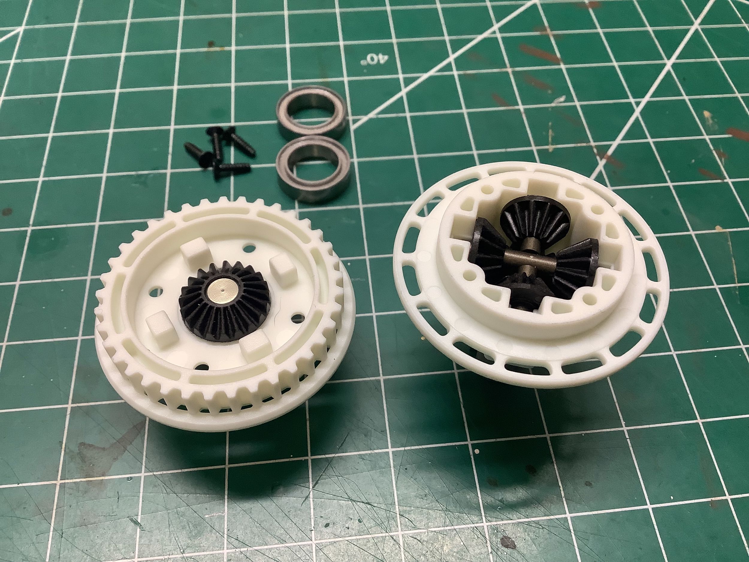
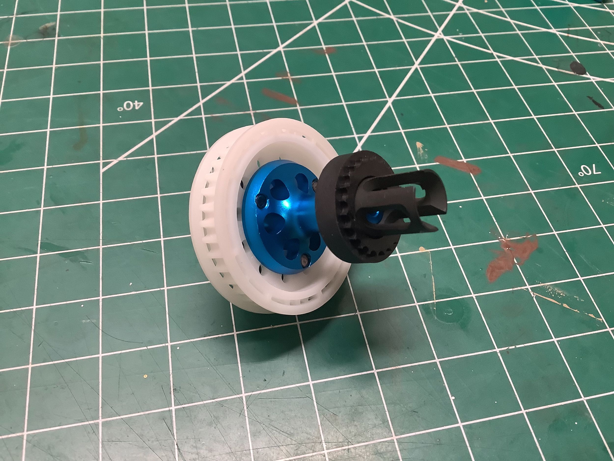
Time to build the rear gear differential. This oil filled unit has
an integrated 37T pulley and seems to use the same parts as the rear
differential on the TRF 417X.
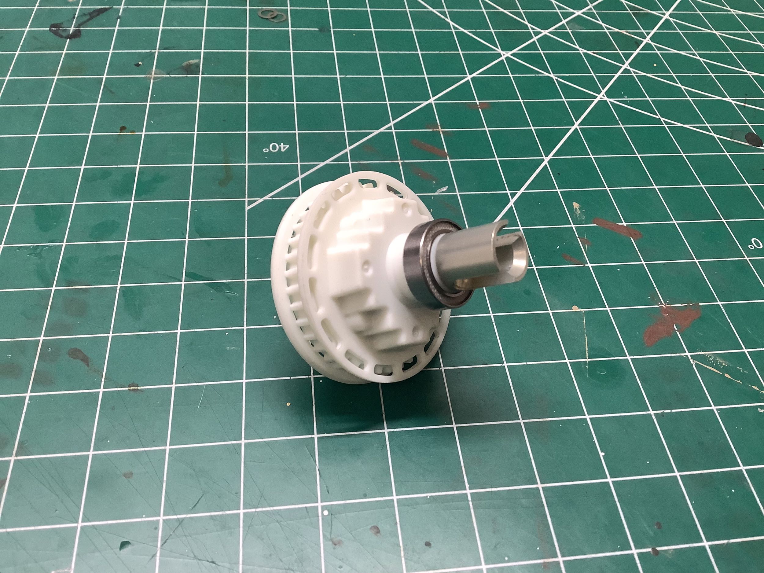
Here's the completed rear differential. The drive cups were
slightly strengthened on the TRF 417 V5 and carried forward here.
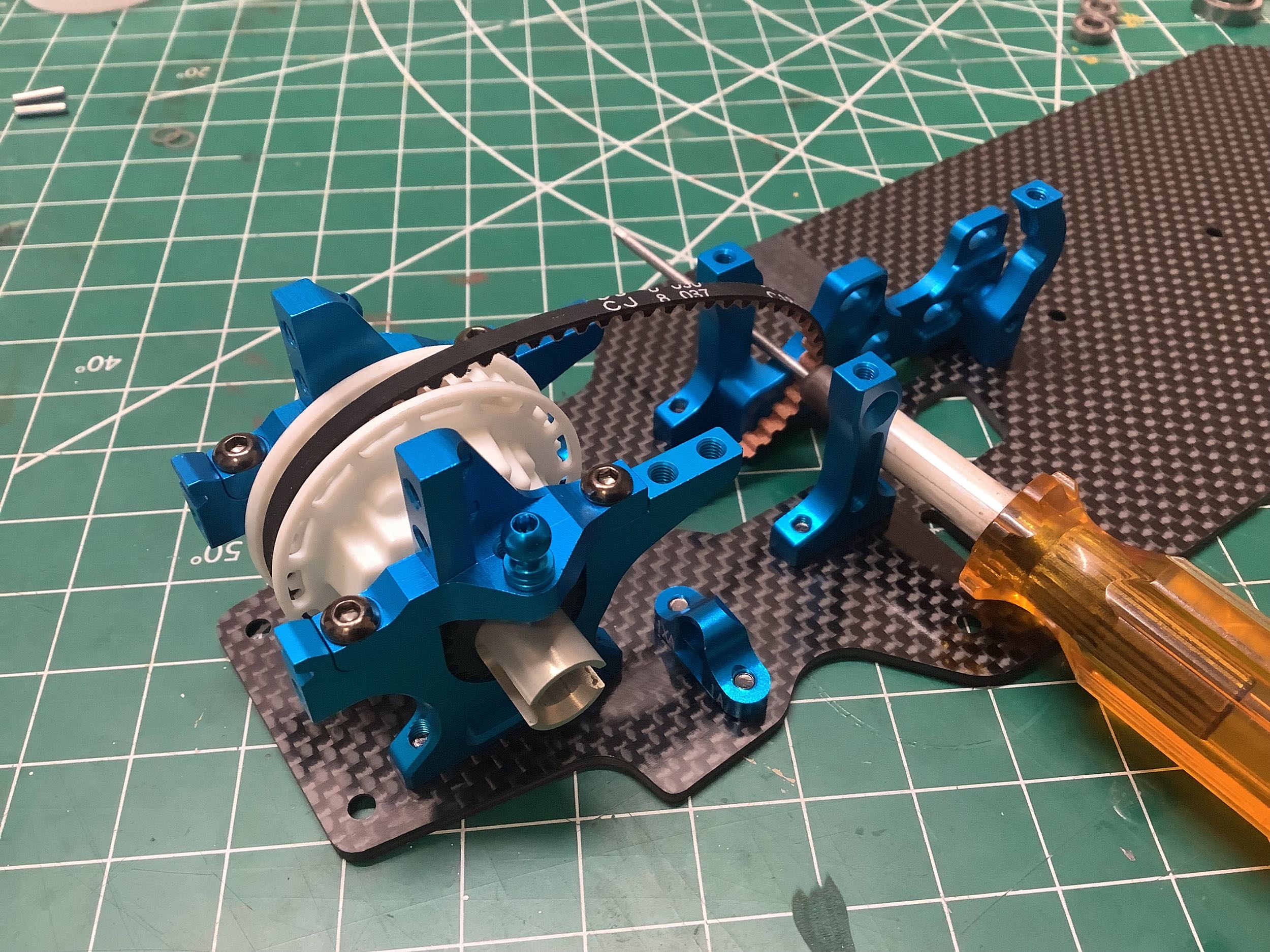
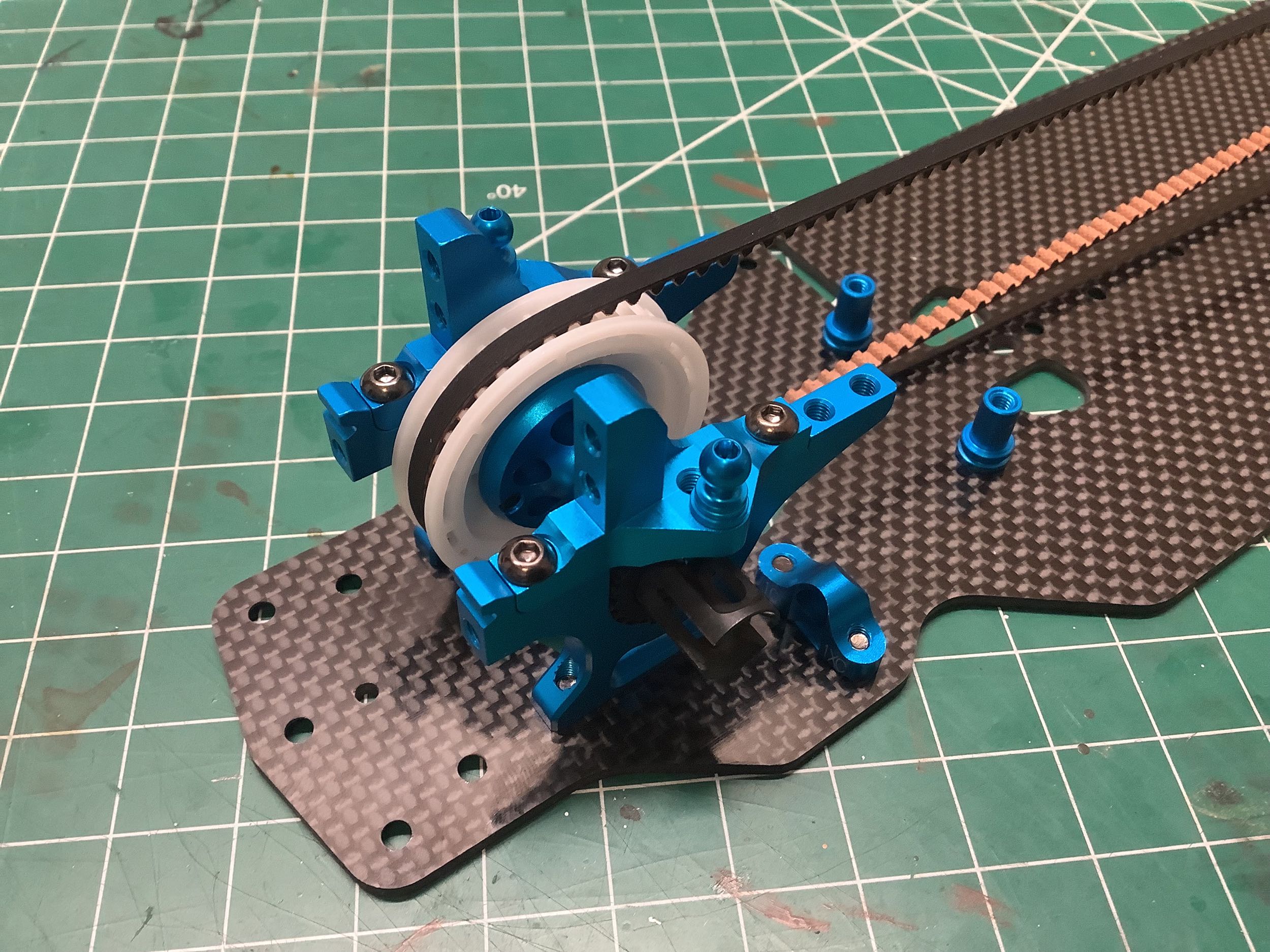
Now the rear differential can be installed in the bulkheads and captured
by the upper bulkhead caps. These are extremely similar to the
parts from the TRF 417 but they have only two hole options for the
camber links instead of 3. The belt tension is still controlled
with the same eccentric bearing blocks.
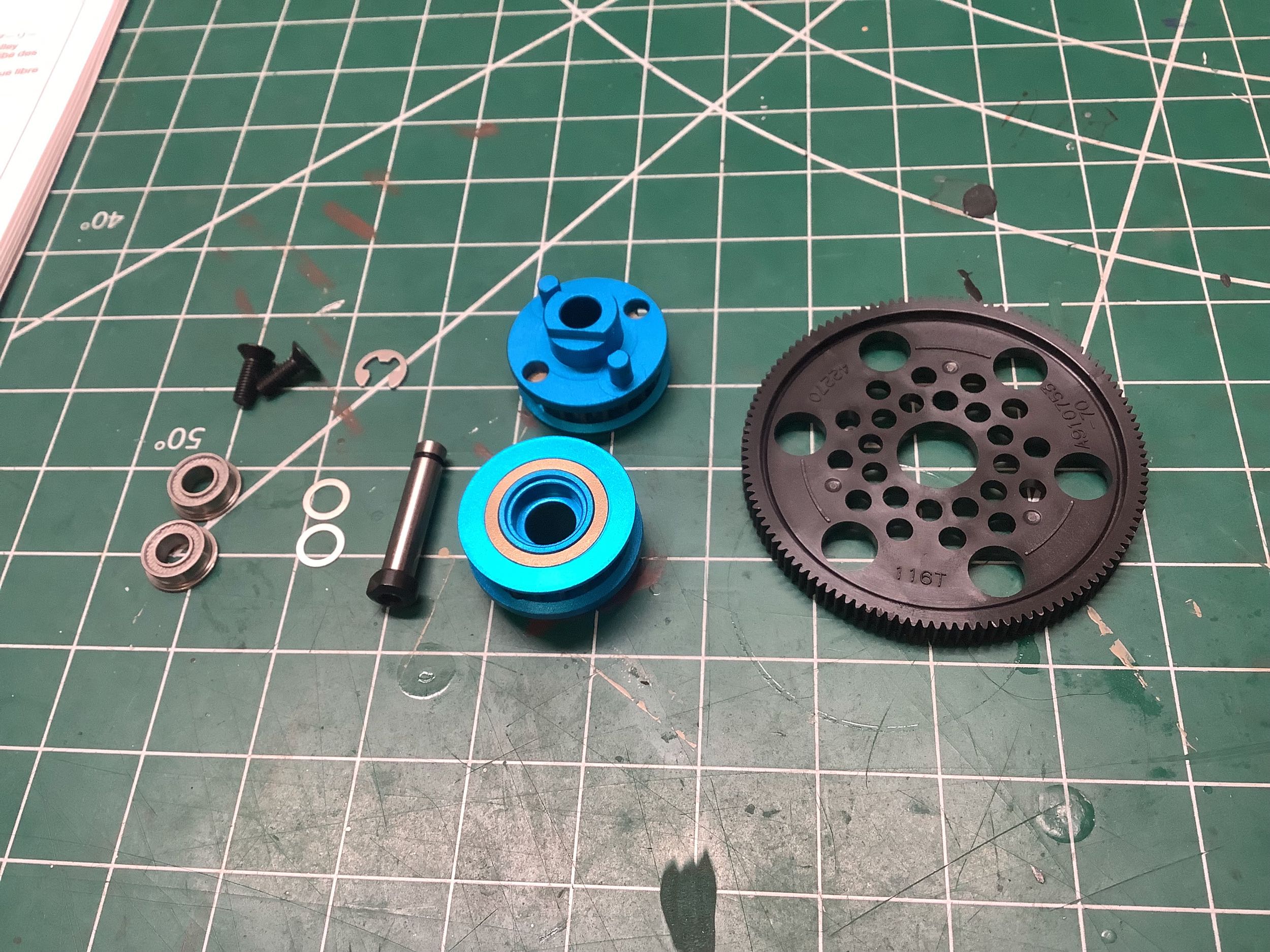
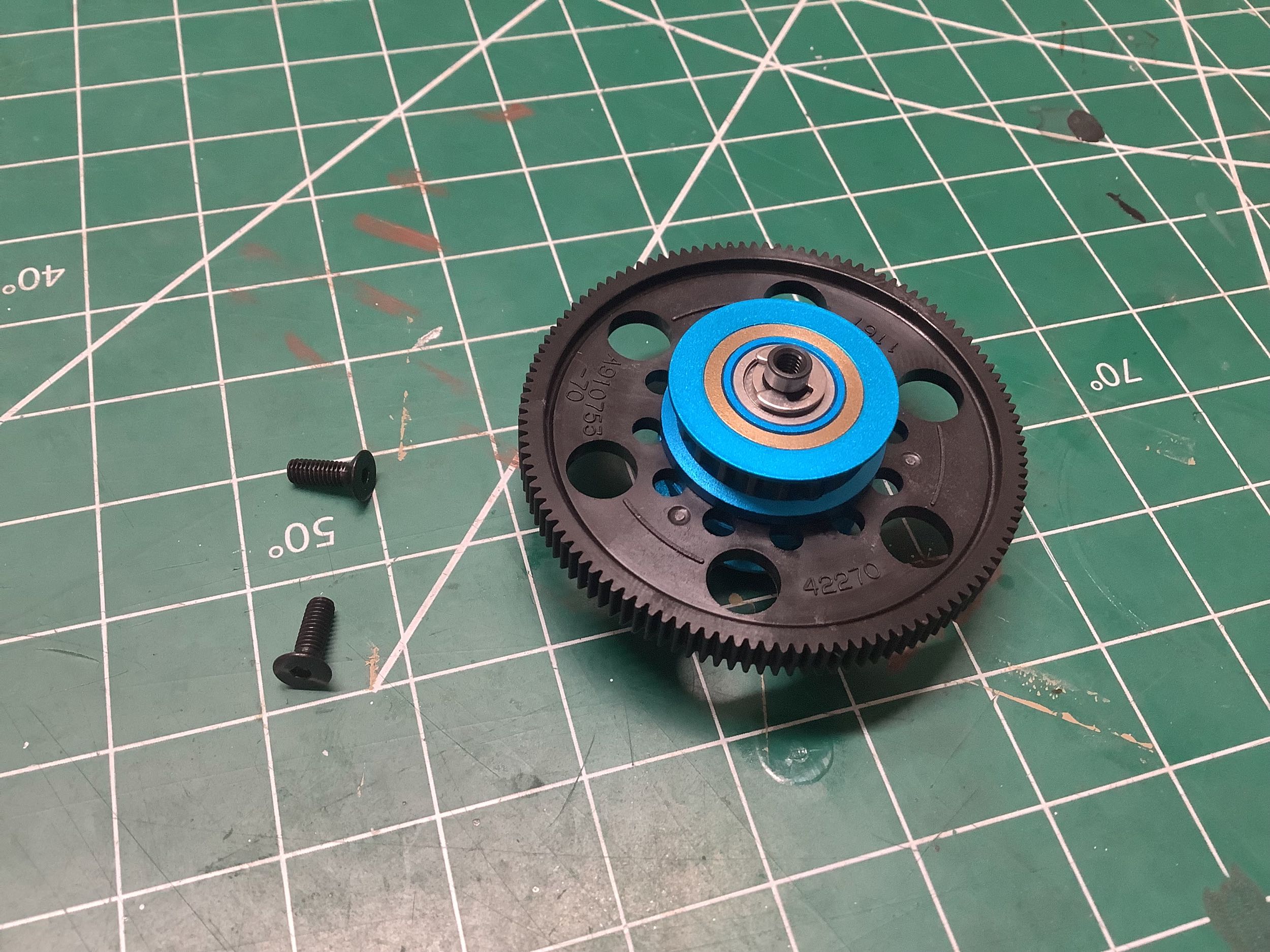
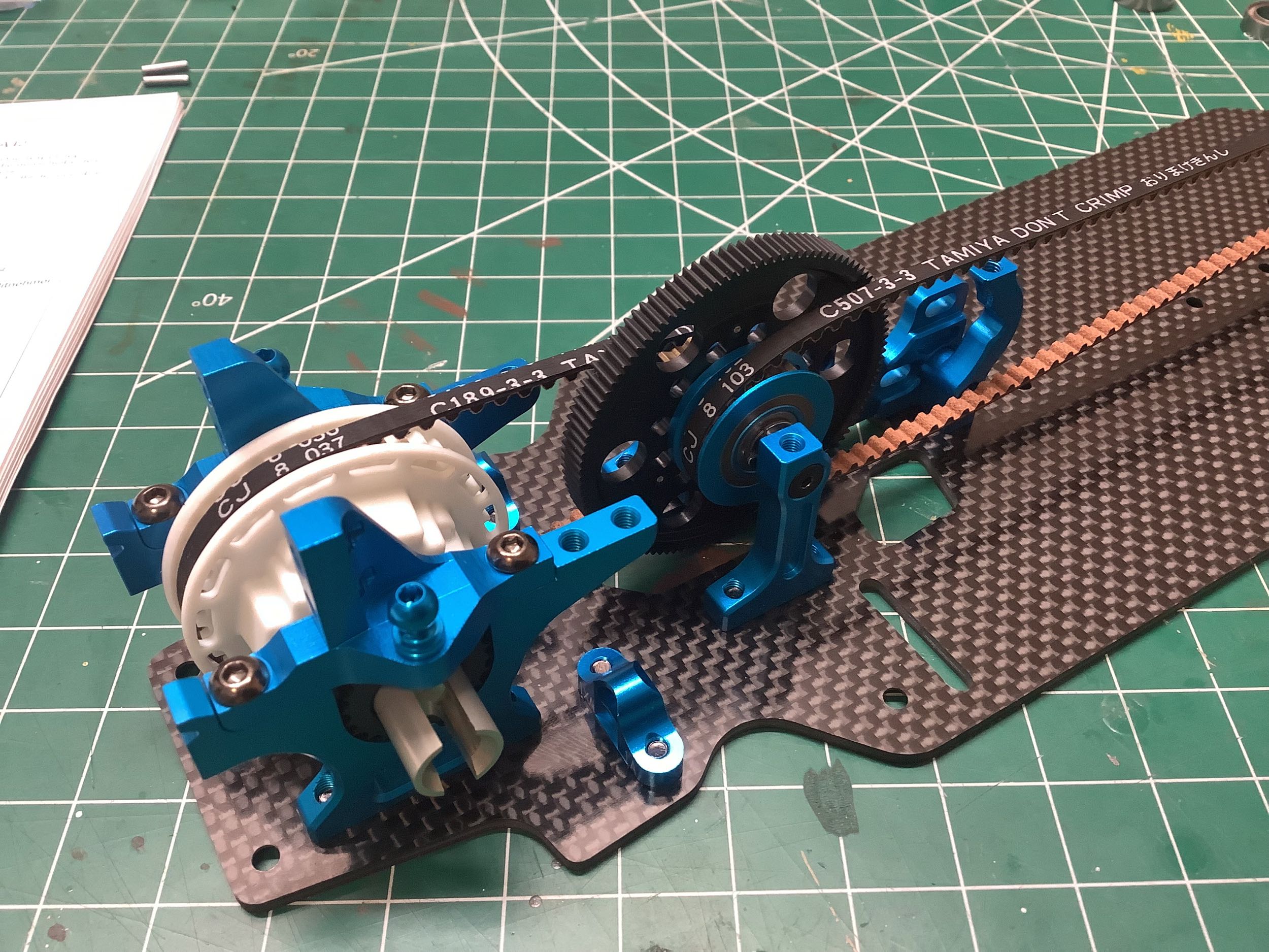
The center shaft is next and incorporates the spur gear and center
pulleys. The spur gear now has 116T instead of the previous
options of 111T and 113T. The spur gear actually has the kit
number molded into it indicating that it was new for this model.
The center pulleys have increased from
19T to 20T. The pulleys lock together with a combination of pins
and flats. The pins also lock them to the spur gear. There
is no center one-way bearing.
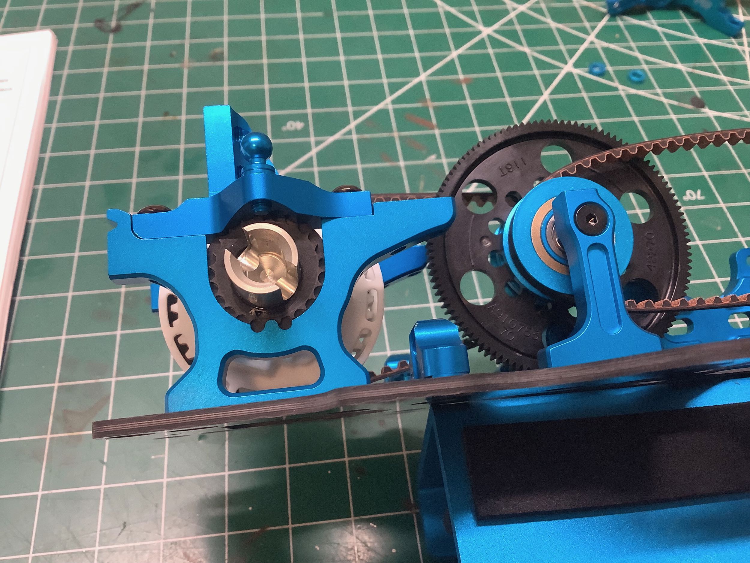
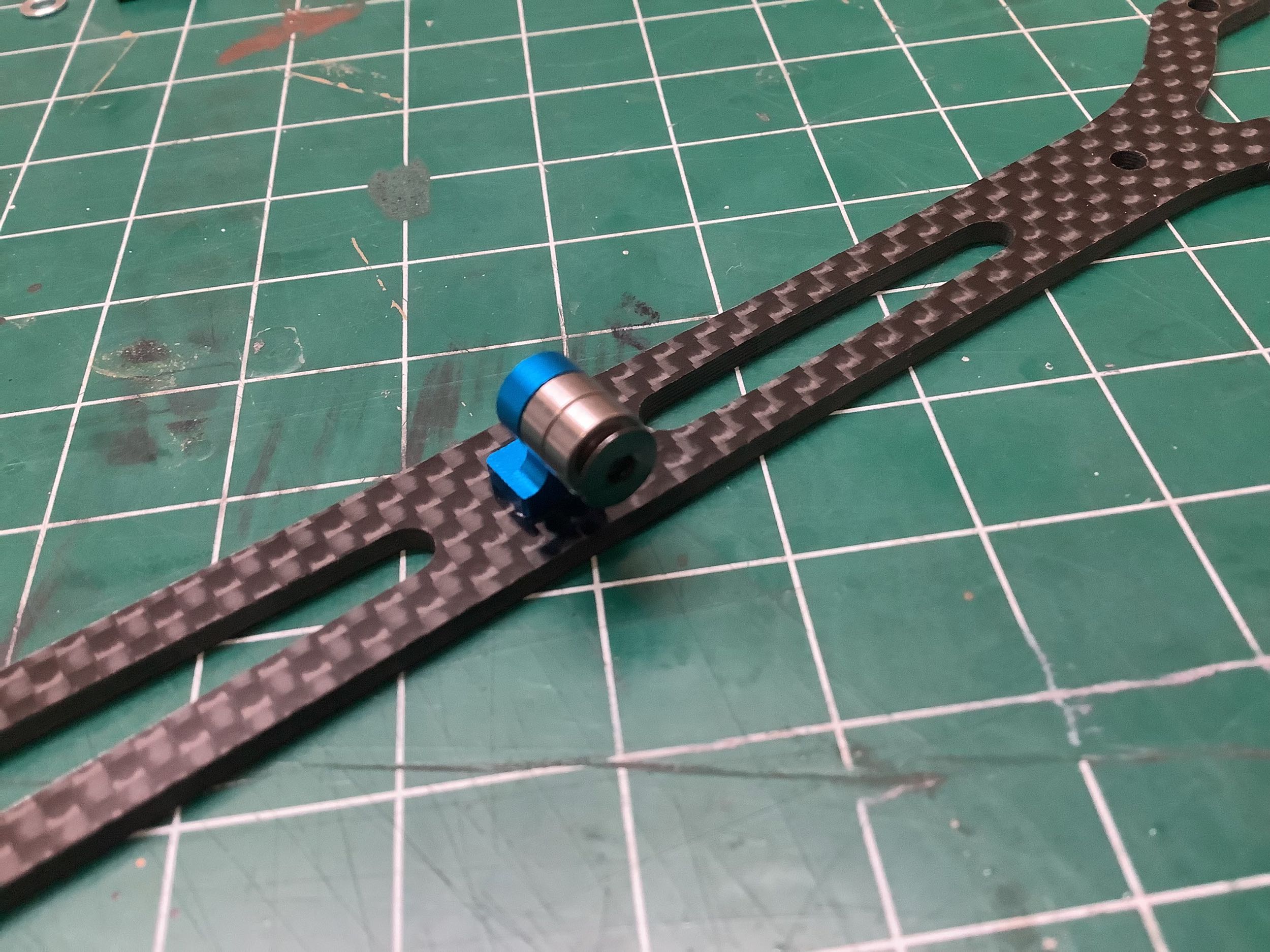
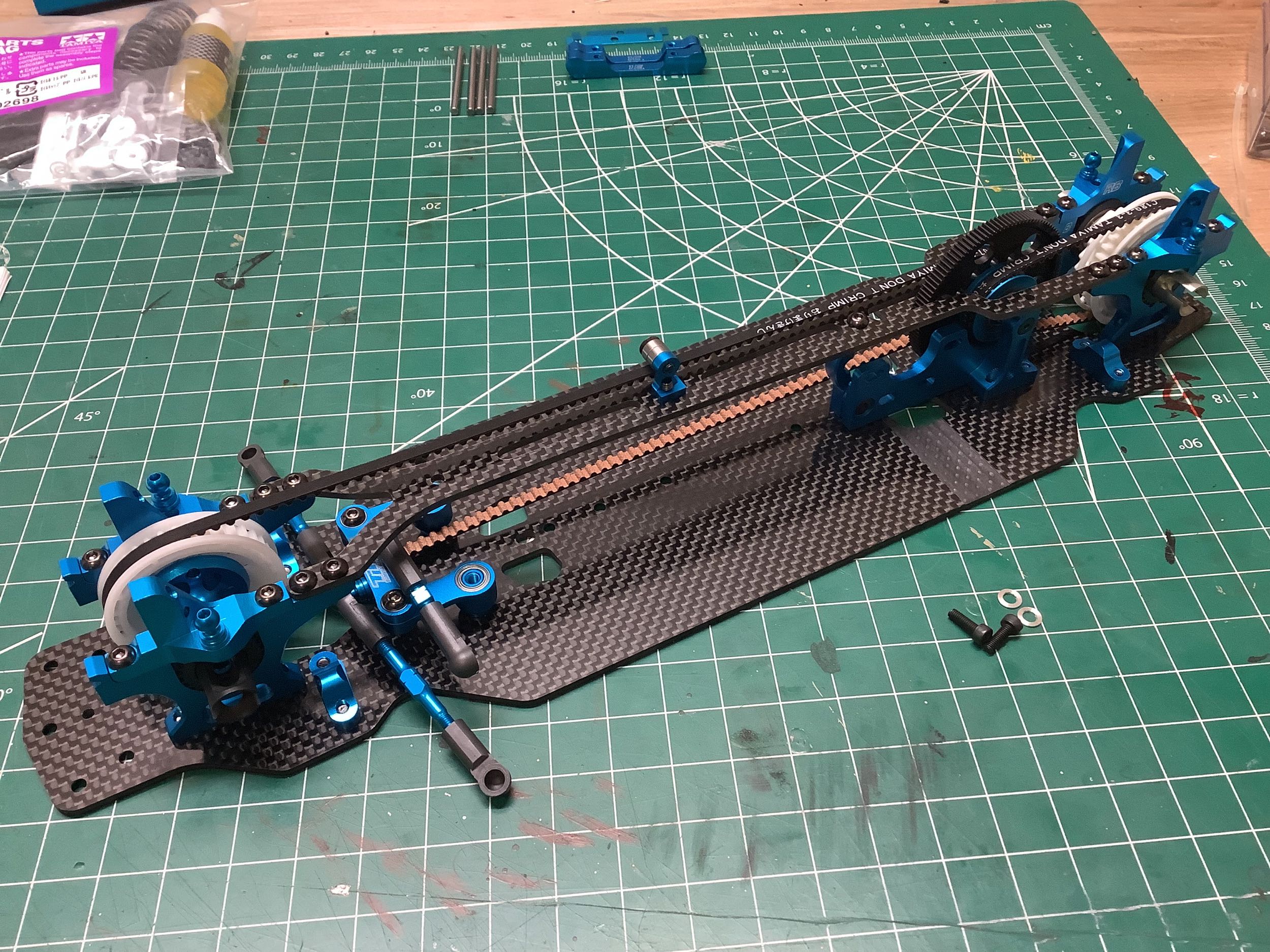
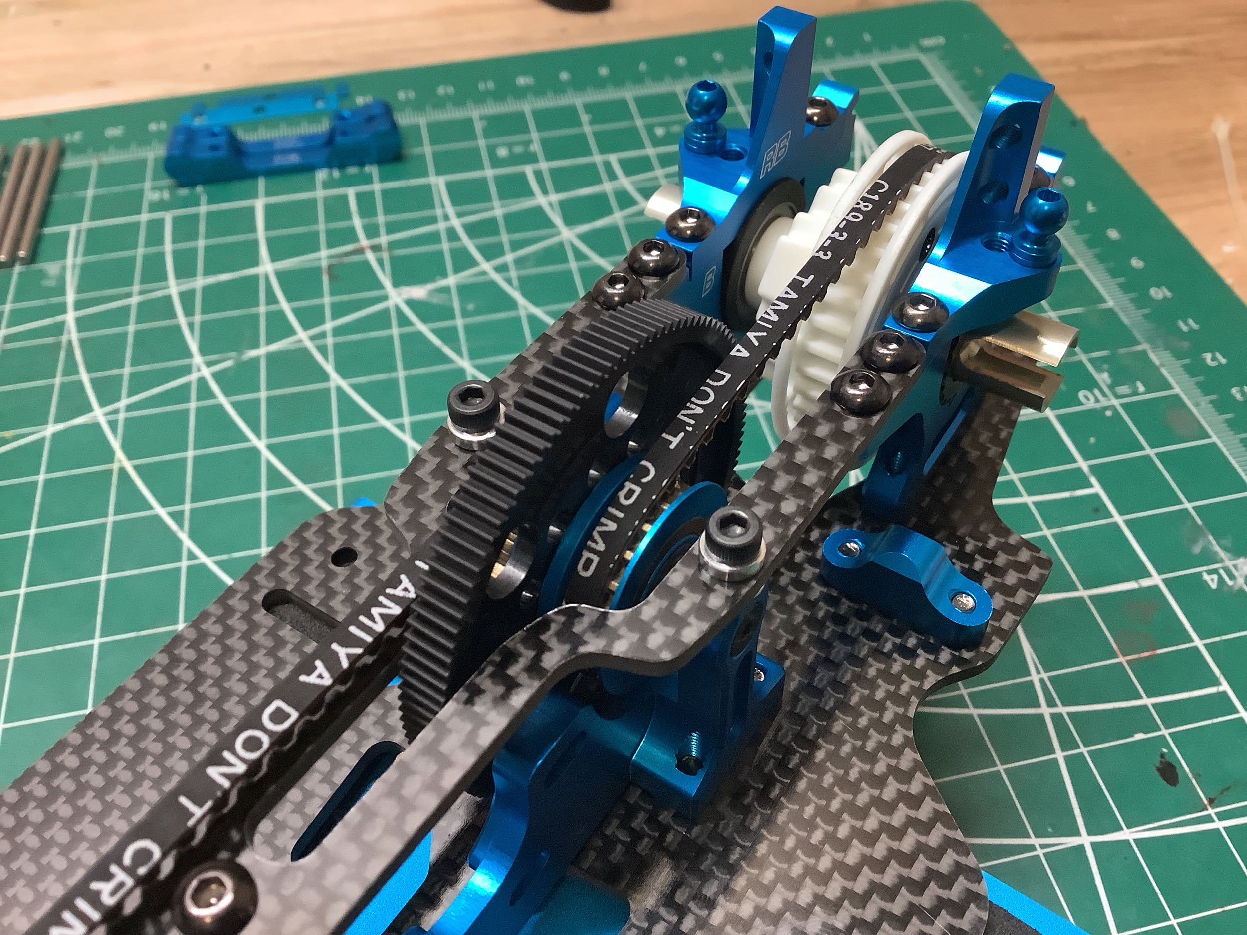
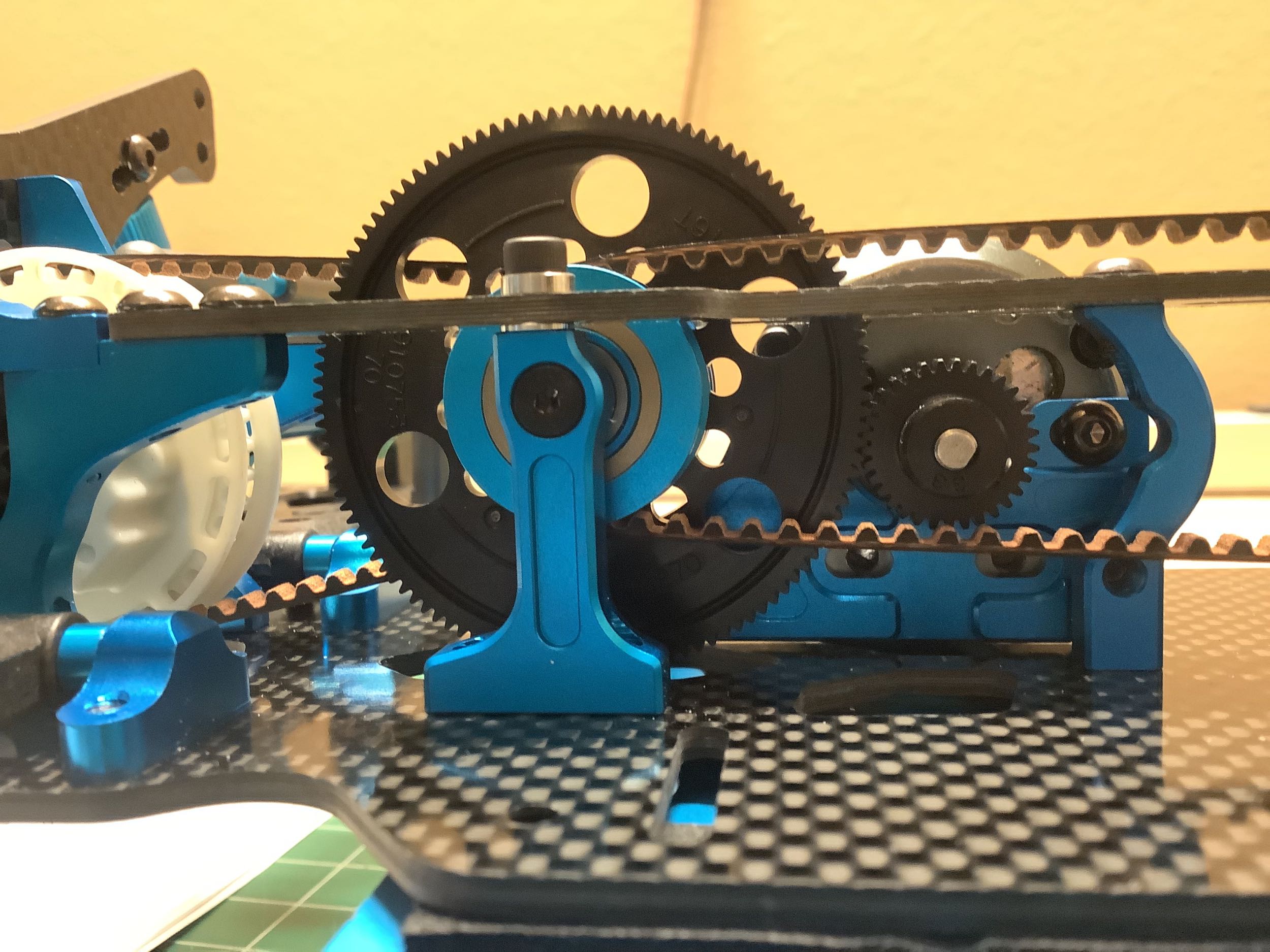
The center shaft now screws directly to the center bulkheads instead of
being retained by caps. This allows the top chassis deck to span
the center bulkhead without necessarily attaching to it (these screws
are optional) which allows the driver to tune the chassis
stiffness. The side view highlights how the eccentric cams can be
used to adjust the bearing tension.
The front axle uses a direct spool just like the TRF 417 series (no
differential, no one-way bearing). The drive cups have been
simplified though. Note that the front drive cups are steel while the rear are aluminum.
The steering bellcranks seem to change a bit with every generation, and
these are no exception. The changes don't appear to make any
relevant mechanical difference to me, but there must have been some
reason. The steering bridge appears to be the same geometry as
before except the TRF logo has been added. The blue turnbuckle
shafts and adjusters appear to be the same as they have been for a long
time.
The upper deck incorporates a set of bearings for belt support.
The one piece design spans all the way from the front to the rear
bulkheads.
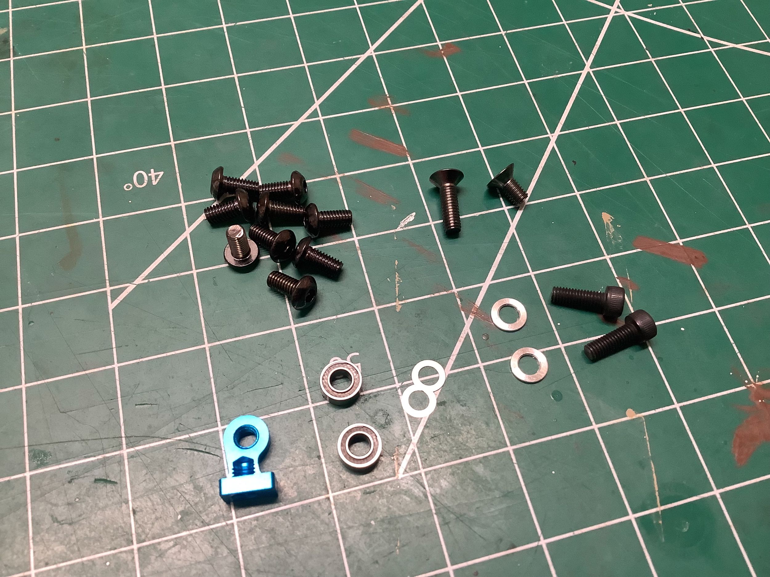
As mentioned previously, the driver can decide whether or not to attach
the upper deck to the center bulkhead (holes left open at left, screws added at right). Since I'm not going to be
driving mine anyway, I put screws in all the optional locations (see
socket head cap screws in the right hand photo). Note that the
screws called out in the instructions (2.6x8mm) are too long and will
interfere with the center shaft support screws preventing them from
being tightened completely. A manual correction page tells you to
use 1.5mm thick spacers under the screw heads as shown.
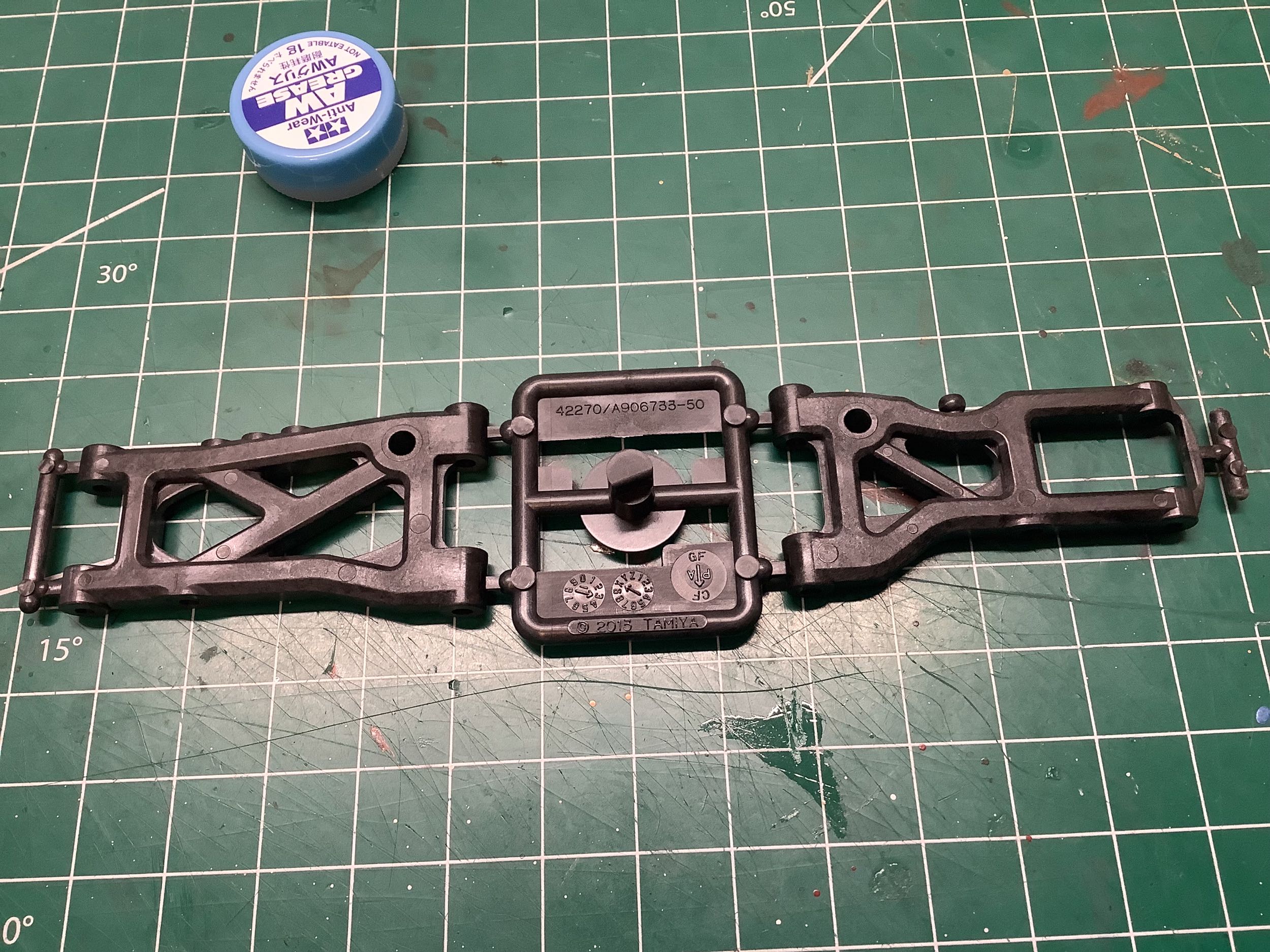
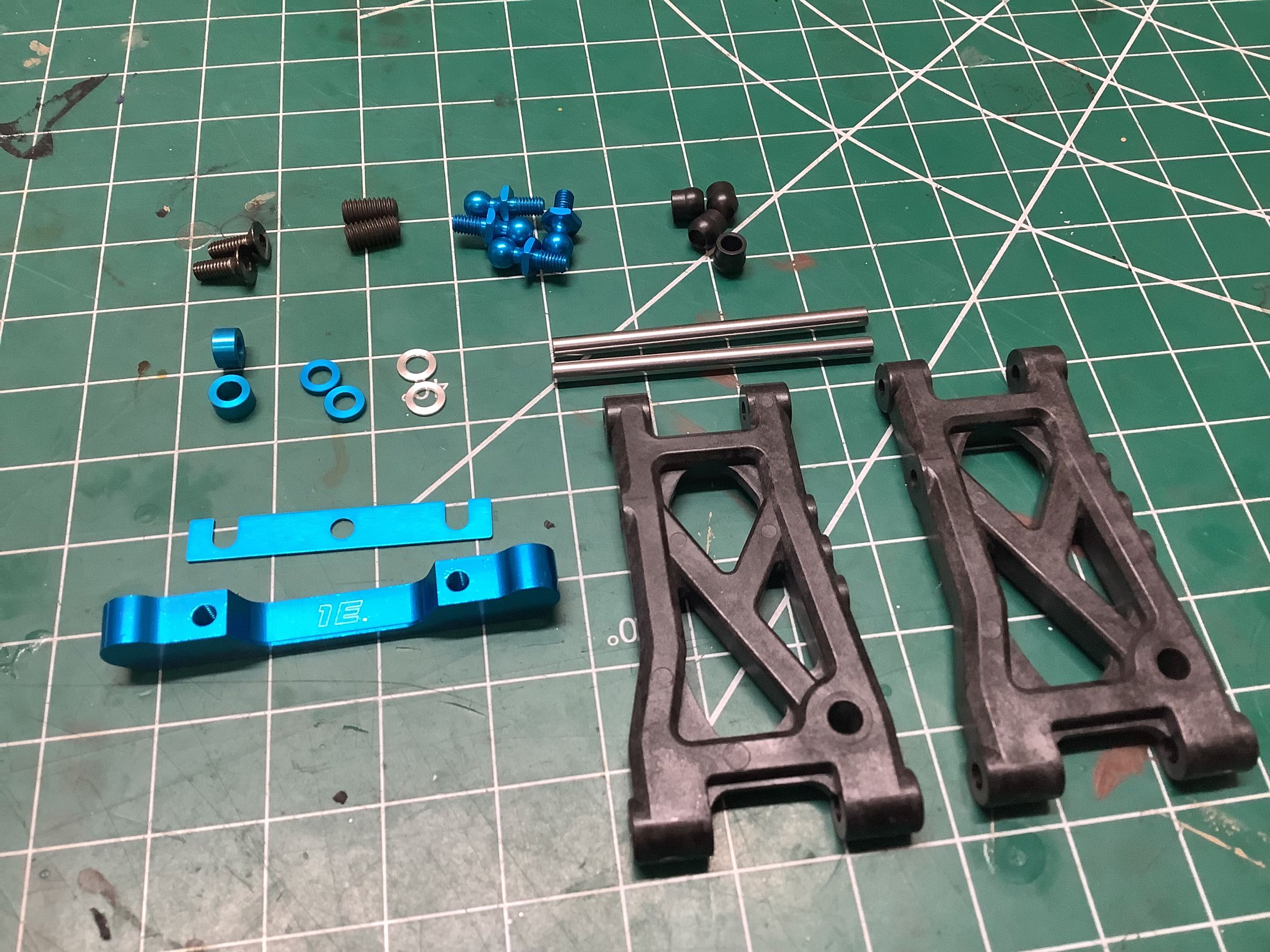
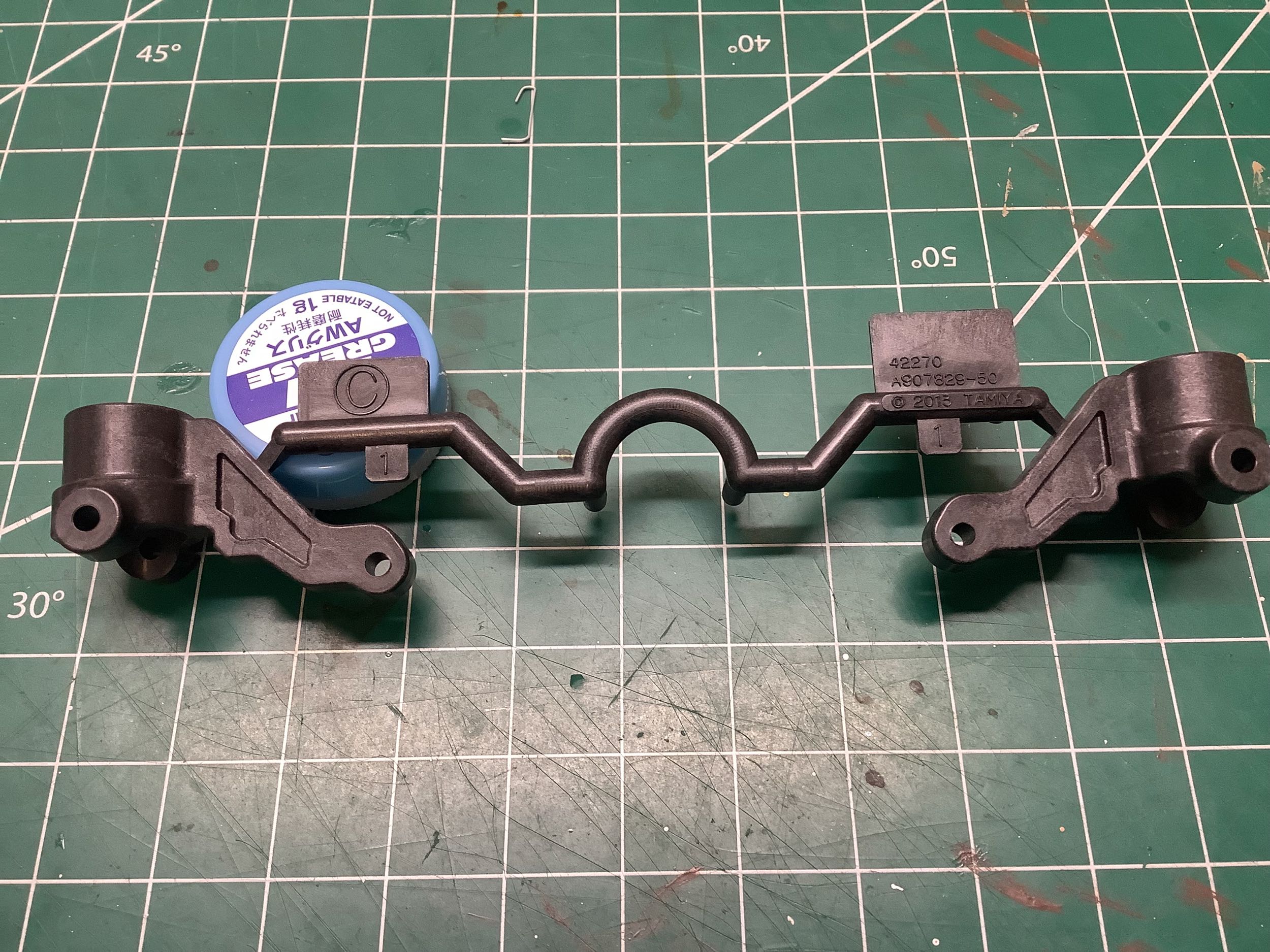
The suspension arms are new for the TRF 418. A close look will
show that these parts are marked with the model number 42270 and were
molded in October of 2013 from carbon filled polyamide (Nylon).
They are simpler than the old arms and no longer reversible. The
set screw which is used to adjust the down stop has increased from 3mm
to 4mm for more contact area with the carbon chassis plate. Note
that the TA-07 uses the same arms but they are glass filled (softer)
instead of carbon filled (harder).
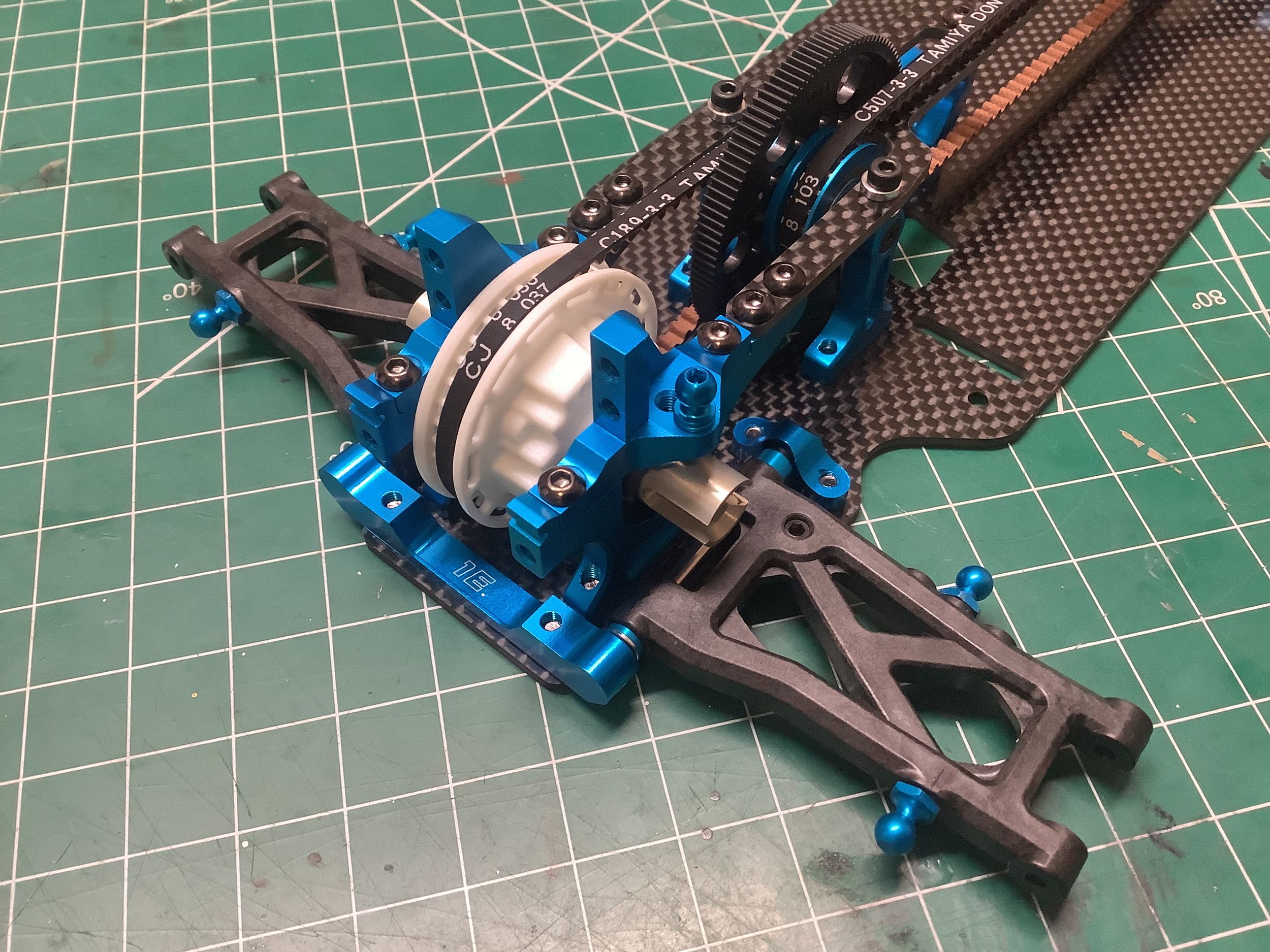
The rear lower suspension arms can now be installed. The hinge
pins are the same size as before (3x46mm) but no longer fluorine
coated. The rear suspension mount is a 1E which, in combination
with the 1XA forward mounts, results in a 3° rear toe angle. The
shocks will attach to the ball stud on the back side (no alternate
options) while the sway bar will attach to the ball stud on the front
side (3 options).
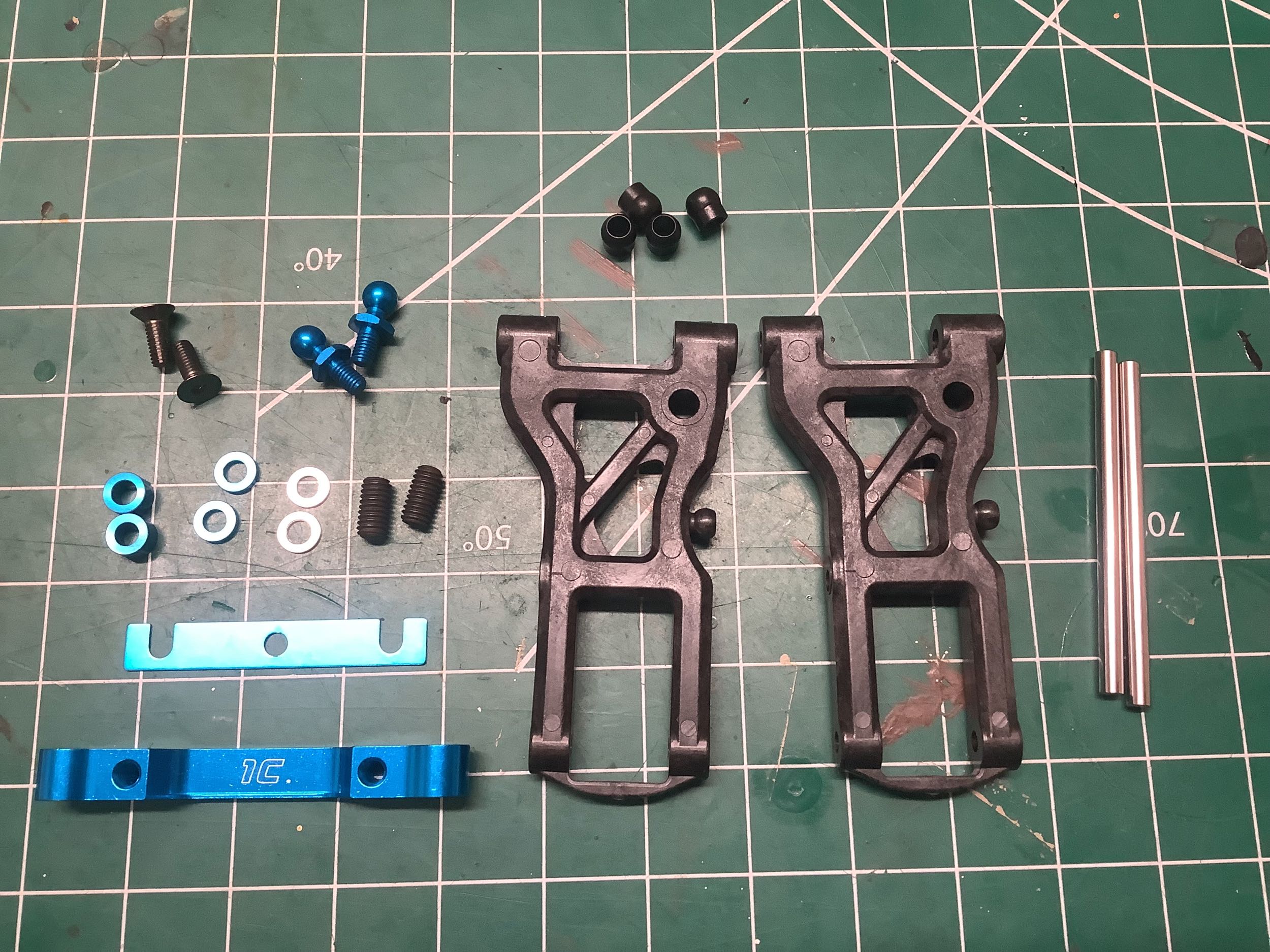
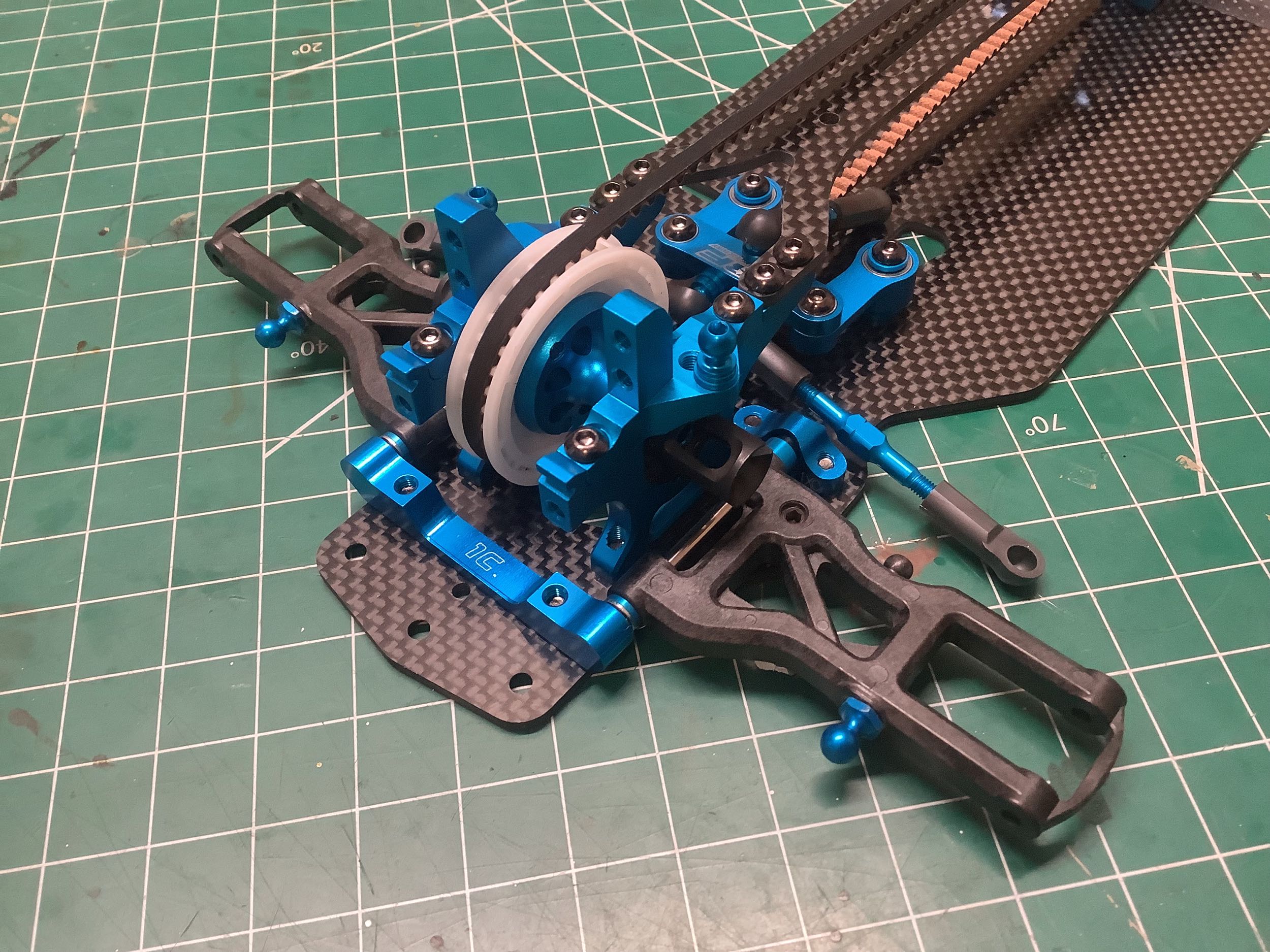
The front suspension arms have also been updated and simplified and use
the same hinge pins. The ball stud for the sway bar attachment is
molded right into the arm and is therefore not adjustable. The
ball stud for the shock attachment has only one location option.
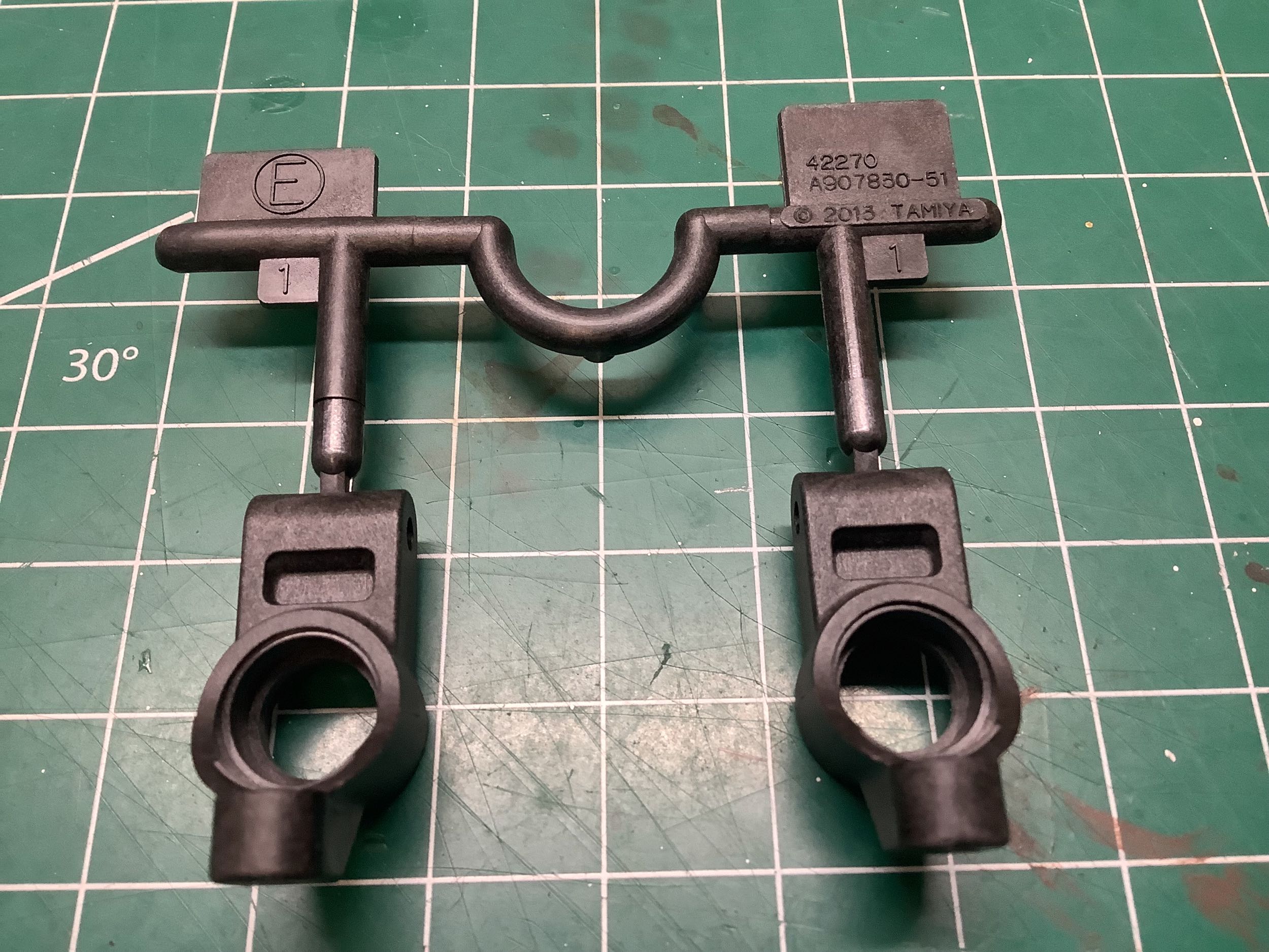
The rear uprights are also new for the TRF 418, though it is not very
obvious from looking at them what has been changed or why. Looks
like they now have only one option for camber link attachment but are
otherwise the same.
The rear uprights and CVD axles assemble just like they did on the TRF
417X with aluminum dogbones and steel axle shafts. The hinge pins
are still captured by a set screw.
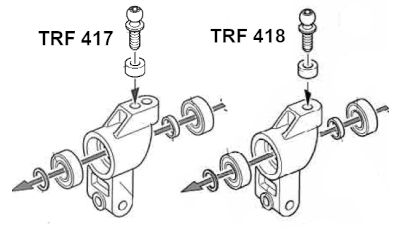
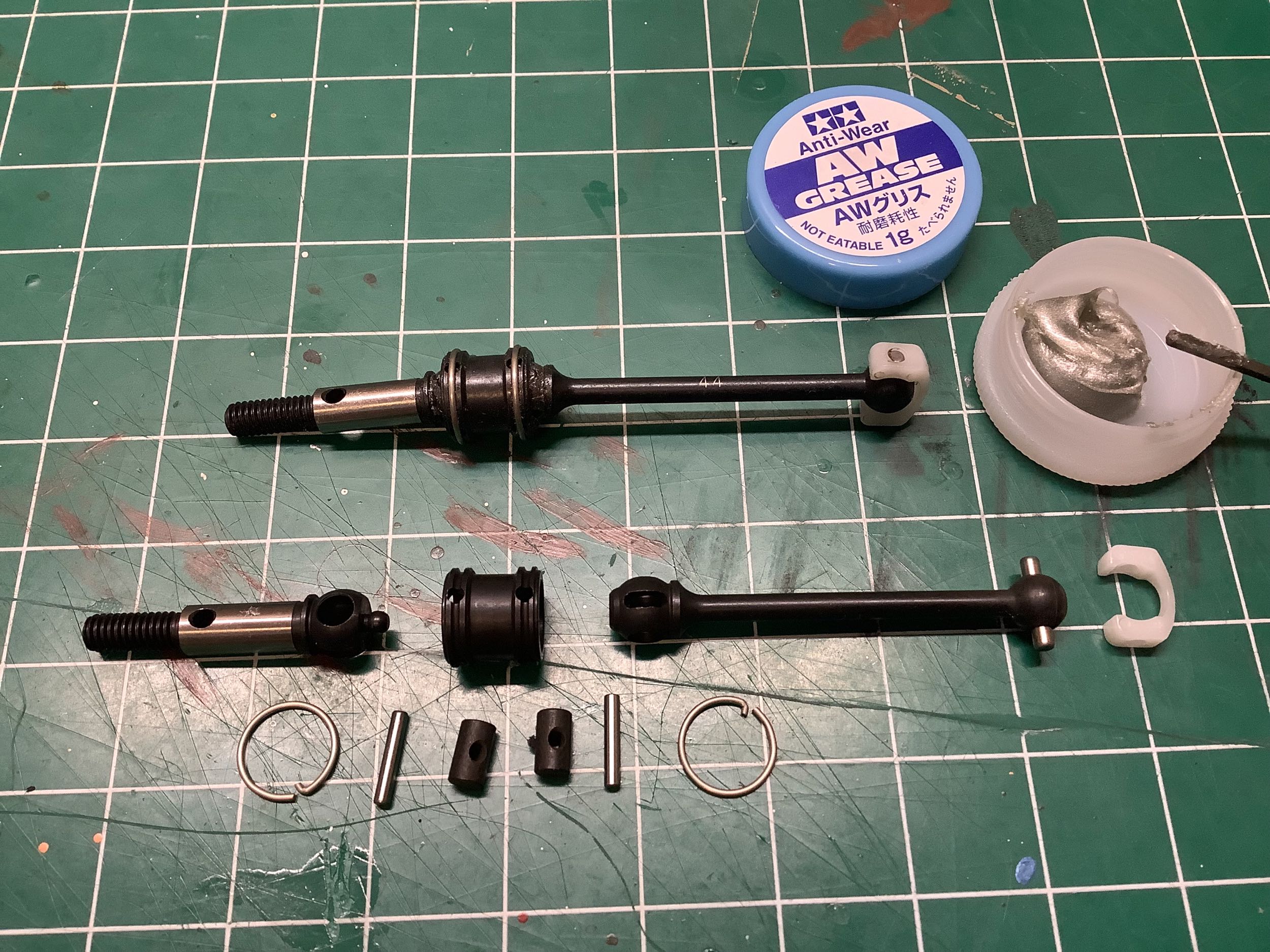
The front axles have changed to a double cardan type from the standard
CVD type on the TRF 417X. With two separate universal joints this
type can accommodate a larger steering angle without binding or
generating such a non-linear angular velocity. The design is
clever. To prevent all the angle from accumulating on one side of
the joint, a little tab on the end of the outboard axle fits into a
socket on the inboard axle. This keeps their centers aligned and
forces both sides of the joint to share half of the overall angle.
The dogbones are now steel instead of aluminum in the front (rear are
still aluminum). Note that this design was introduced with the TRF
417 V5 and carried forward here.
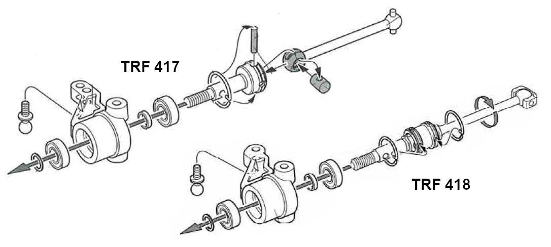
The steering hubs are also new for the TRF 418, and again the changes
are pretty subtle. An overlay tells me that the new hubs are almost the
same except the steering link stud hole has been moved slightly inboard
for more Ackerman. You can also see the addition of the new more
complex double cardan axles in the image on the right. You might
assume that the inner diameter of the hubs would have been increased to
make more room for the double cardan joints, but I can't see any
evidence of that.
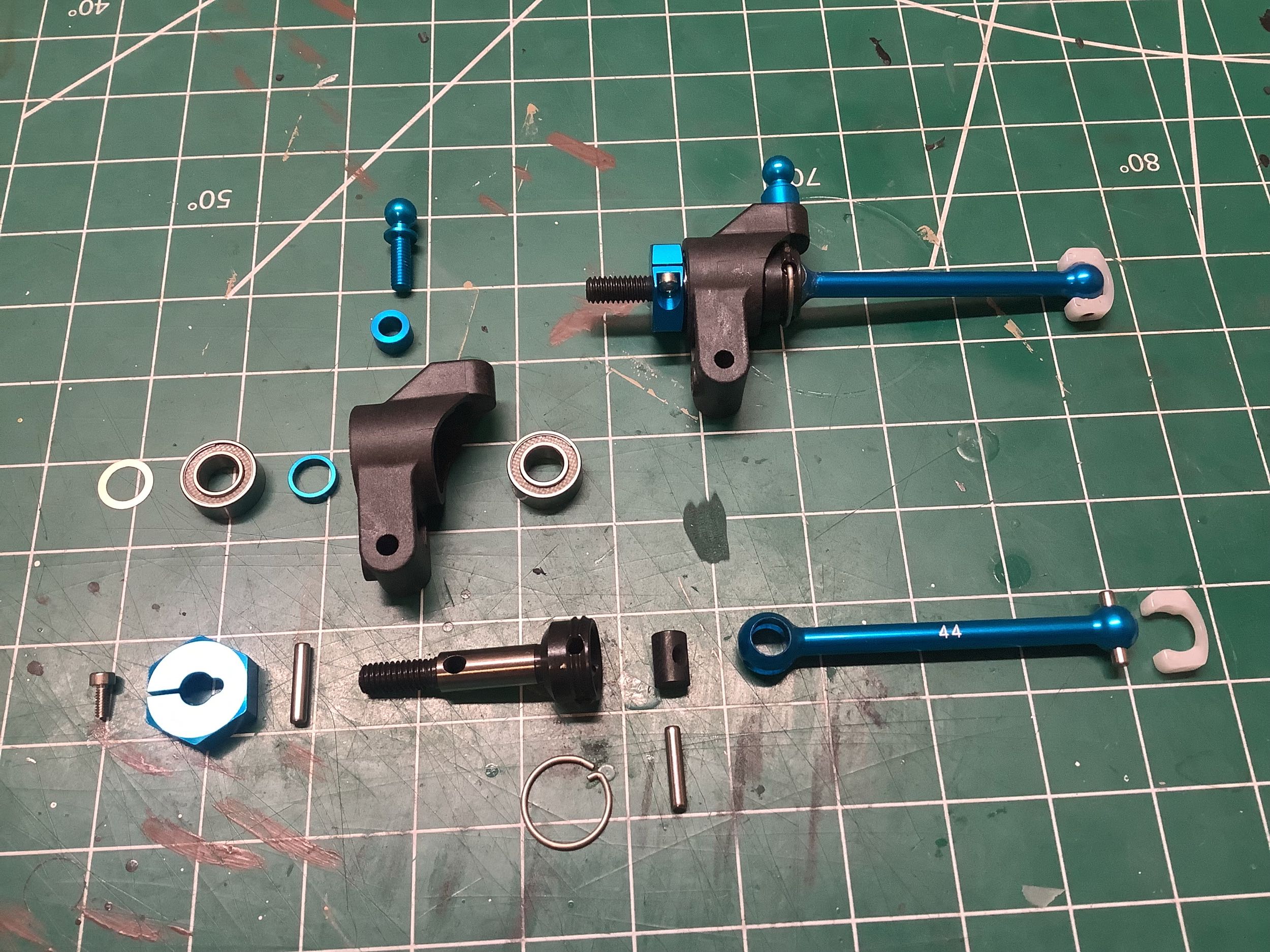
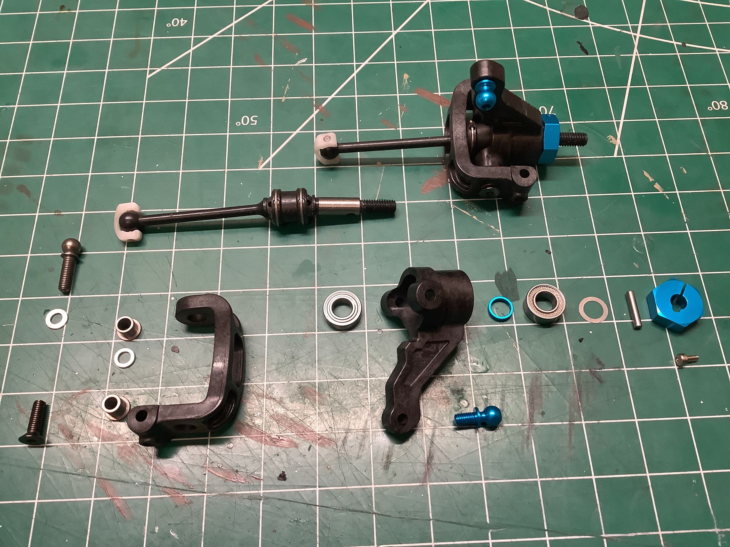
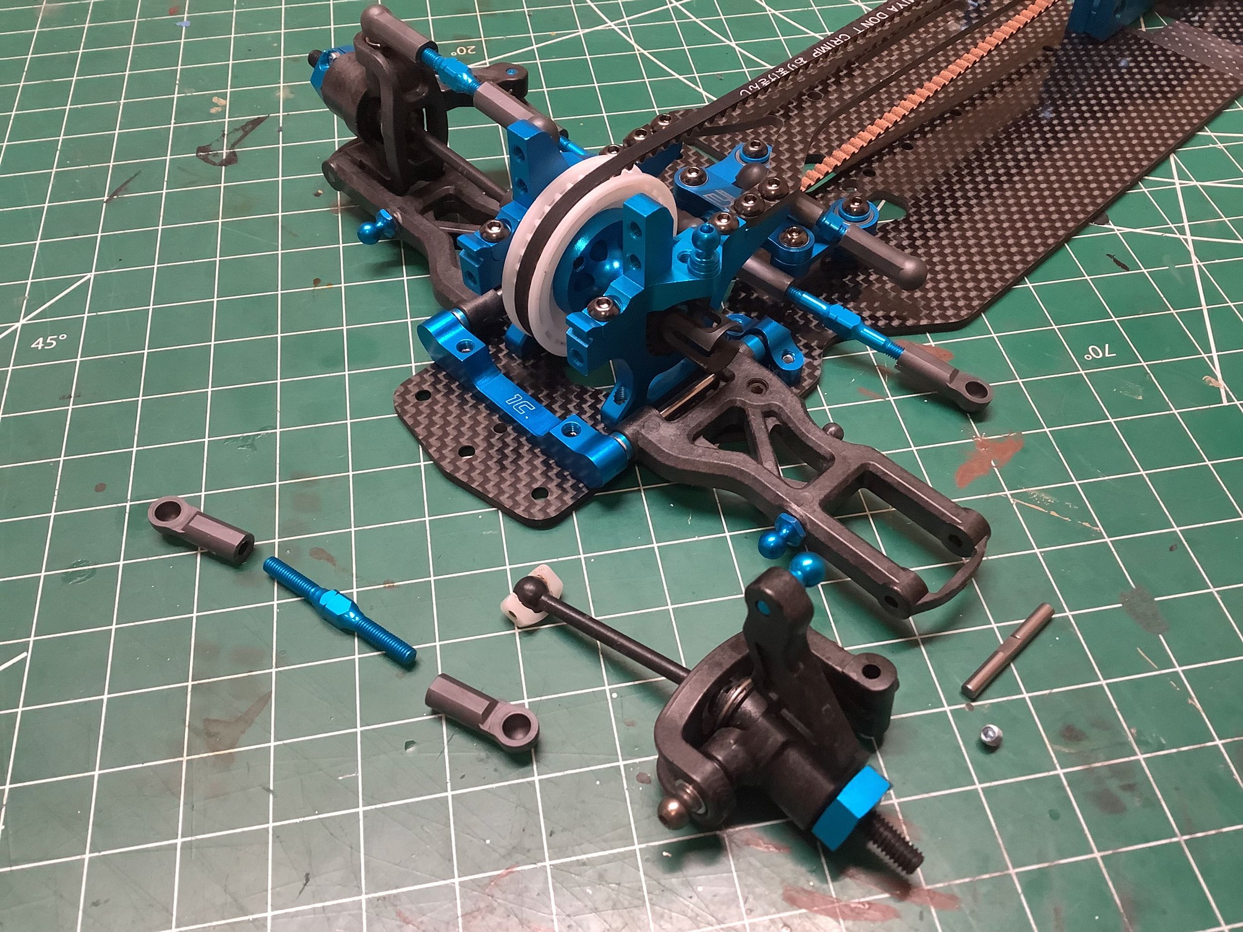
There are a lot of parts associated with the front steering and
suspension assemblies. The C-hubs (F parts) have a 4° caster angle
and seem to be unchanged from the TRF 417. The confusing sized
flanged bushings (4.5x3.5mm and 4.6x4.7mm) are unfortunately also
unchanged.
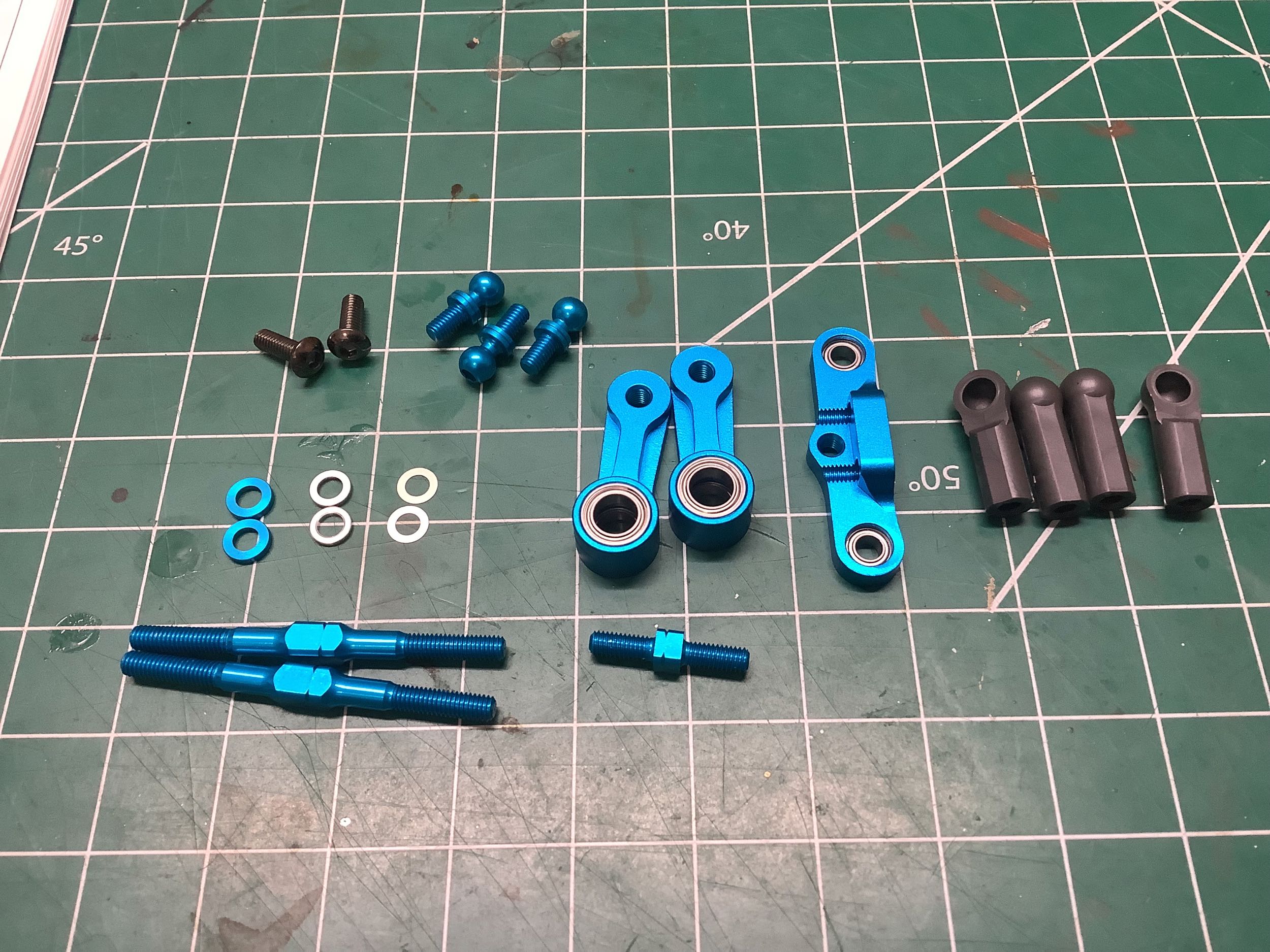
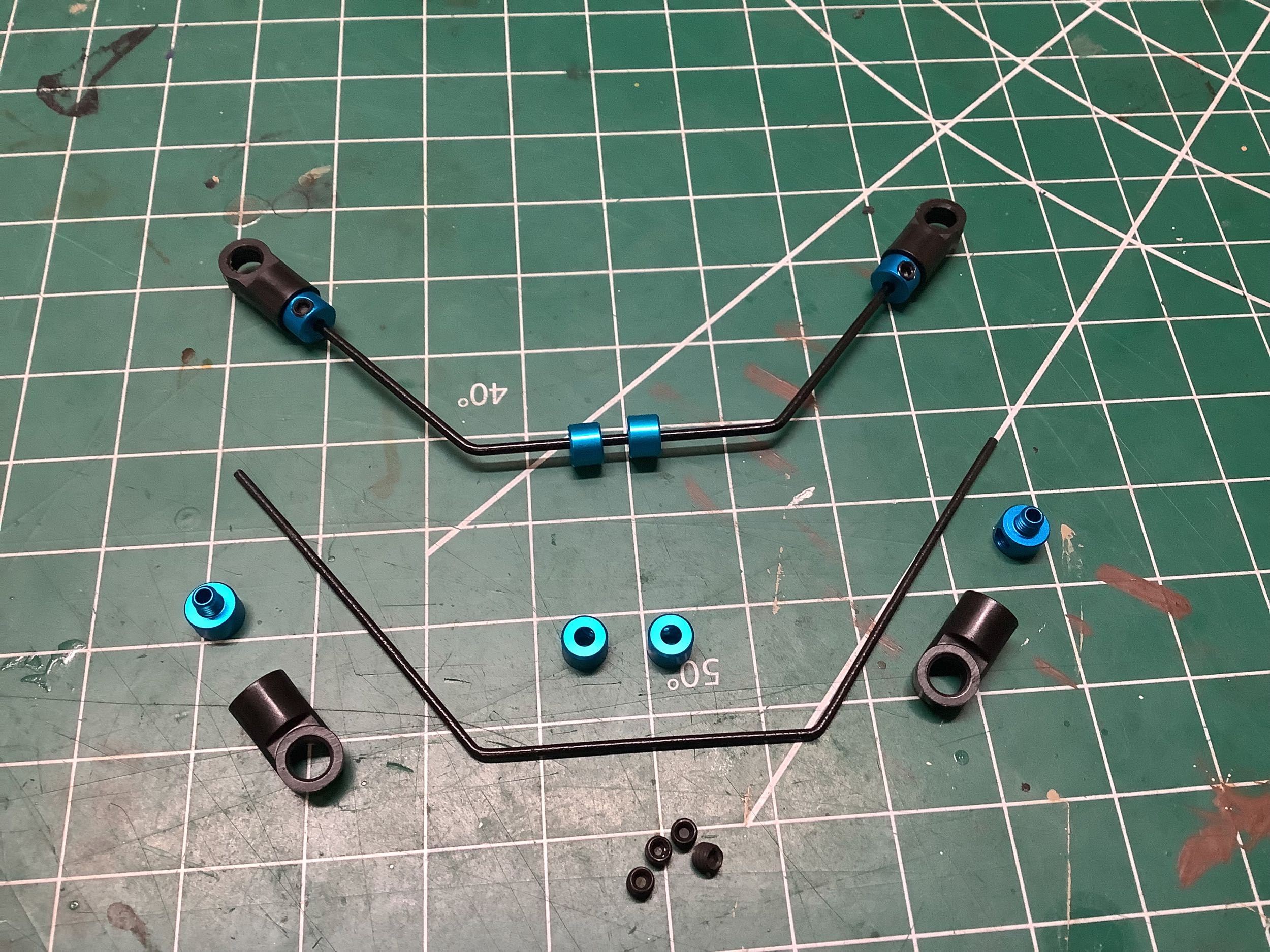
The sway bar assembly has been subtly altered from that used on the TRF
417. The 417 used aluminum ball joints on the ends of the bars,
while the 418 now uses plastic ball cups instead which thread onto
aluminum retainers. This means the aluminum ball joints have moved
onto the mating rods instead. I'm not sure why this is any
better, but it's different. The rear sway bar is soft stiffness
and the front is medium. It is interesting the note, however, that
the range of stiffnesses available is different for the front and
rear. The rear sway bar options vary from 1.1mm - 1.3mm diameter,
so the soft version in the kit is 1.1mm. The front sway bar
options vary from 1.3mm - 1.5mm diameter, so the medium version in the
kit is 1.4mm. These are the same geometry as those used on the TRF
417 so they are backwards compatible with that line.
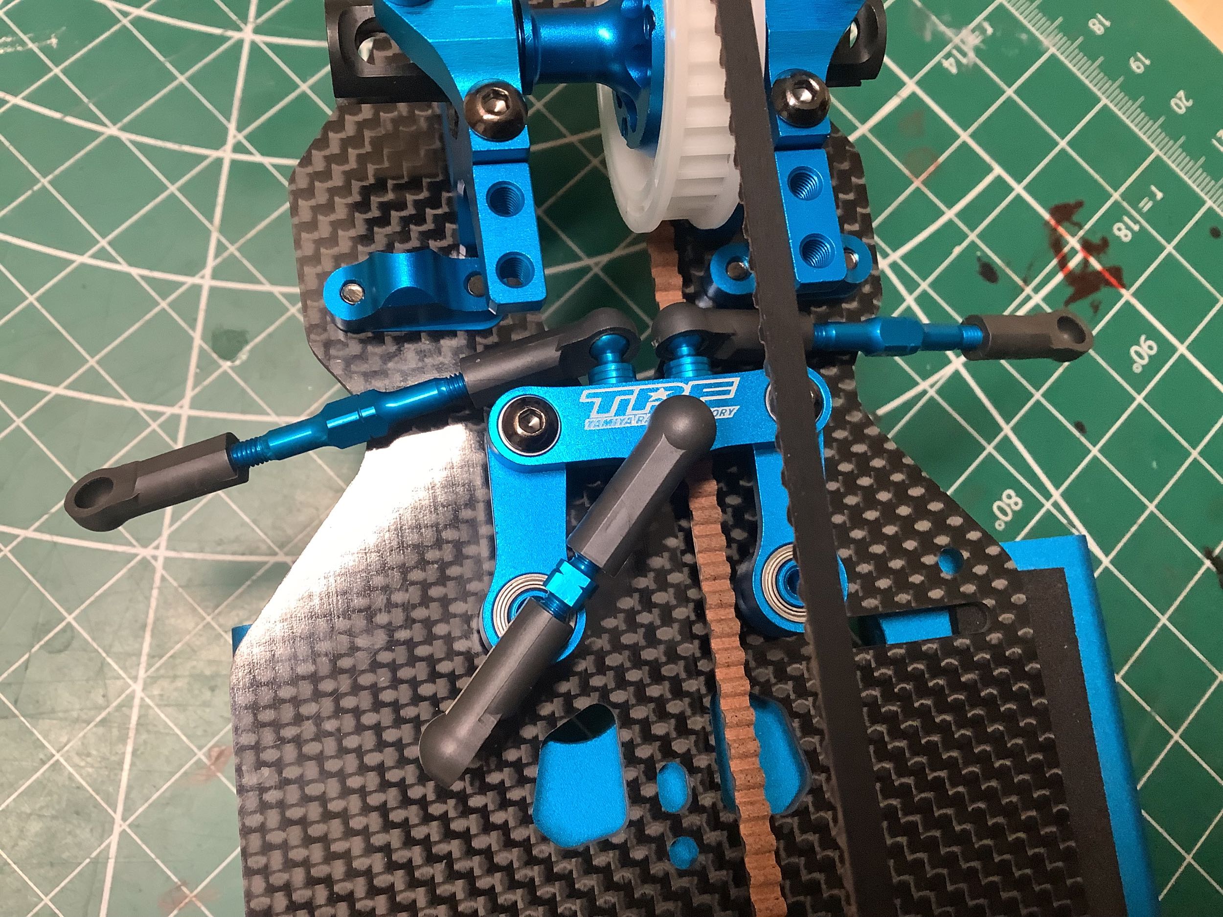
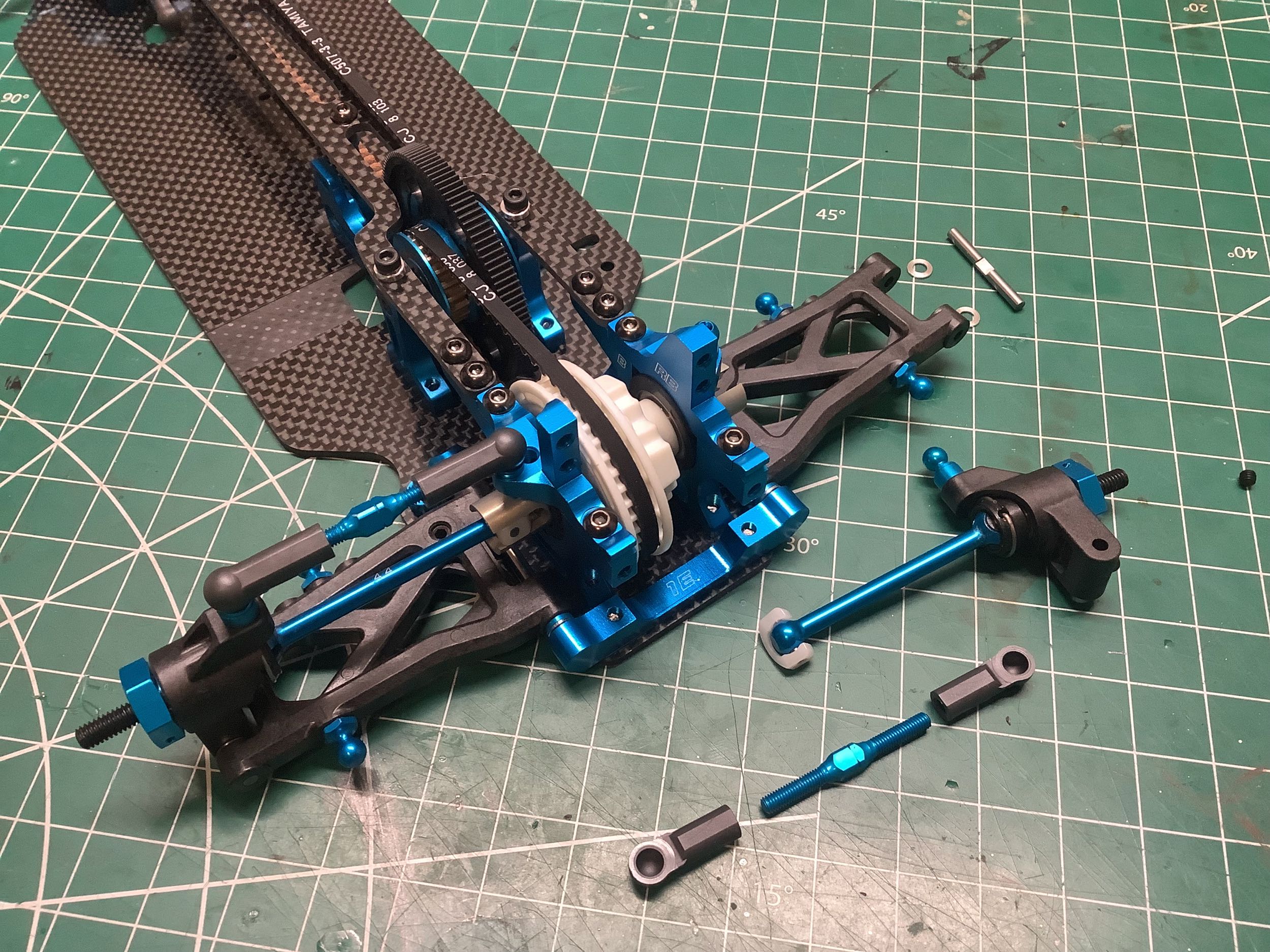
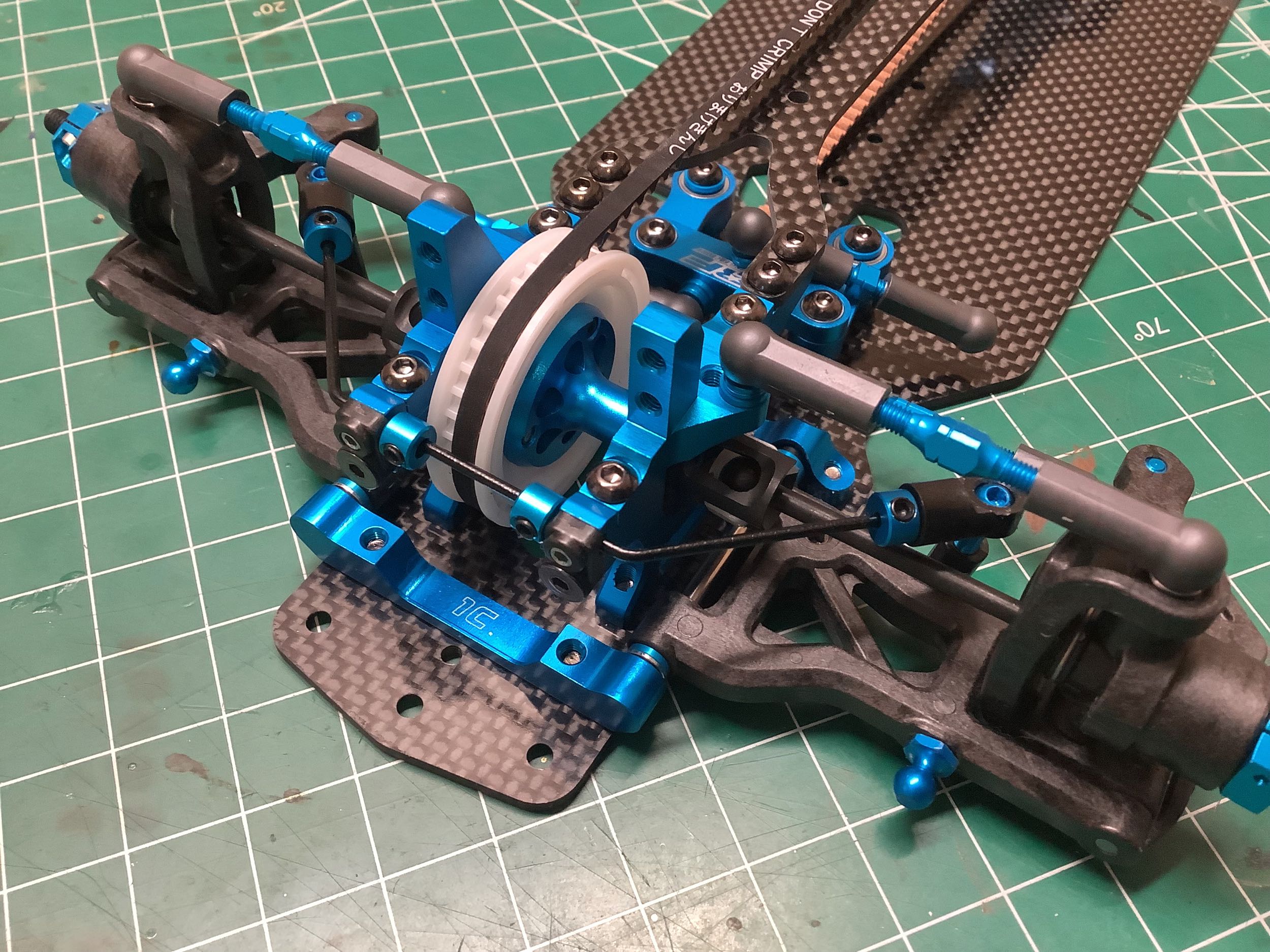
Here you can see the front (left) and rear (right) suspension assemblies
with the sway bars installed. If you look closely you can see the
vertical blue ball ends connecting the bars to the lower arms. To
me it seems like vertical motion would be more likely to pop these ball
out of the cups which seems worse, but what do I know. The
advantage is probably that the length of the old links was adjusted via a
hard-to-access turnbuckle while the new links can be adjusted by
inserting a 2mm hex driver through the open ball cup from above.
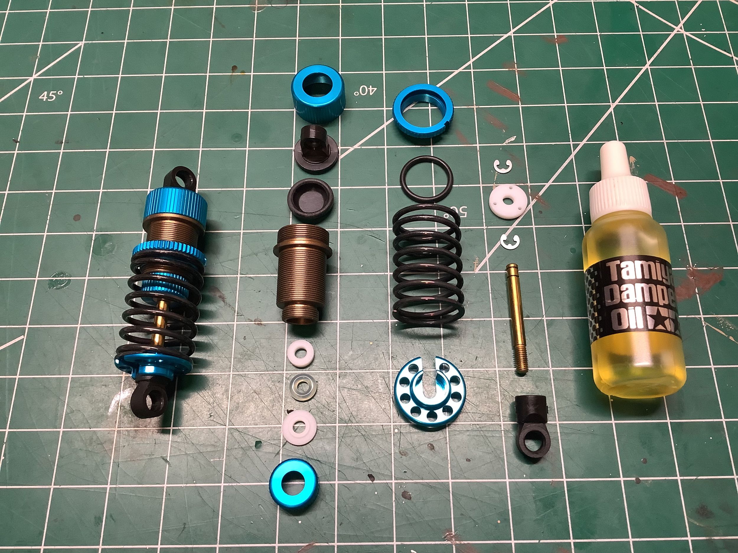
The TRF 417X used the "standard" 55mm perfect TRF shocks with Tamiya's
HL (High Lubrication) coating on the cylinders, Delrin pistons, and
fluorine coated rods. The TRF 417 V5 did something new and changed
to aeration dampers with entrained air instead of a volume compensation
bladder. These had a different cylinder with a hex end, different
seal configuration (2 o-rings), and different caps and rod end (V
parts). While this style came from and continued to be used on
the TRF buggy line, the TRF 418 reverted to the standard bladder
type. Not all was identical though. While the 418 used the
same aluminum shocks and coatings as the 417, a new aluminum spring
perch was added to accommodate the new slightly larger diameter (+1.2mm)
springs. I never would have noticed the diameter difference
looking at the springs and only found out about it by trying to figure
out why the spare parts were different.
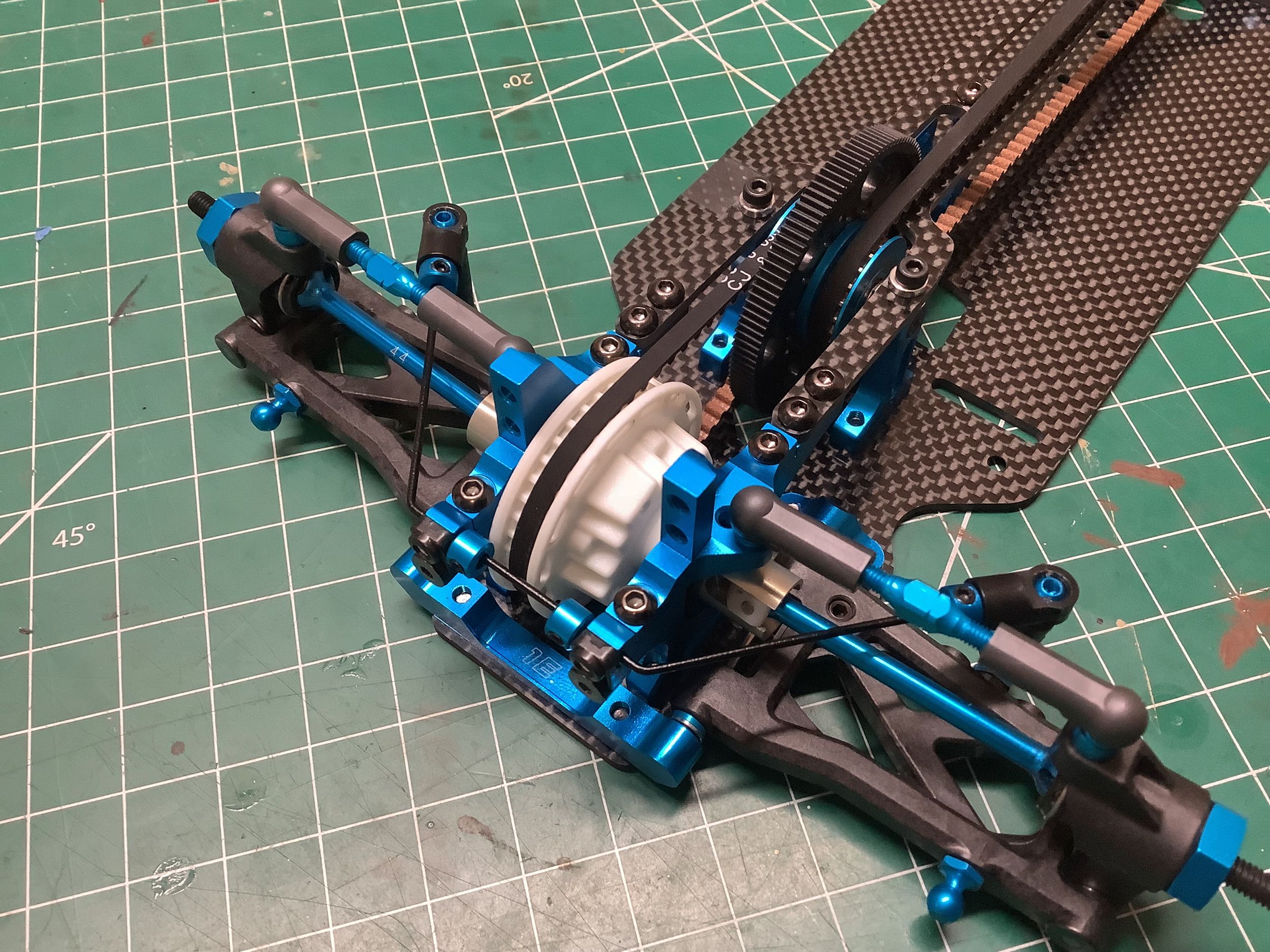
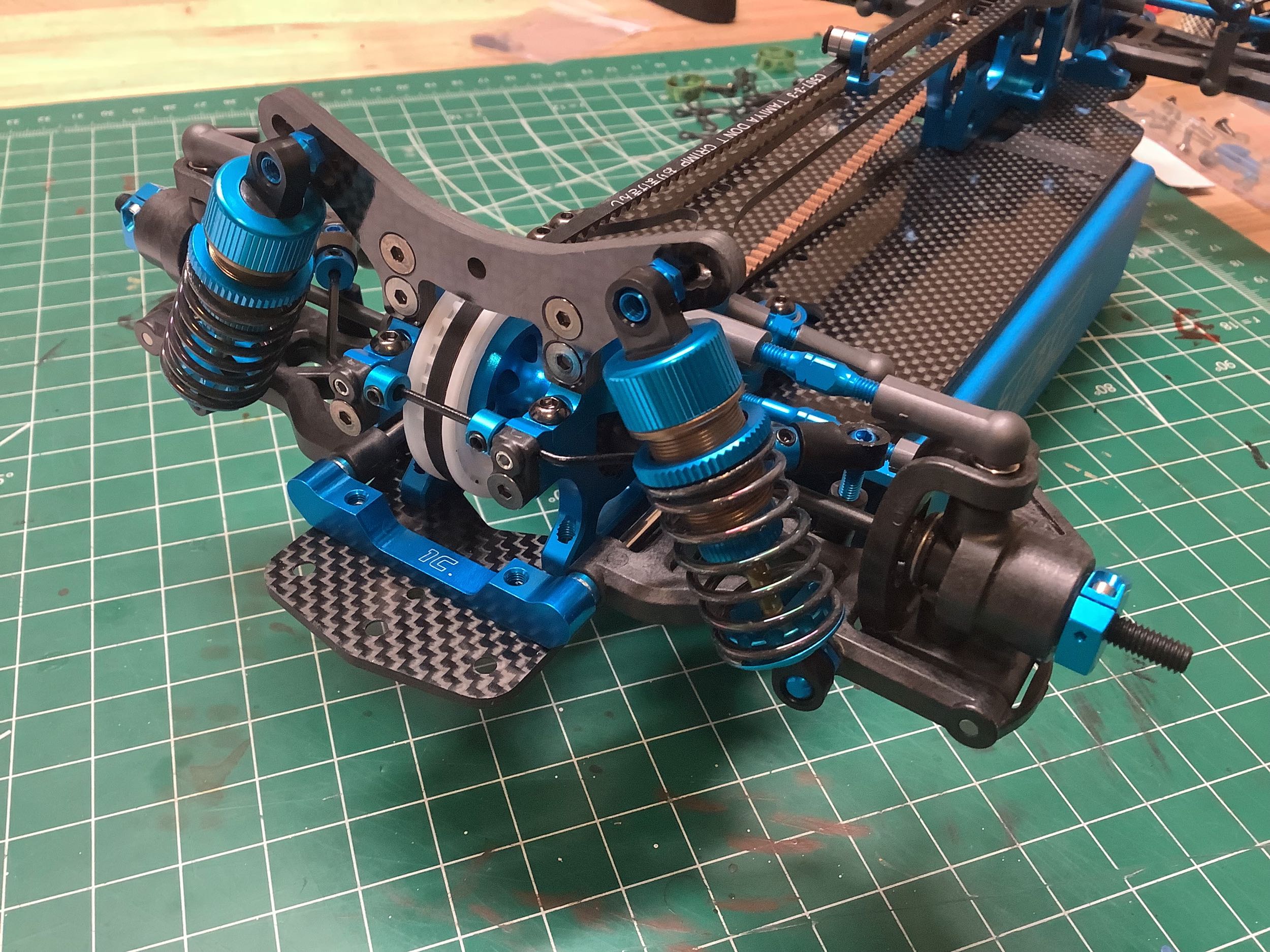
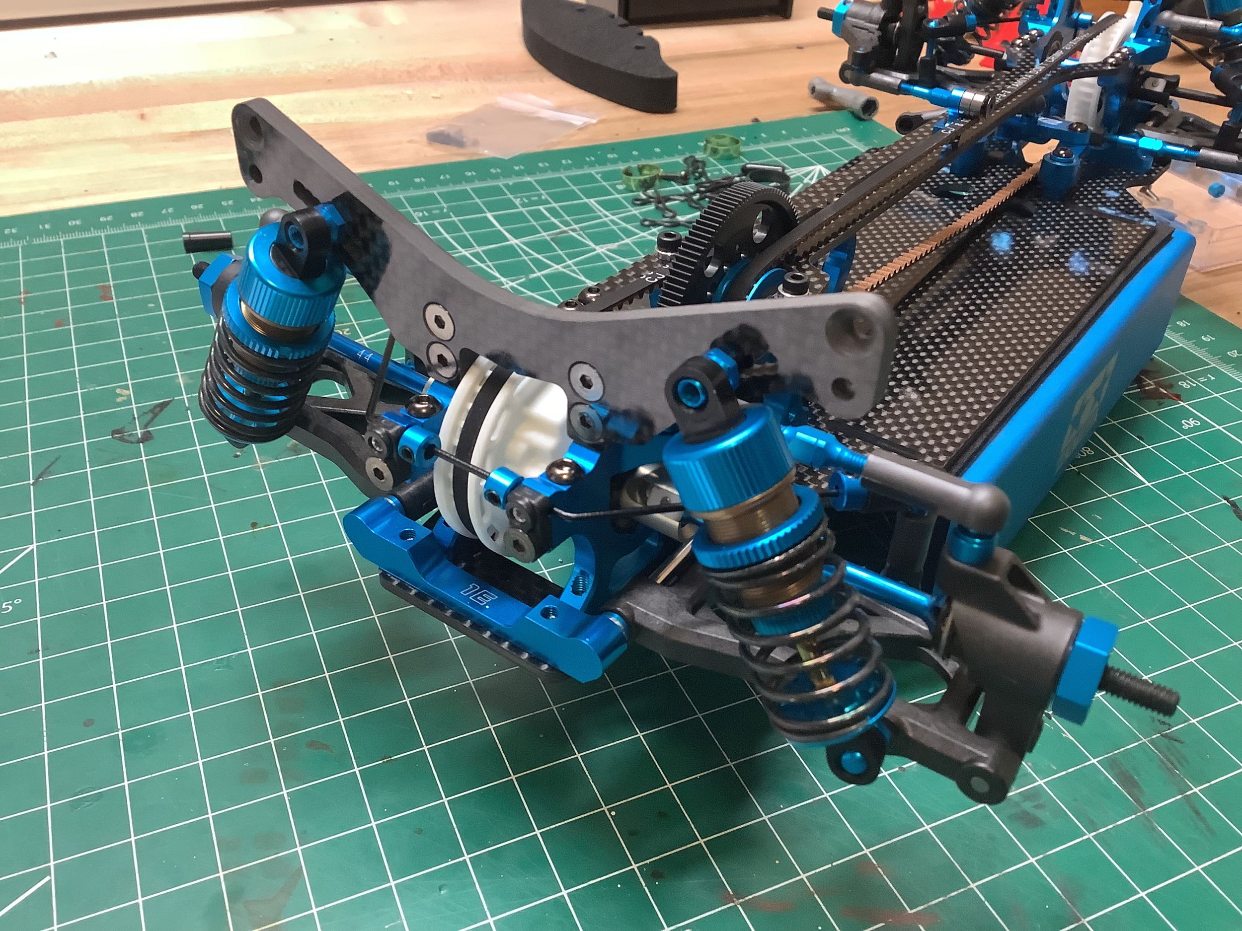
Here the dampers have been installed on the front and rear suspension
assemblies. Like always, the carbon shock towers are new even
though they are extremely similar to those from the TRF 417. The
most obvious visual difference is that the body post mounting holes are
now countersunk. While the shock mounting positions are the same,
the body post holes are also a bit lower.
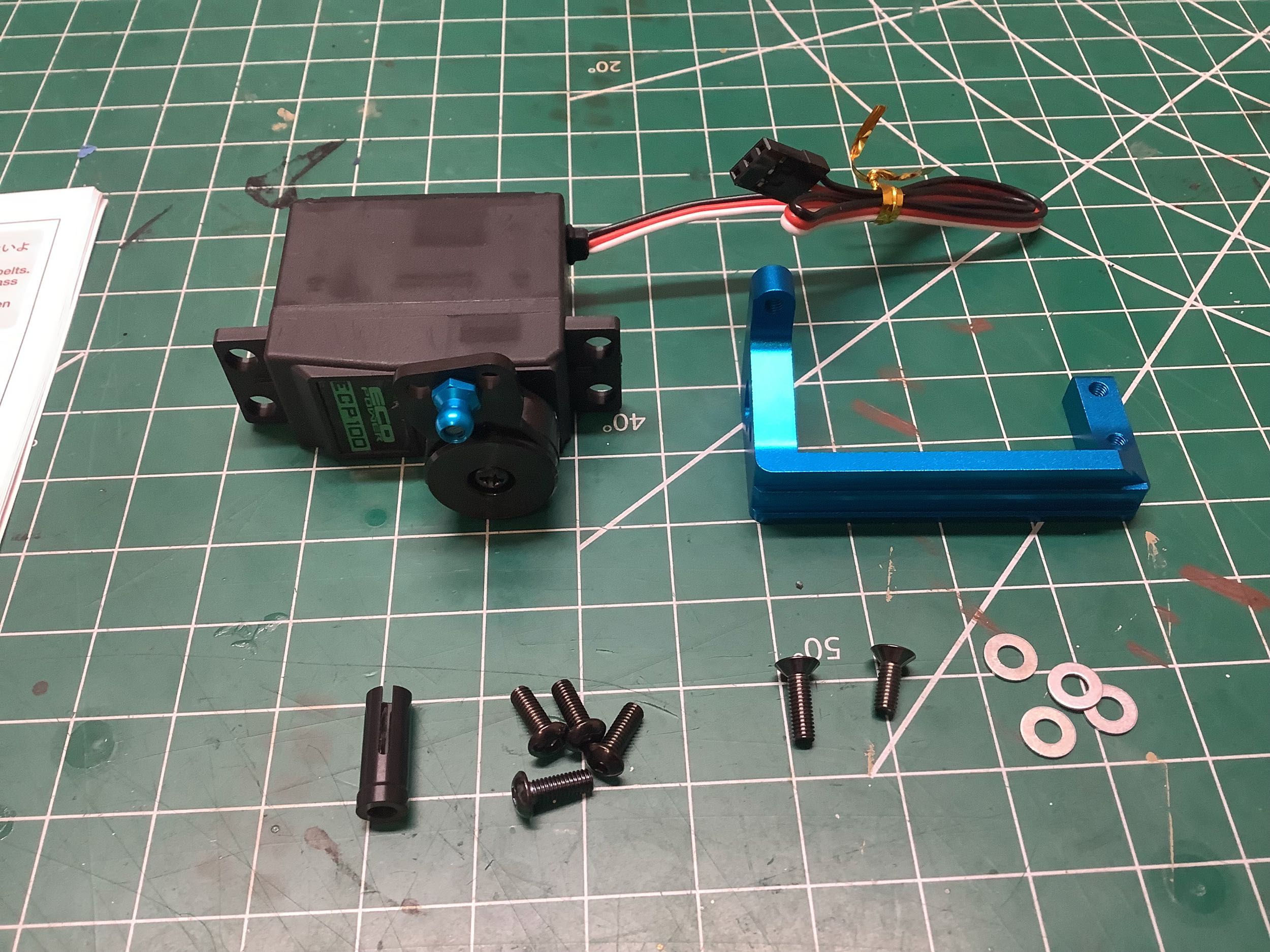
The method of mounting the servo has changed considerably. A
traditional setup just uses L-brackets on each end of the servo and
bolted to the chassis. This new style aluminum bracket spans the whole
servo and supports it from above but is only attached to the chassis at
one end. This results in a floating servo that does not serve to
stiffen the chassis, but is also somewhat less secure. It would
probably be a bad idea for a buggy which sees a lot of impacts, but
seems to work for touring cars and has become the standard since.
Note that this actually started with the TRF 417 V5. This chassis
works best with a low profile servo to leave room for the electronics,
but since I wasn't using any electronics I just installed a standard
servo.
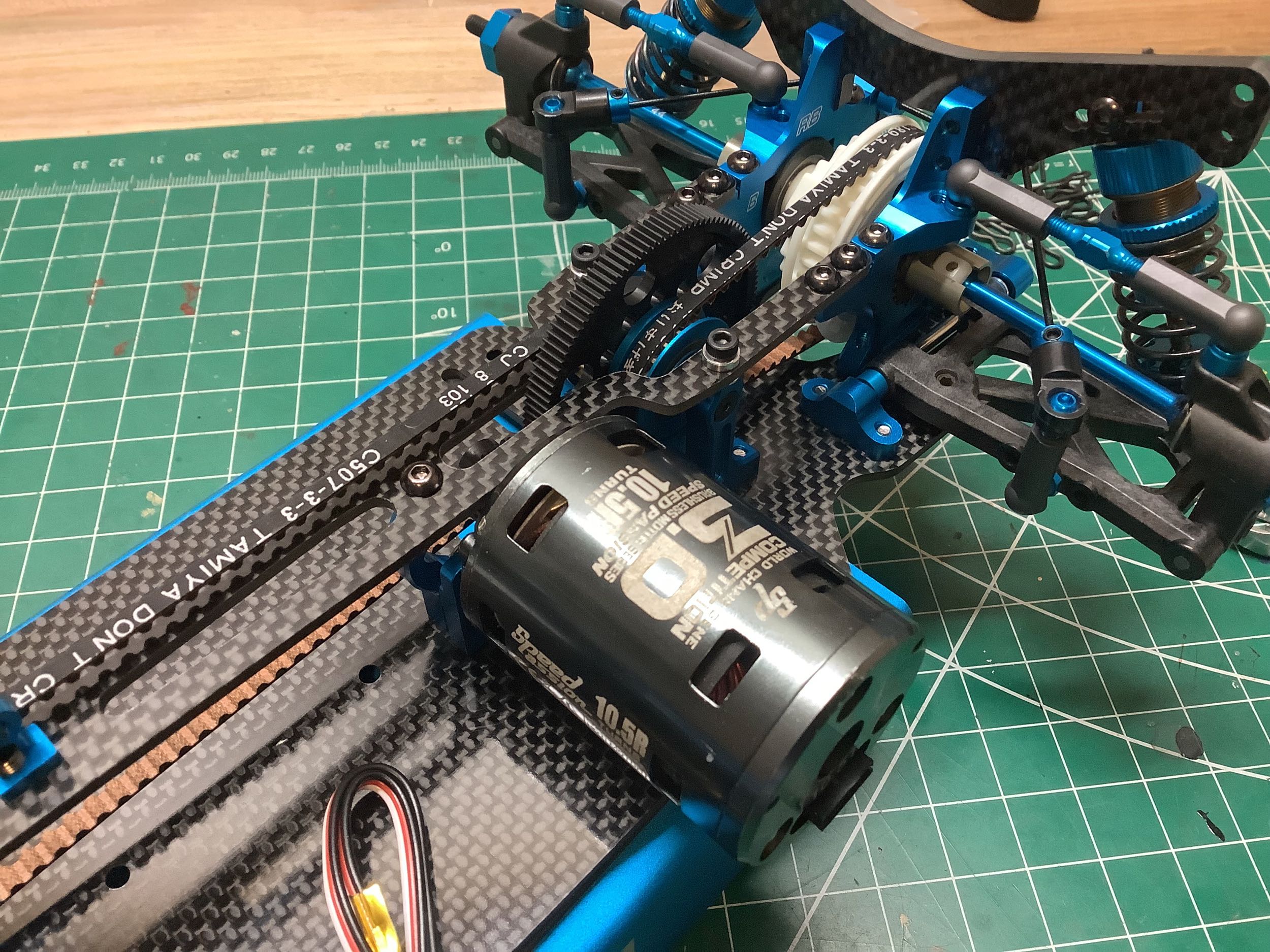
I used an old Speed Passion brushless motor just for display here.
Standard silver can motors won't fit. The side view shown on the
right highlights the new style of motor mount which doesn't go all the
way around the can but is only half height. Unlike brushed motors
which typically mount with 2 screws 180° apart, brushless motors
typically have 6 holes arranged 60° apart which allows more mounting
options. In this case, the upper diametrically opposed holes can
be used like normal (which is what I have done), or two adjacent holes
on the bottom could be used instead. Note that to access the aft
motor hole, you actually have go through a hole in the spur gear with
your tool. Using the bottom holes would avoid this. All of
the motor mount holes are slotted allowing the motor to be adjusted
fore-aft for different pinion sizes. With the kit standard 116T
spur, a huge range of 24T - 37T pinions can be used. By using the
optional 111T spur, it is possible to go all the way to 42T.
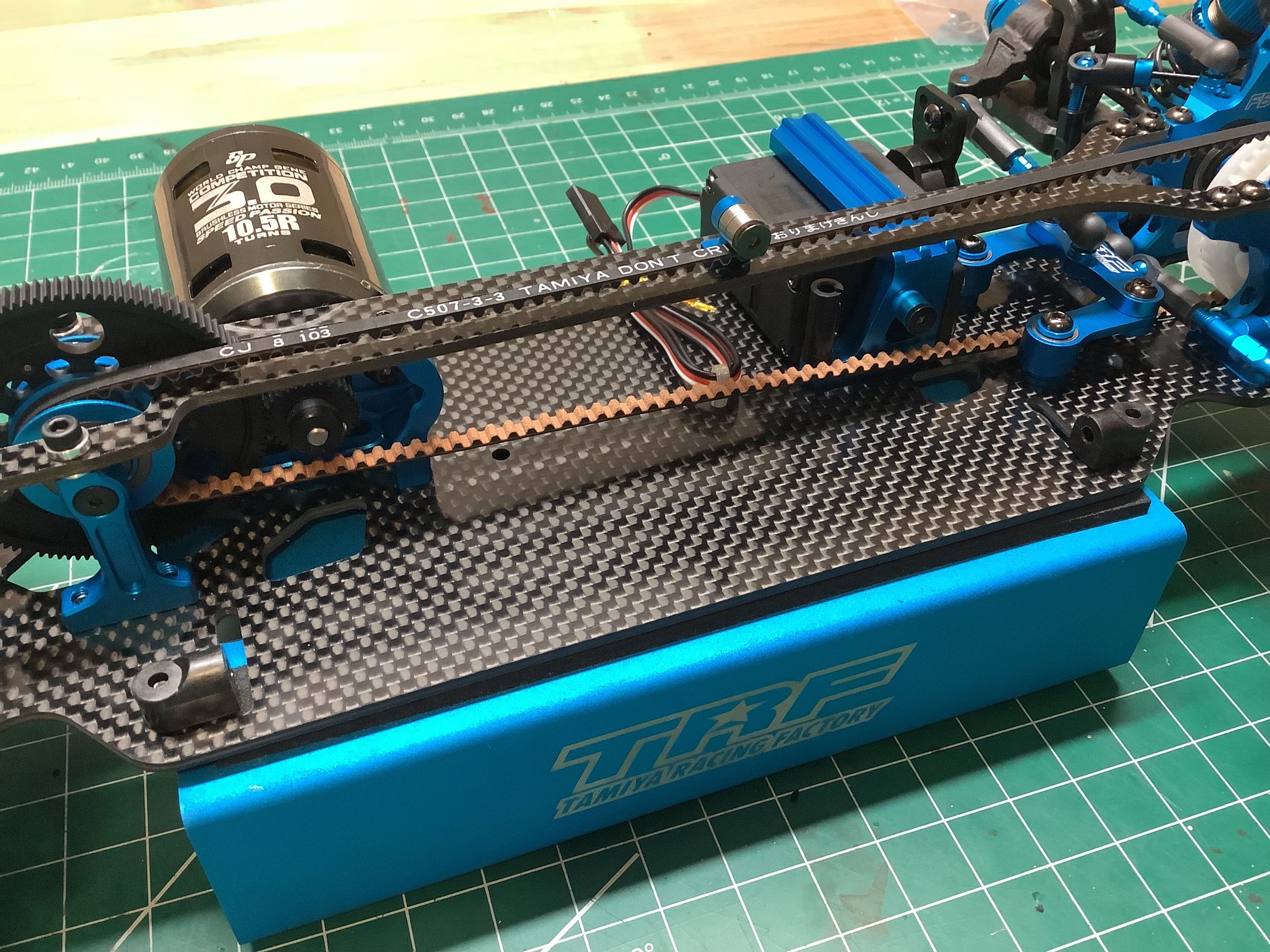
Now I've installed the battery supports which amount to nothing more
than a pair of little plastic bumpers (left). The battery is
intended to be secured with glass tape passed through slots in the
chassis to the underside. I hate this method. The TRF417X
had two slots at each end so at least the tape didn't need to go under
the chassis. This battery scheme was carried over from the TRF 417
V5. As far I can tell, there is nothing mechanical to prevent the
battery from shifting laterally into the belt except a bumper on the
side of the servo mount. Look closely to see it. The carbon
bumper support has changed slightly.
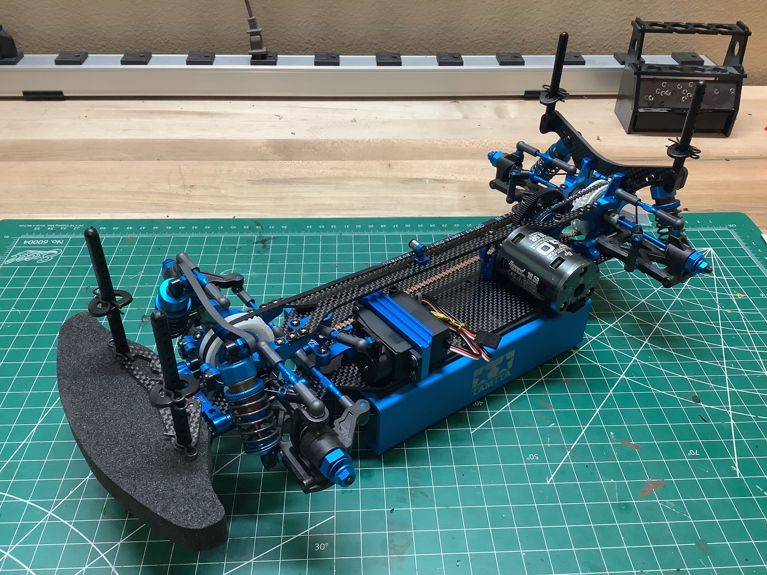
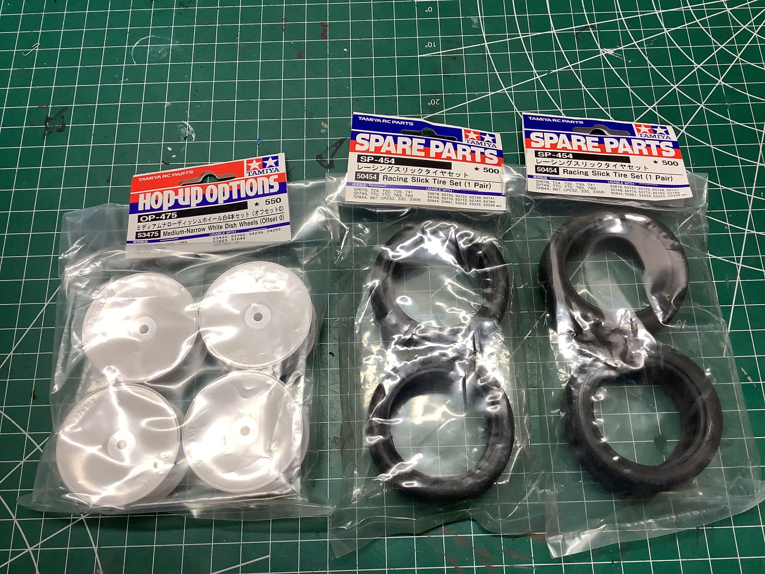
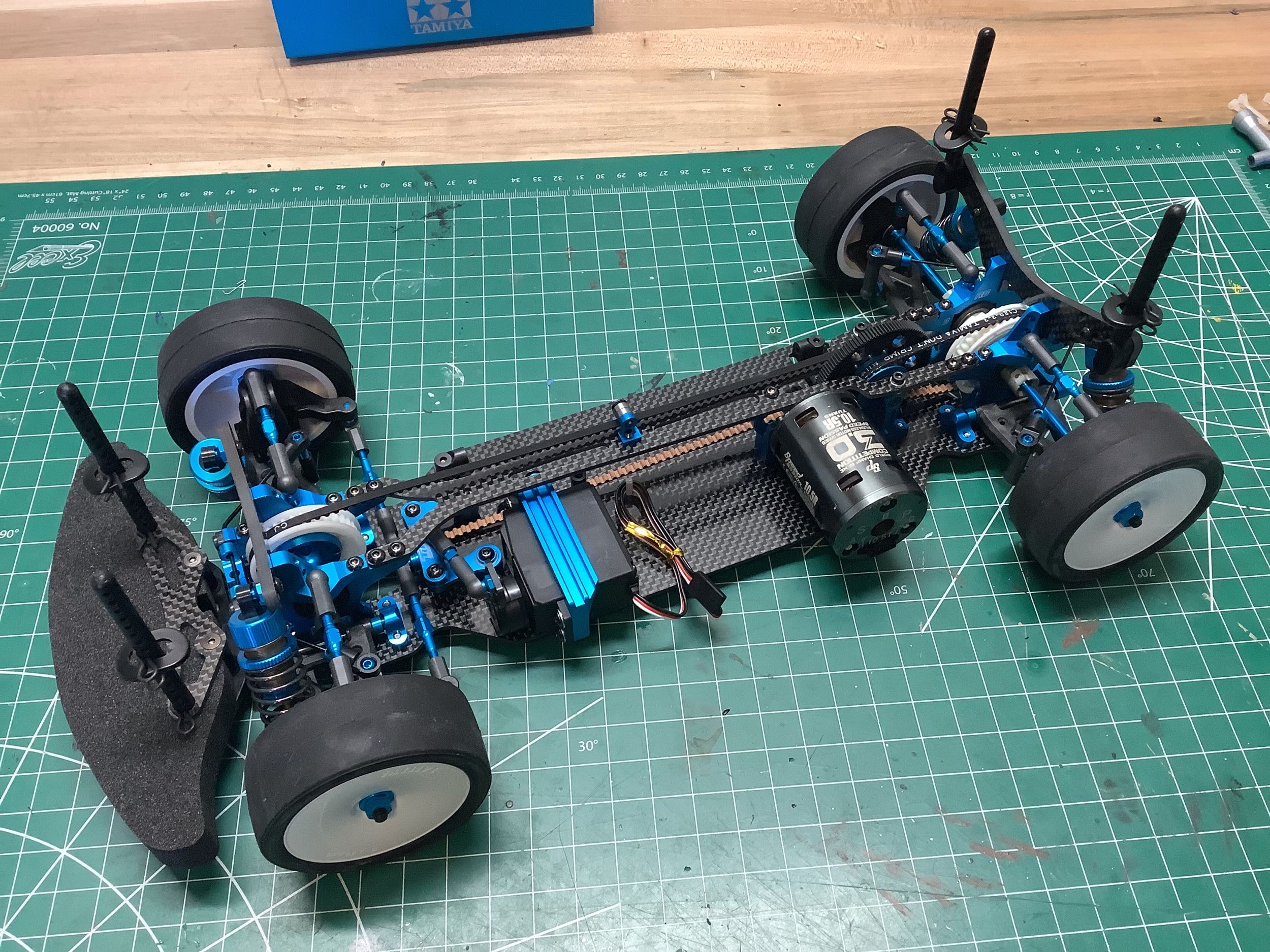
Like all the modern TRF chassis, this one came with no wheels or tires
so I used the standard dish wheels and slicks for display. That's a
good looking chassis!
©2025 Eric Albrecht