Tamiya TRF 417X Project
Page 2: Assembling the Chassis
While writing about this build, I am going to concentrate on the
differences between this and the last chassis in the TRF line I built
(the TRF 416)
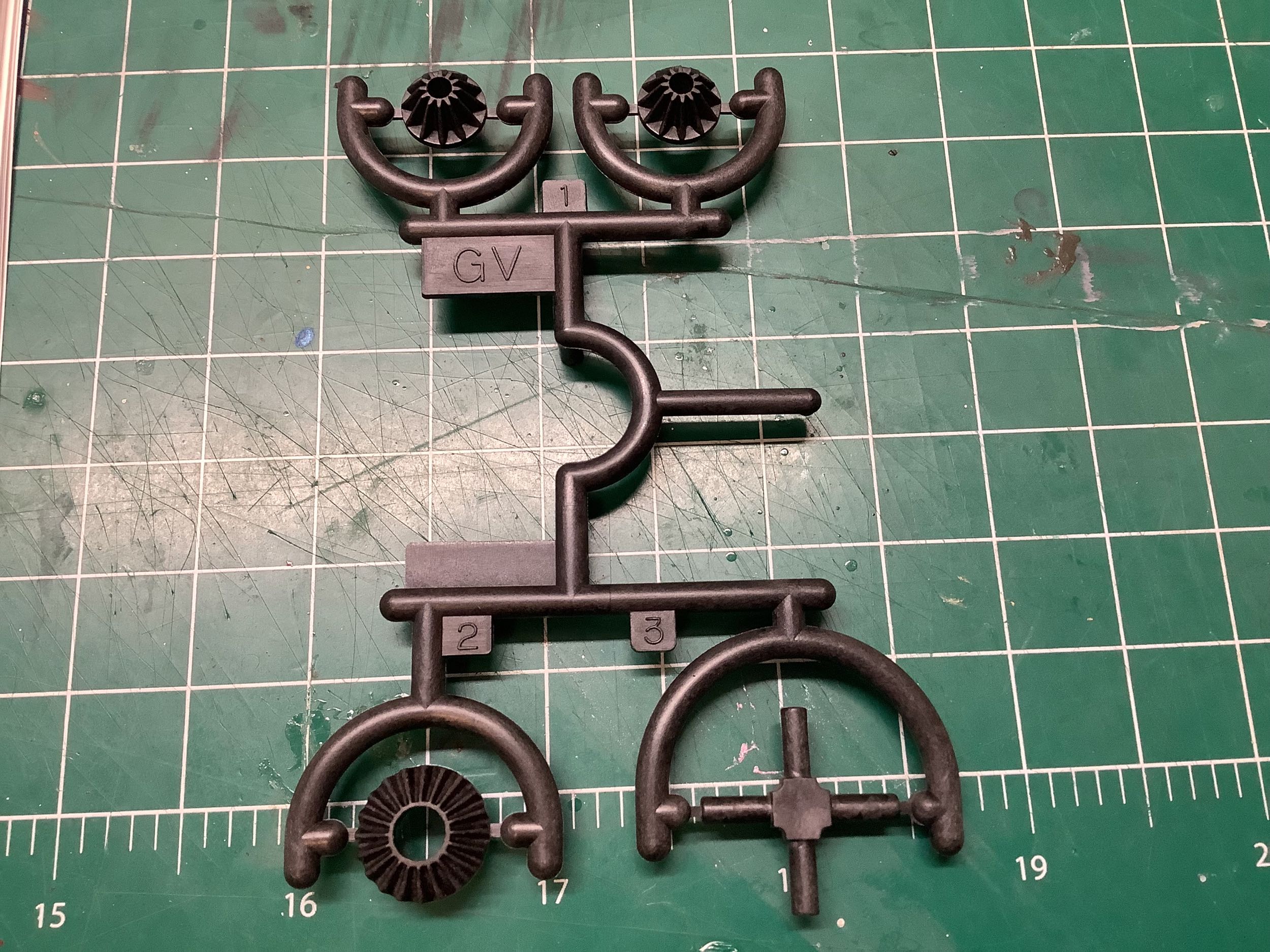
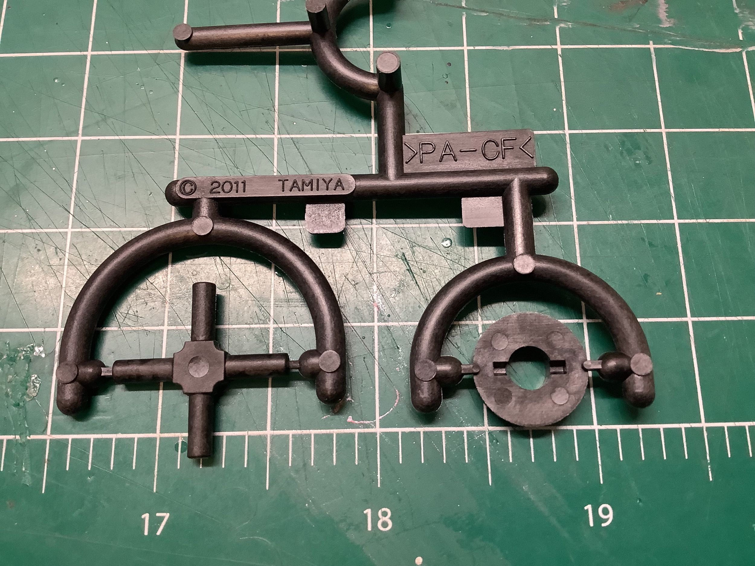
The TRF 417 (and the prior TRF models) had a ball differential but the TRF 417X came with these GV
parts which are the internal gears for a rear sealed gear
differential. The carbon filled Nylon parts were first introduced
with the TA-06 earlier in 2011, about the same time as a special edition
of the TRF 417 was released with the same option. The plastic
cross piece which supports the spider gears was not used for the TRF
models; metal shafts were used instead.
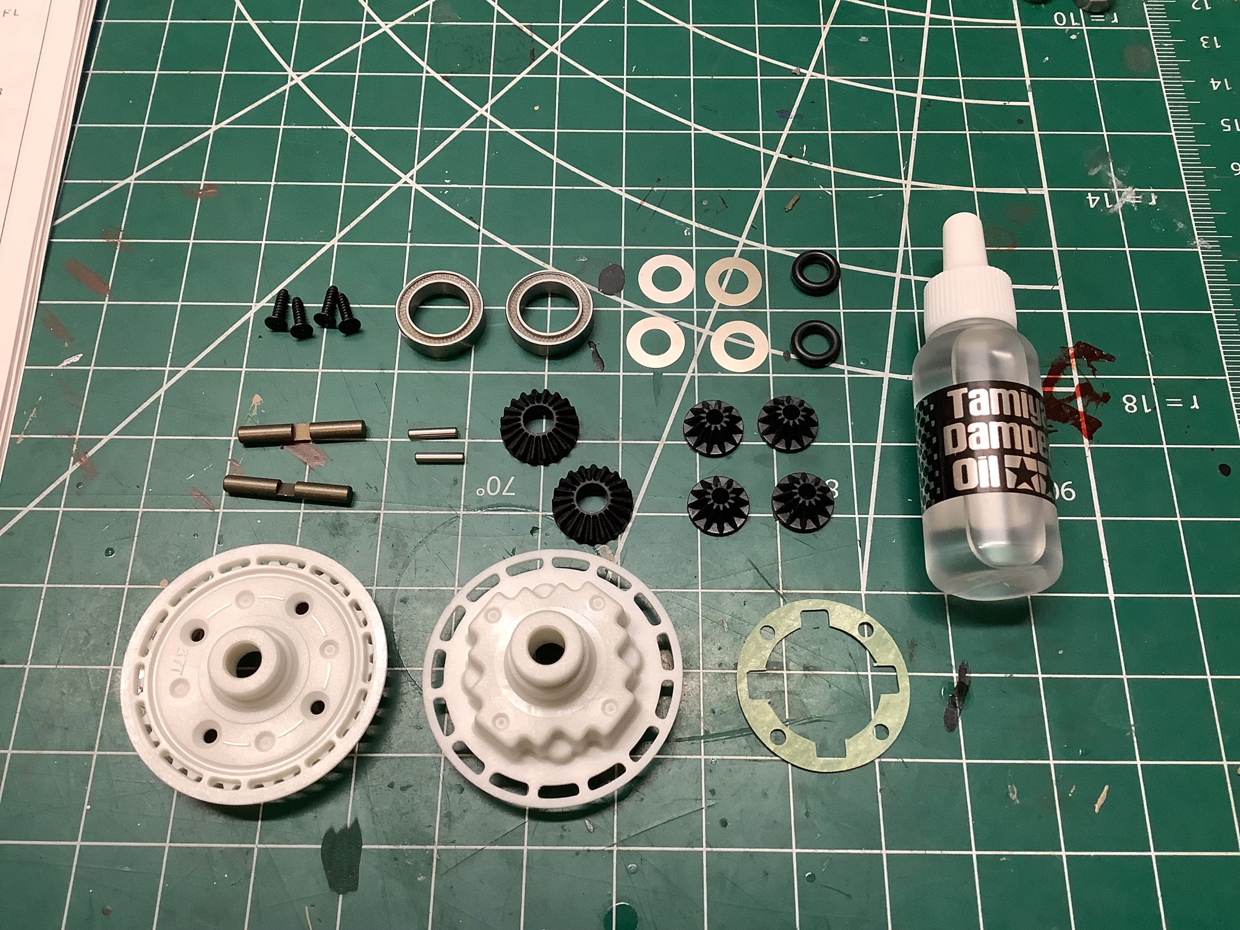
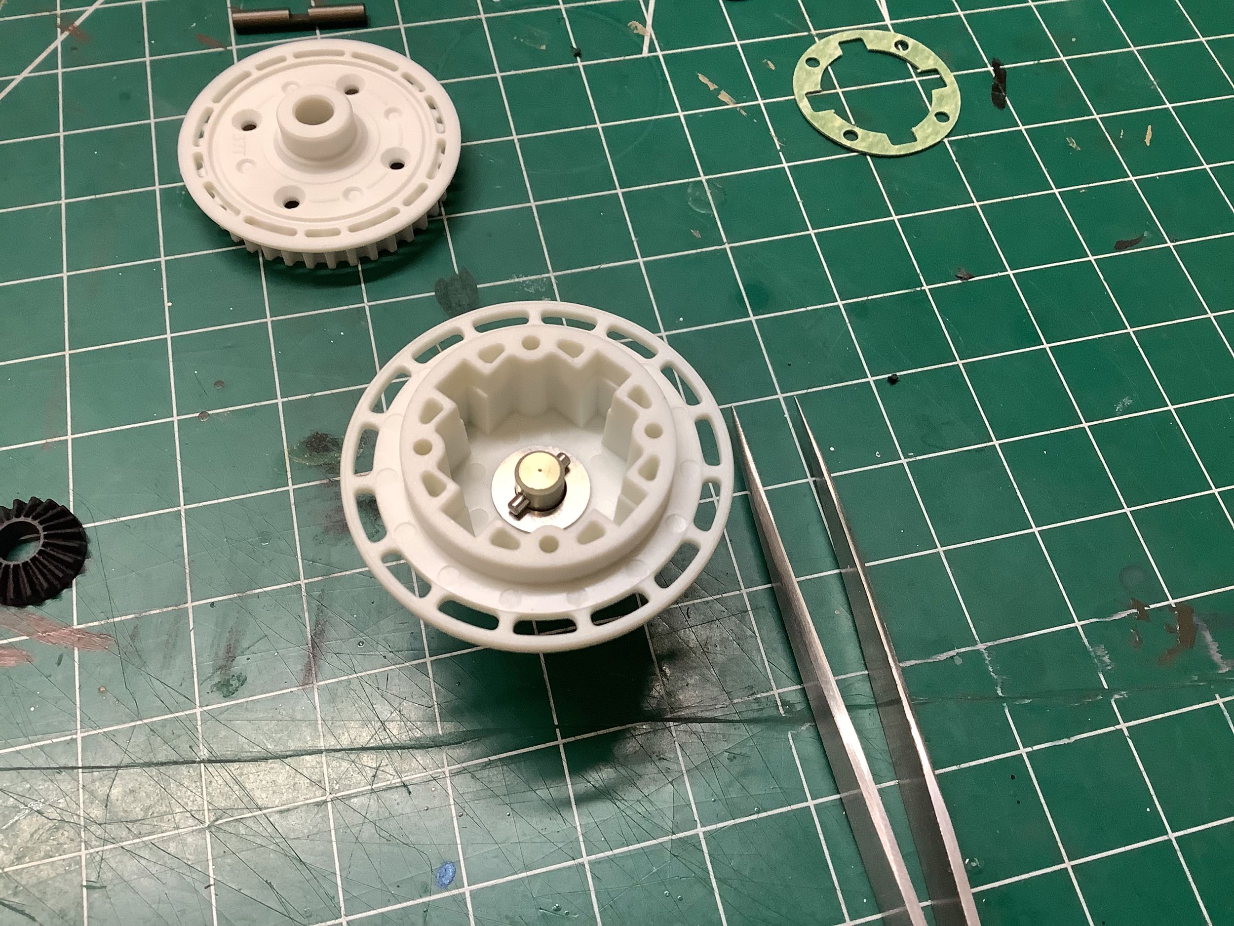
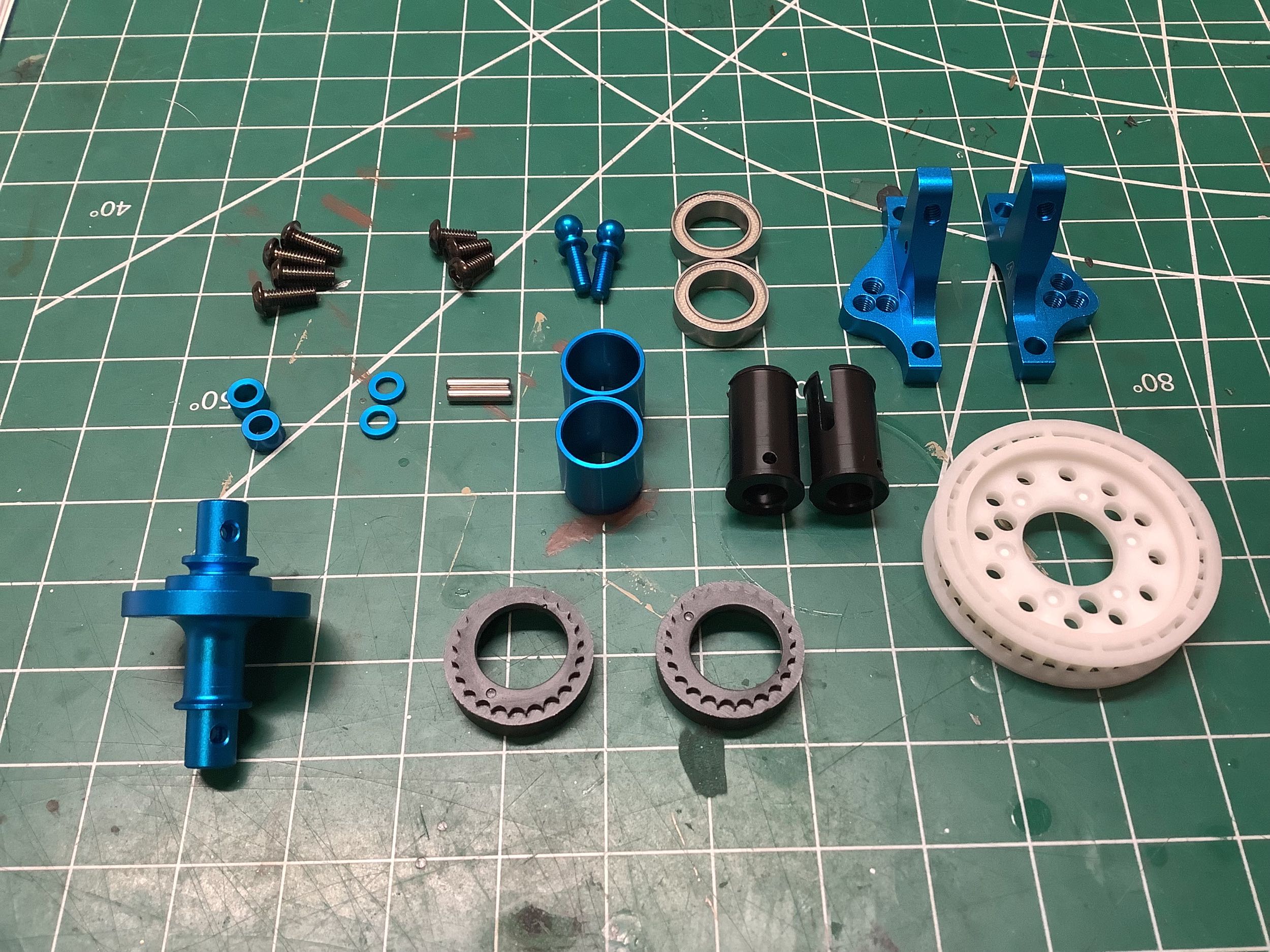
Here we can see the Delrin housing for the gear differential along
with the gears, bearings, shafts, seals, and oil. The kit comes
with clear (900 weight) shock oil for filling the differential which is
actually pretty thin and offers only minimal resistance to motion.
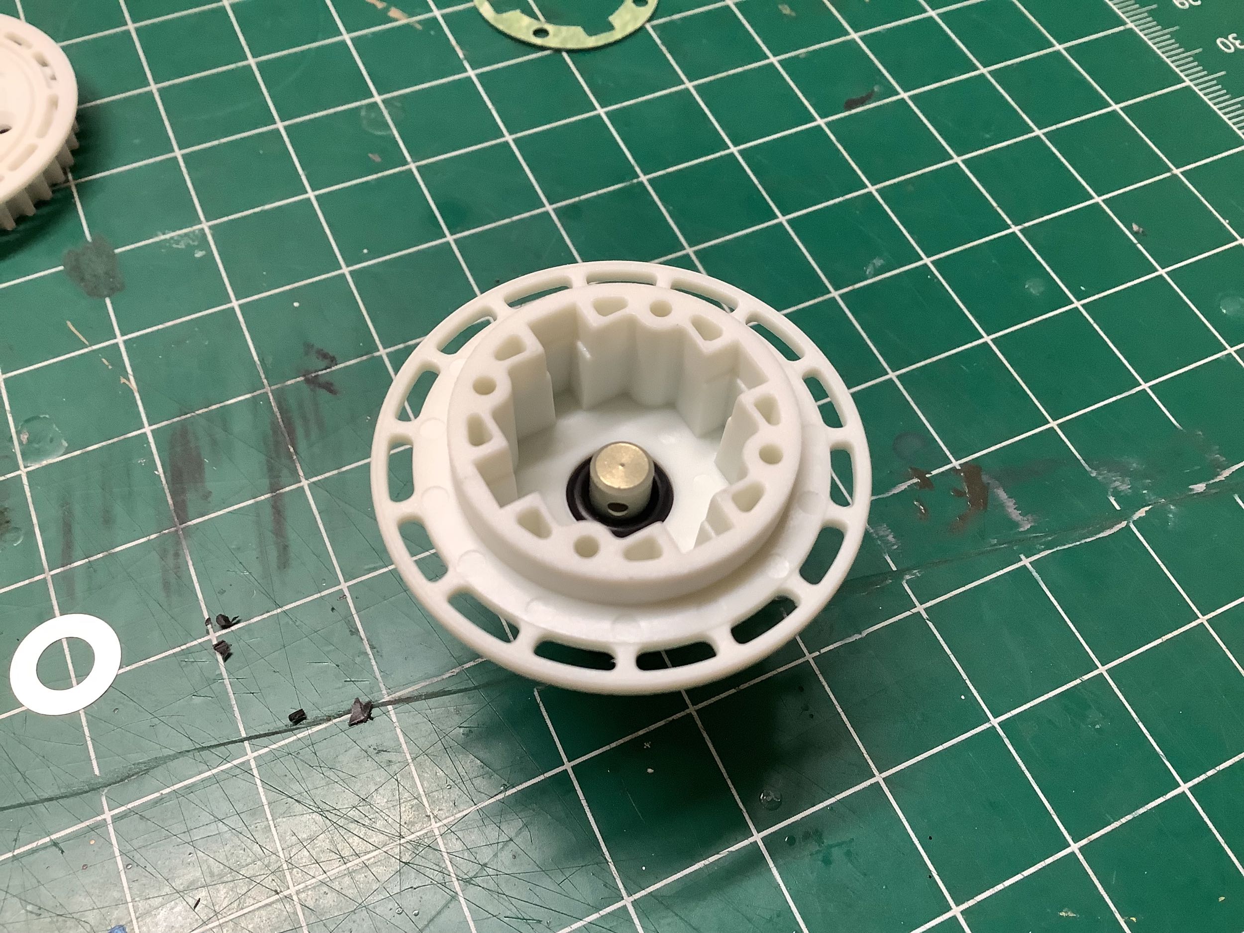
The 37T pulley is built into one side of the housing. On the
right I've inserted one of the aluminum drive cups and placed an o-ring
over it. This will serve to keep the oil inside the differential
where it belongs. There are no bearings supporting the drive cups;
they ride directly on the diff housing.
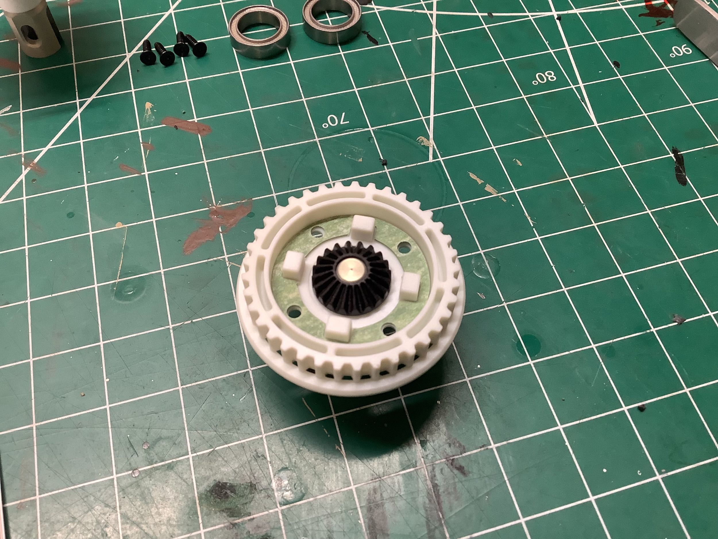
A 0.1mm shim is then placed over the seal followed by a 1.6x8mm
pin. Inserting the pin is an exercise in frustration because of
the very limited access. You'll need a sharp pointed tweezers to
manage it. The side gears fit over the pin which lock them to the
drive cups. On the right you can see that I've also installed the
gasket which should seal the two housings together.
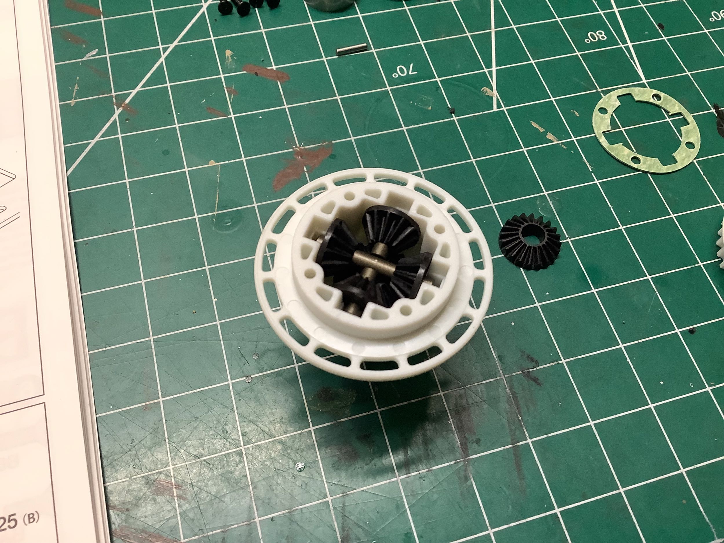
The four spider gears are supported by titanium coated cross shafts
which are notched to overlap at the center as shown on the left.
Optional steel gears are available if you want to make more noise.
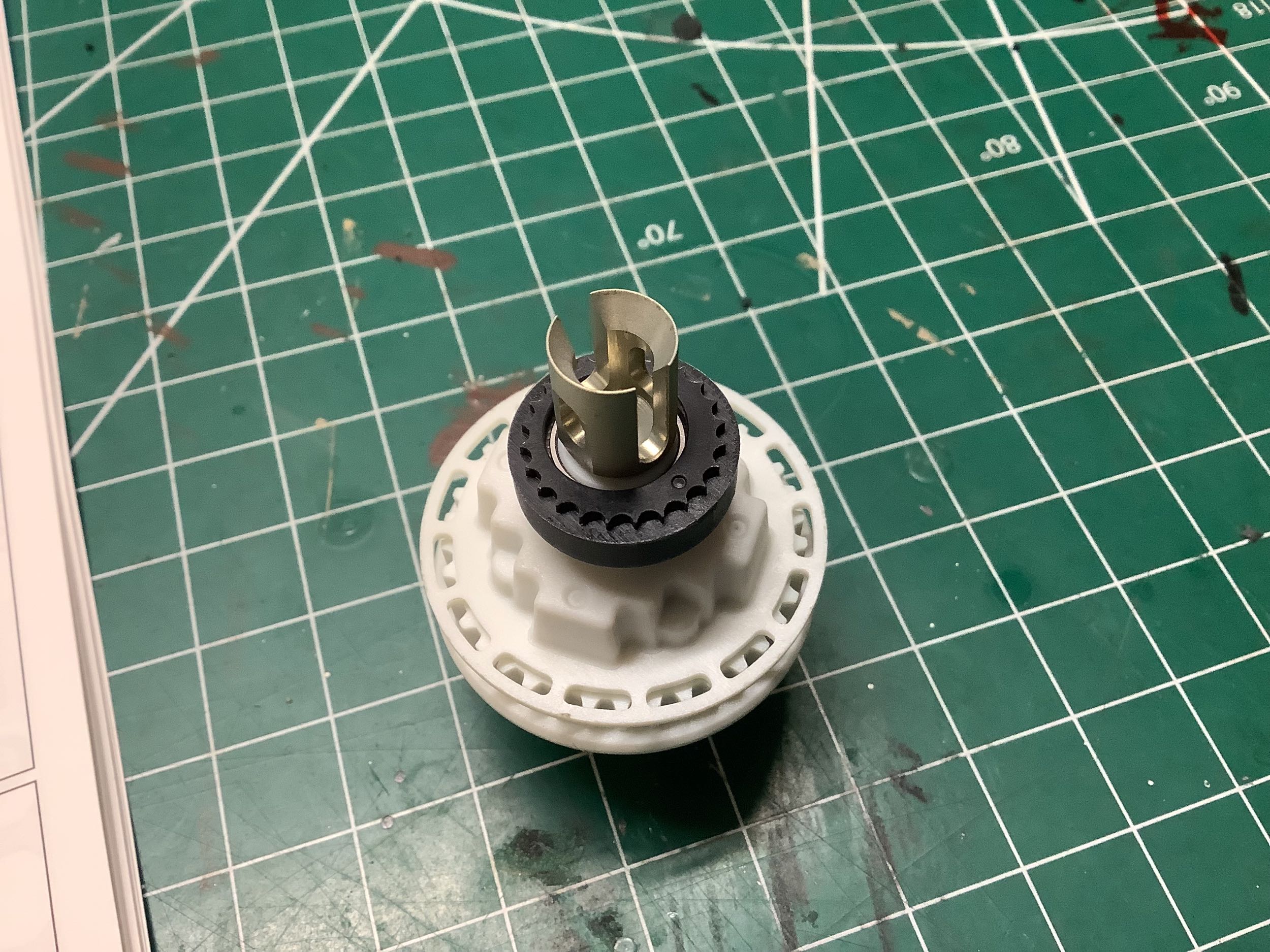
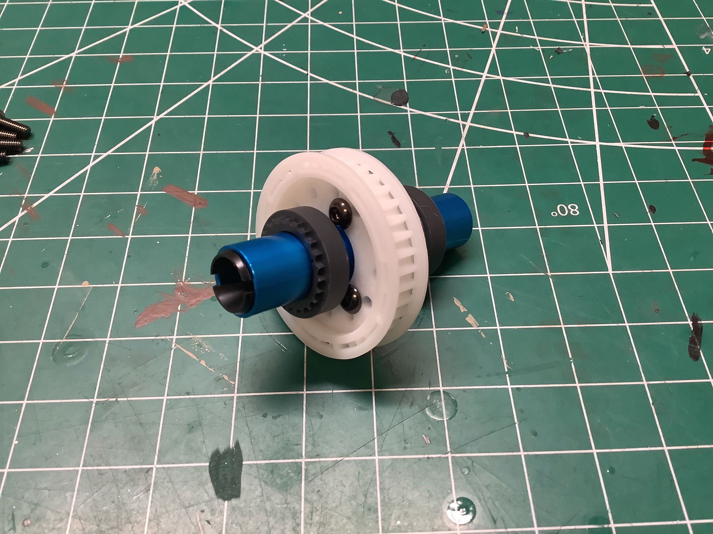
After this step the volume is filled (mostly) with oil. On the
right the two housings have been connected with four tiny 2x8mm countersunk
screws and then the large 15x10mm bearings and tensioning cams have been installed.
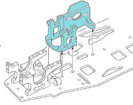
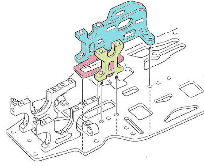
My personal suspicion is that
the primary reason for the TRF 417X was to get rid of the one-piece
center bulkhead which had to be machined out of a giant block of
aluminum and replace it with a three-piece version that could be much
more simply machined out of thin plates. Tamiya says "the previous
one-piece motor mount has been replaced with a three-piece type to
allow further adjustment of chassis flexibility by linking them
together", but that sounds like marketing spin to me. I compare
the center bulkheads in the images above, and you can see how difficult
it would be to machine the one-piece mount with only the minimal base
connecting the vertical sides. The new bulkhead could potentially
be installed omitting the center (red) part which would reduce stiffness
in the chassis, though the manual makes no specific mention of this
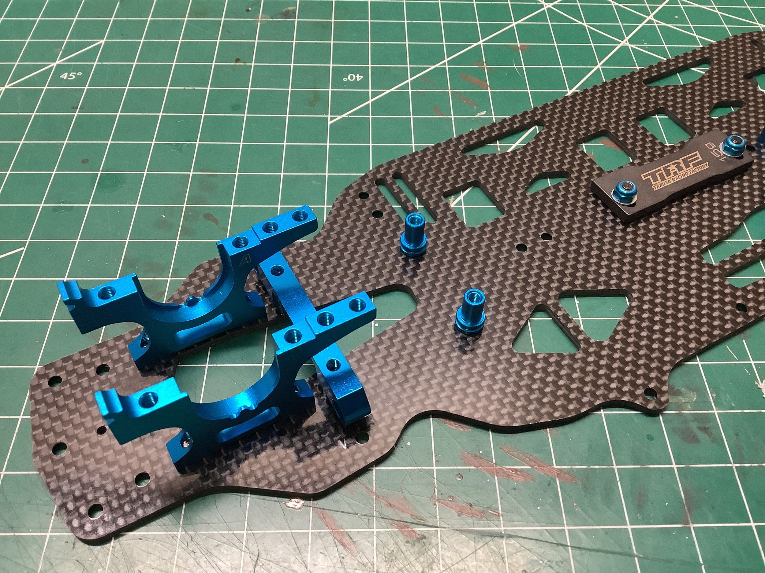
option. These images also convey the relief
cuts that were added to the lower chassis deck to add flexibility.
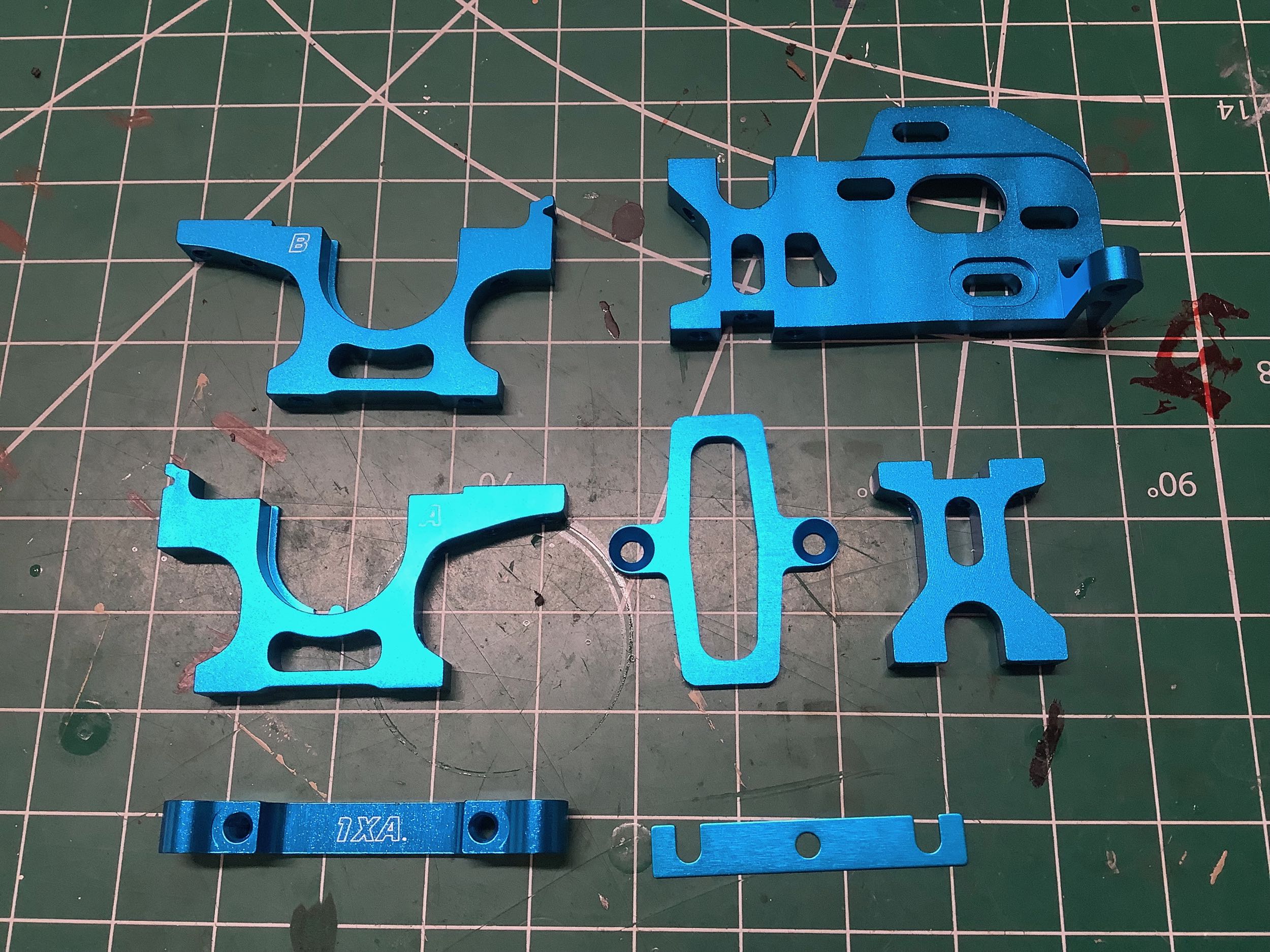
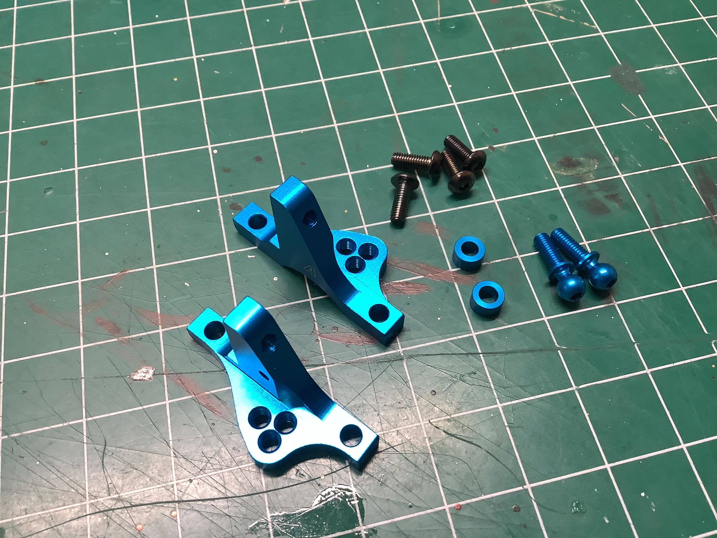
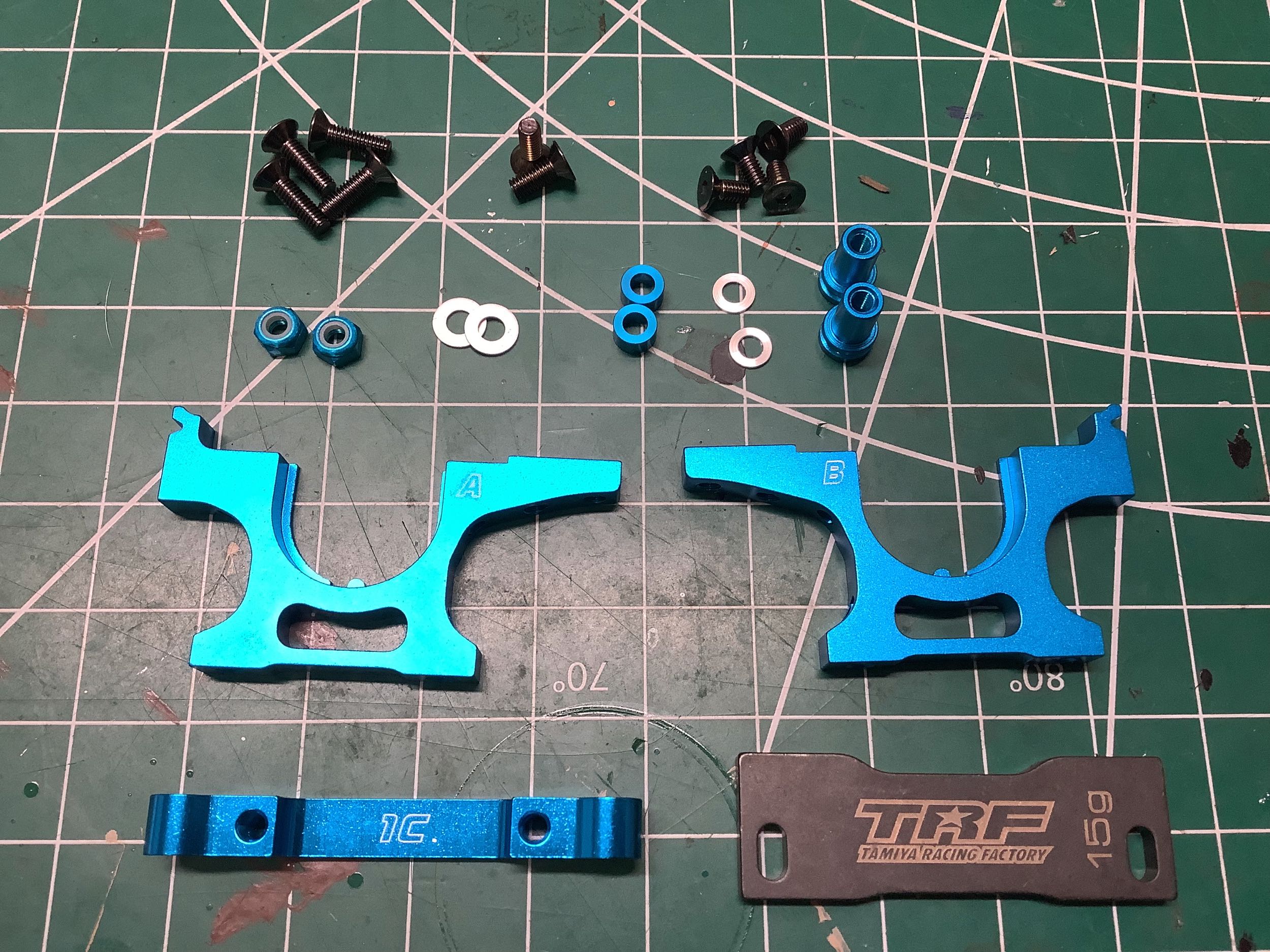
Here we can see the parts for the new three-piece center bulkhead as
well as the rear bulkheads and suspension mount. Whereas previous
models had used unique front and rear bulkheads, for the TRF 417 models front and rear use the same parts.
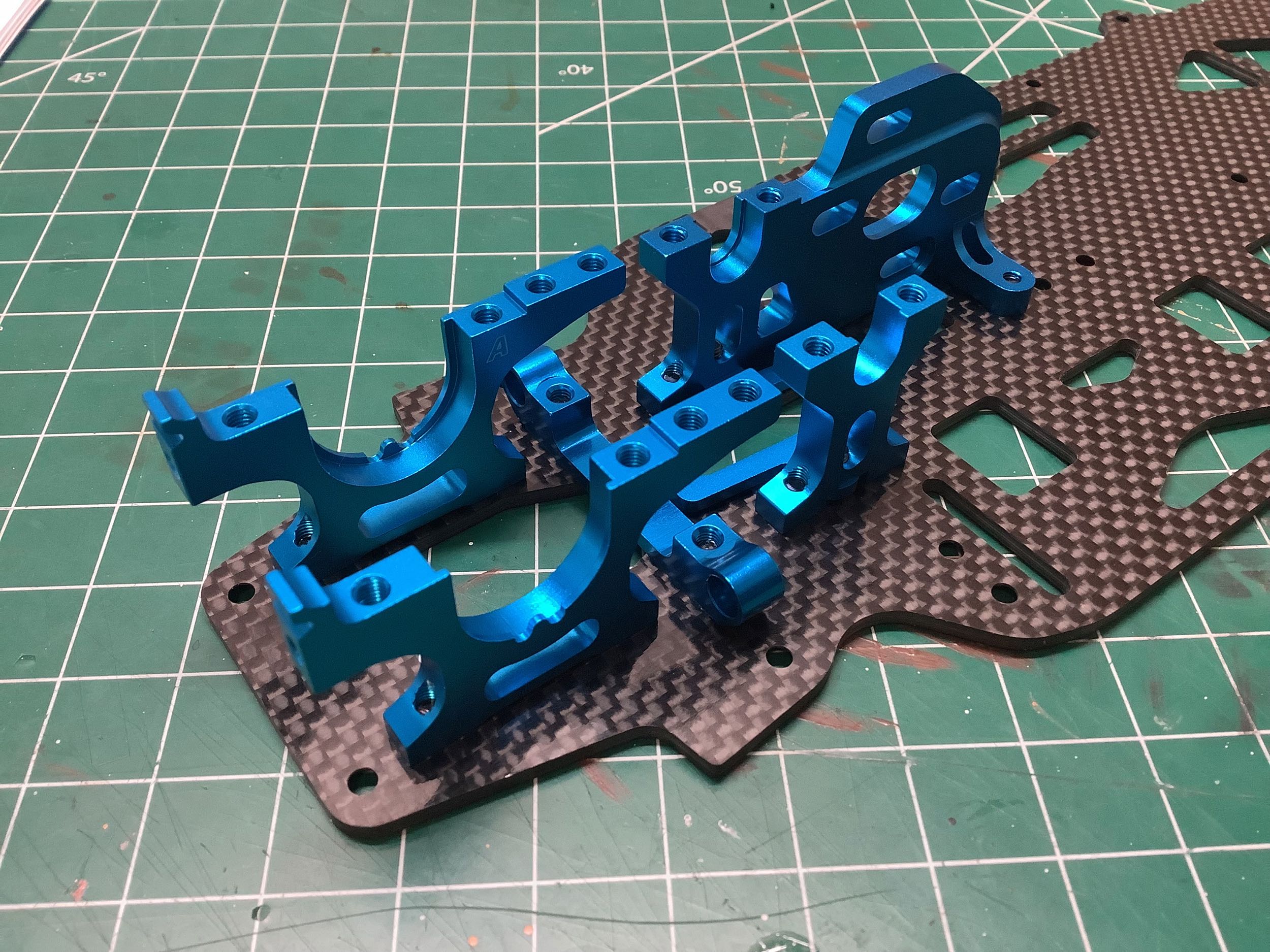
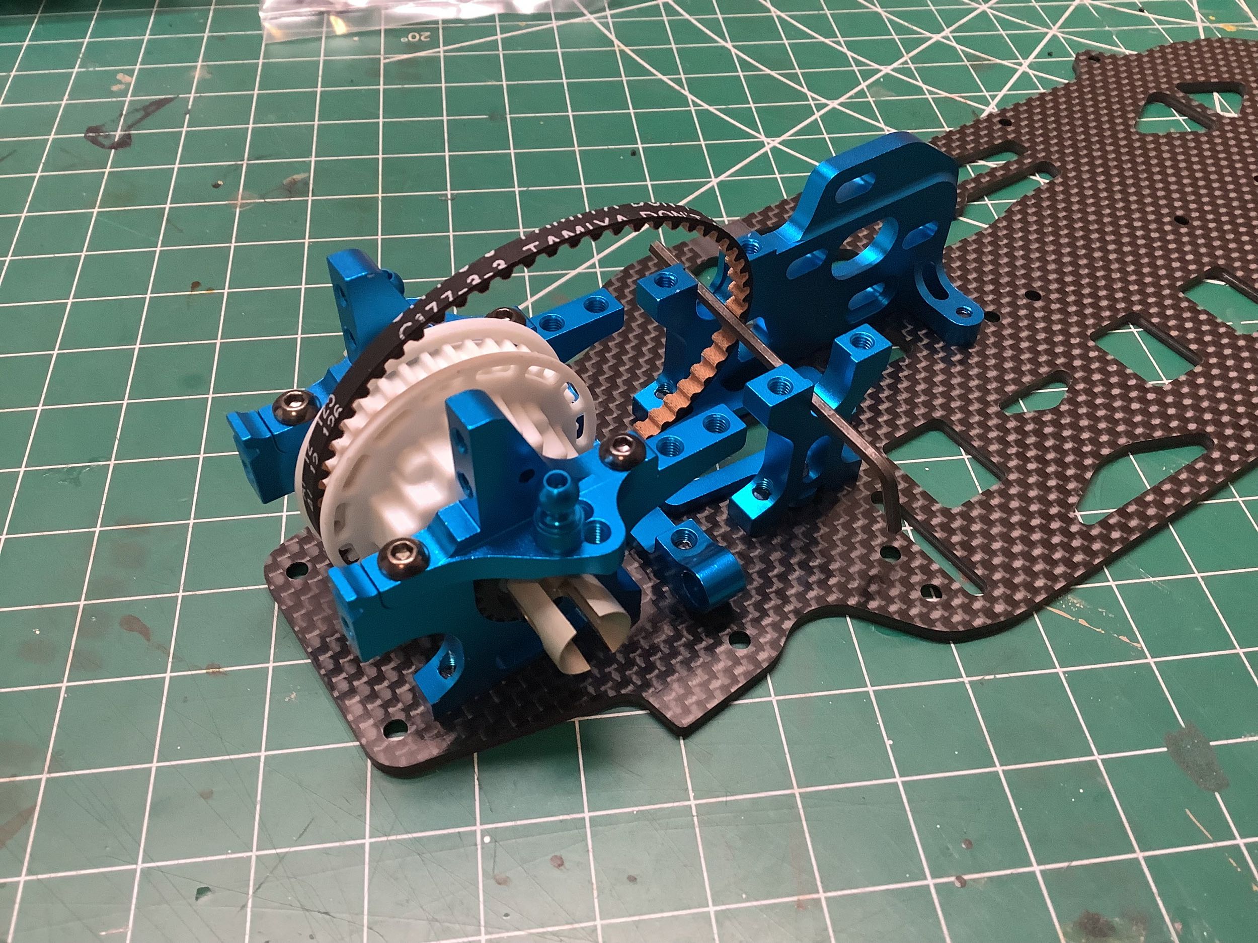
These upper bulkheads are very similar, but not identical, to those from
the TRF 416. After the rear differential is installed with the
short rear belt, the upper bulkheads capture the bearings as well as
providing three mounting hole options for the upper suspension links.
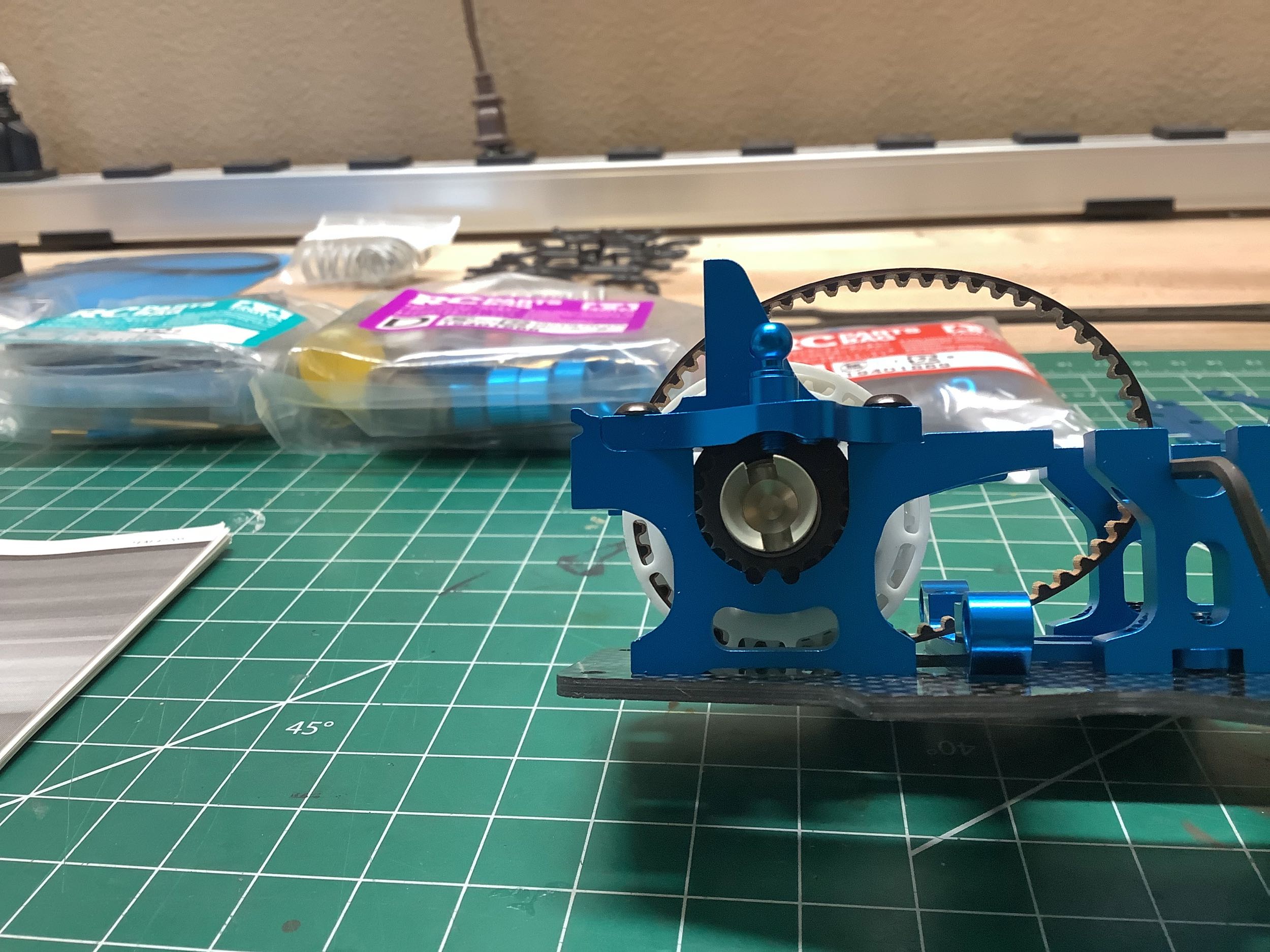
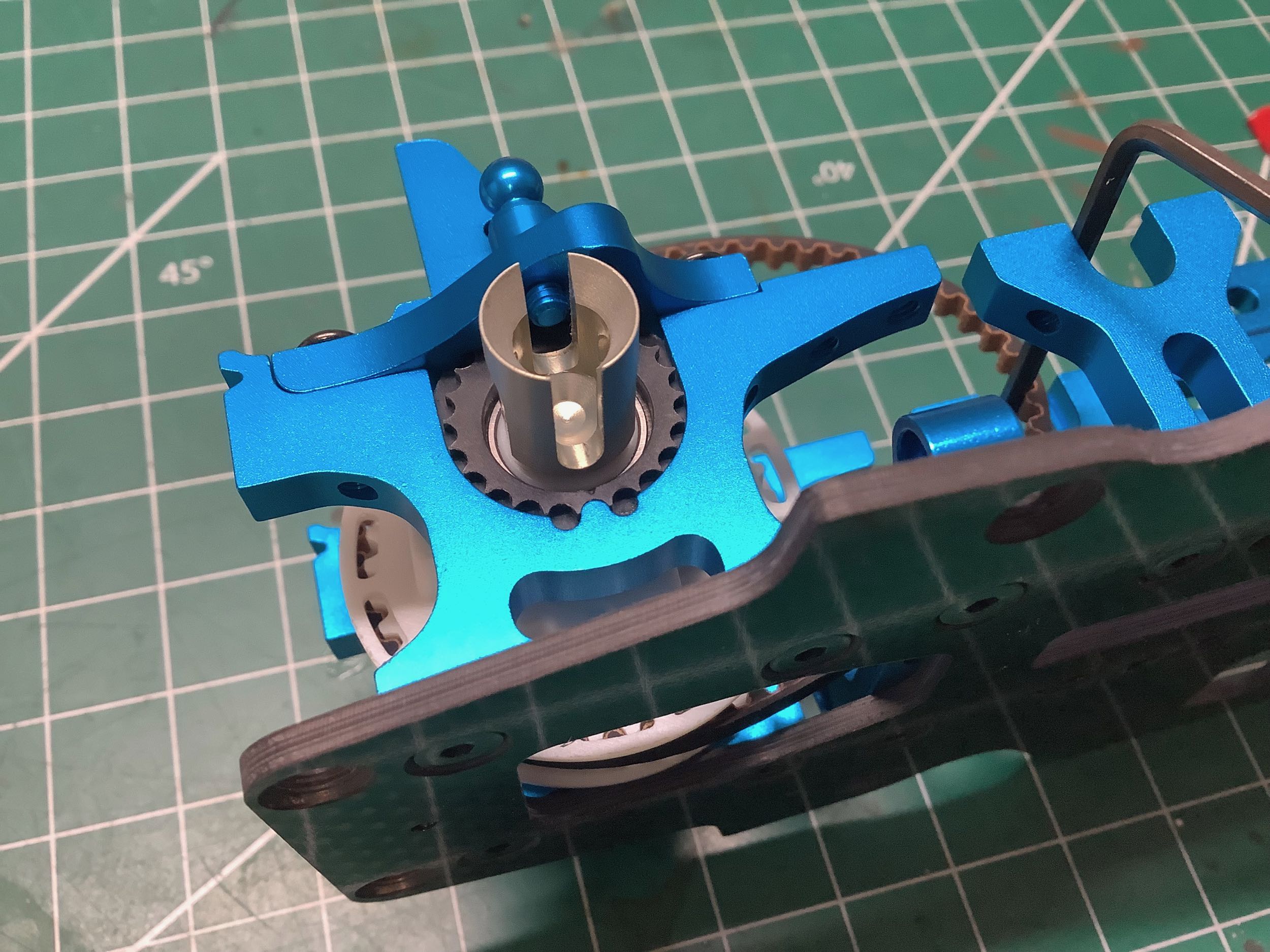
These pictures show the belt tensioning cams. The picture on the
right shows the little triangular indexing mark which is aligned with
the tang on the bulkhead for the default position. The cam can be
rotated to move the bearings forward or backward to add or relieve
tension on the belt. The whole cam can also be flipped 180 degrees
(aligning with a circular mark instead of the triangular mark) to
decrease the ride height.
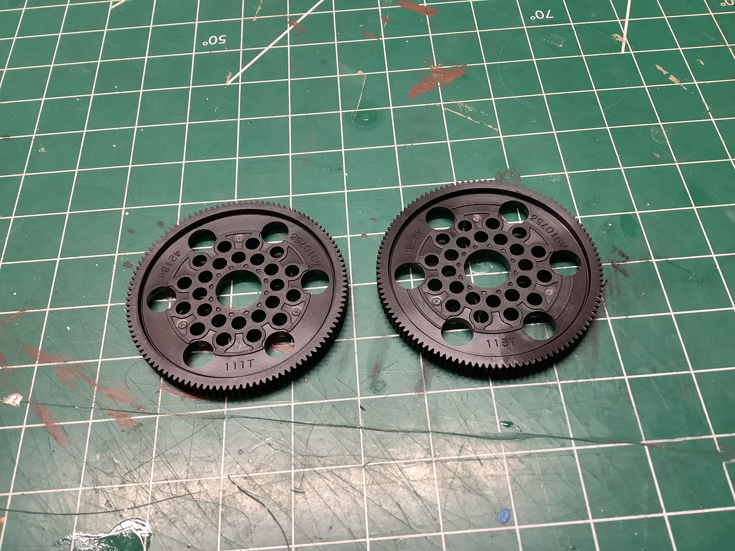
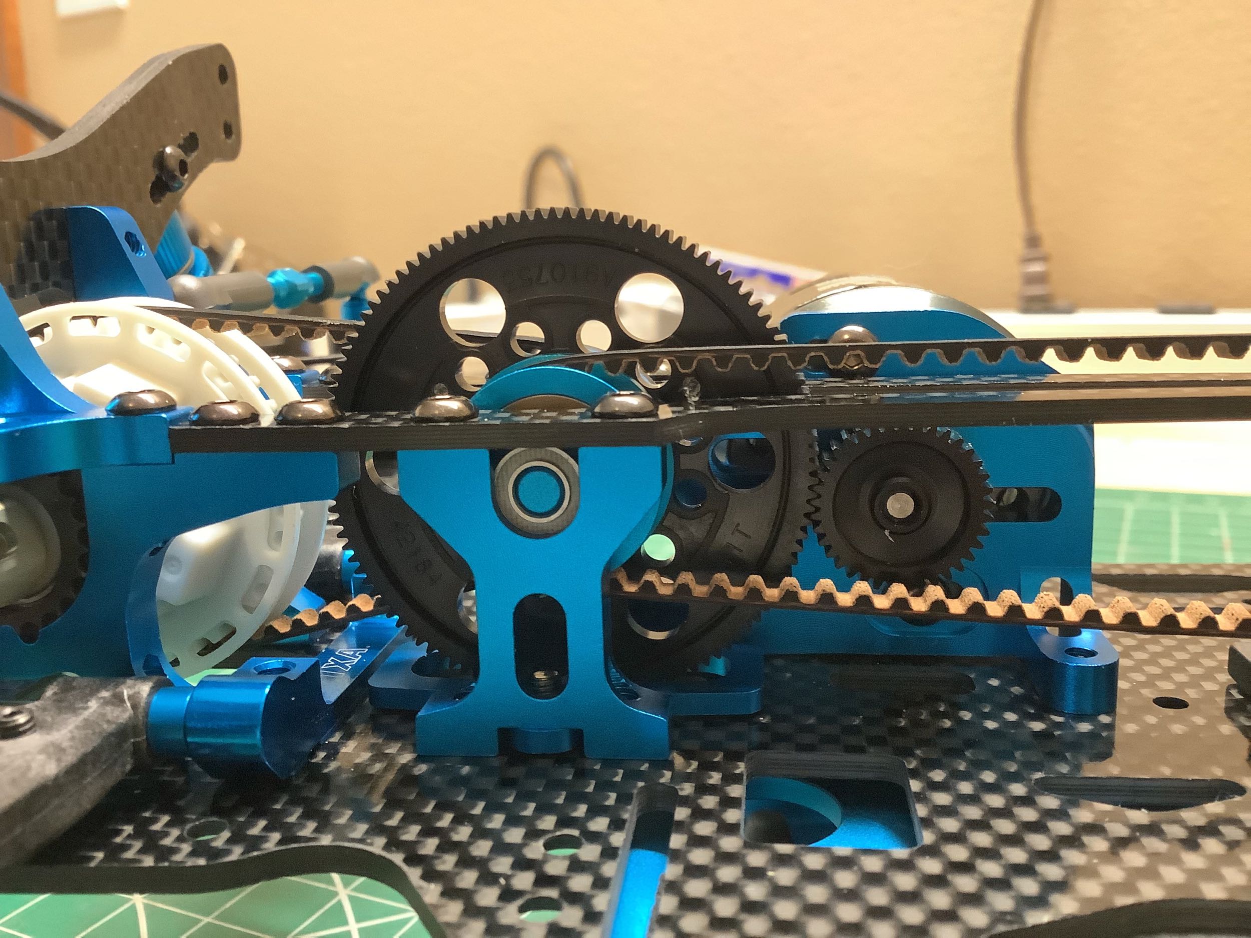
The 105T spur gear from the TRF 416 has been replaced with two options:
111T and 113T (left). Those six large holes around the outer edge
are used to access the motor mounting screw. The 15T center
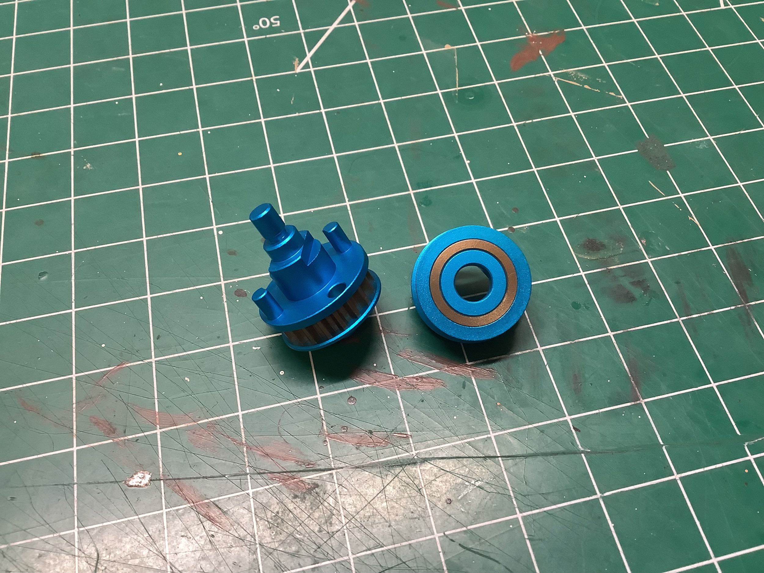
pulleys have also been replaced with larger 19T versions (right).
These seem to be made from three parts: an aluminum housing and cap, and
a bronze toothed pulley. It is not immediately clear how these
are connected, but I suspect they are just pressed together. They
cannot be disassembled.
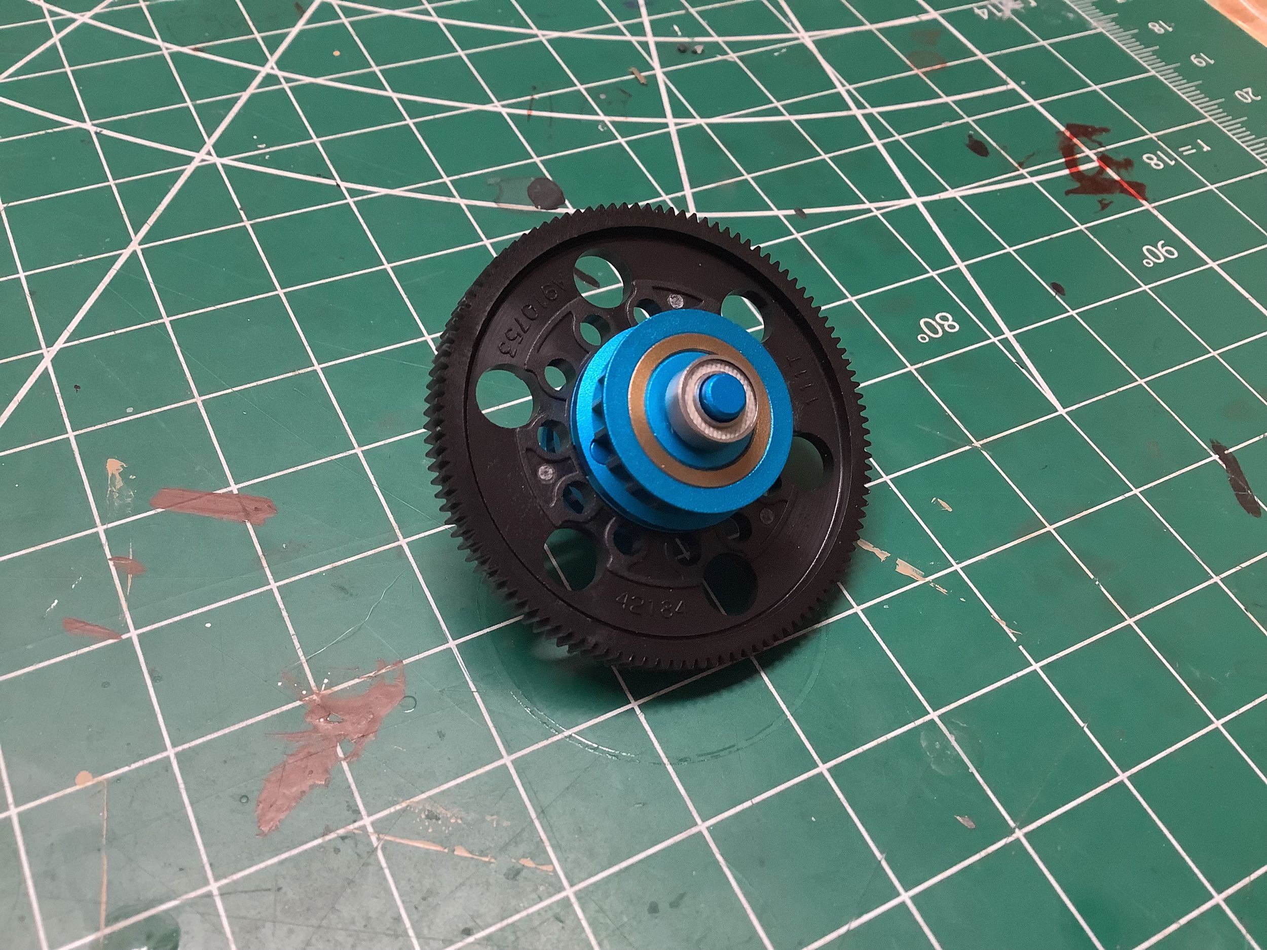
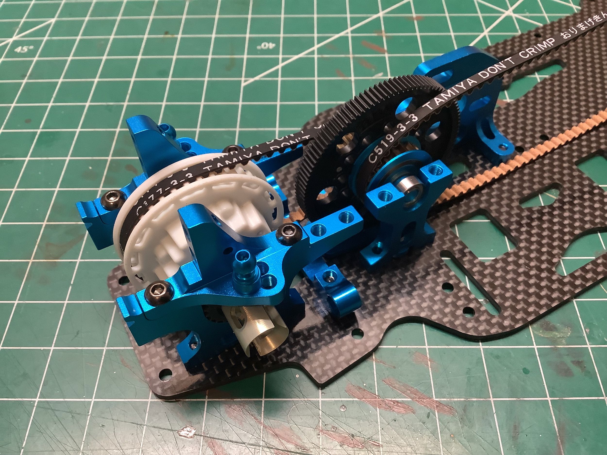
The pulleys are connected directly to the spur gear so there is no
center one-way bearing in this design. The center shaft assembly then
drops into the center bulkhead. One subtle difference from the TRF
416 is that now the short rear belt is on the left side of the spur
gear instead of on the right. This leaves slightly less room for
the battery but more room for electronics. This may have been done
because the TRF 417 was the first Tamiya chassis designed for brushless
motors which use larger controllers, and lithium batteries which are
much lighter and can be installed further outboard.
Now we can install the front bulkheads, front suspension mount, and
steering posts. That black steel part with "TRF" written on it
doubles as both a 15g ballast weight and a side positioning stop for the
battery.
All of the TRF chassis had used a front one-way through the TRF 416
until the World Edition. The TRF 417 models all use a front direct
coupling which is just a solid shaft that passes through (and locks to)
the front
pulley and attaches directly to the drive cups. These are plastic
drive cups with an aluminum retaining ring over them, presumably to keep
them from ballooning at high rpm. I'm not sure this strategy
saves anything over just making them from aluminum to start with. I
suppose the plastic provides some amount of cushioning when applying
sudden power to the front axles.
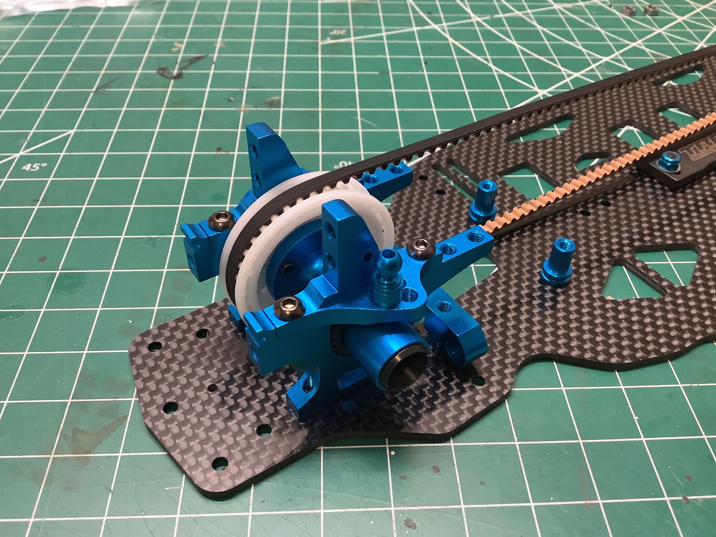
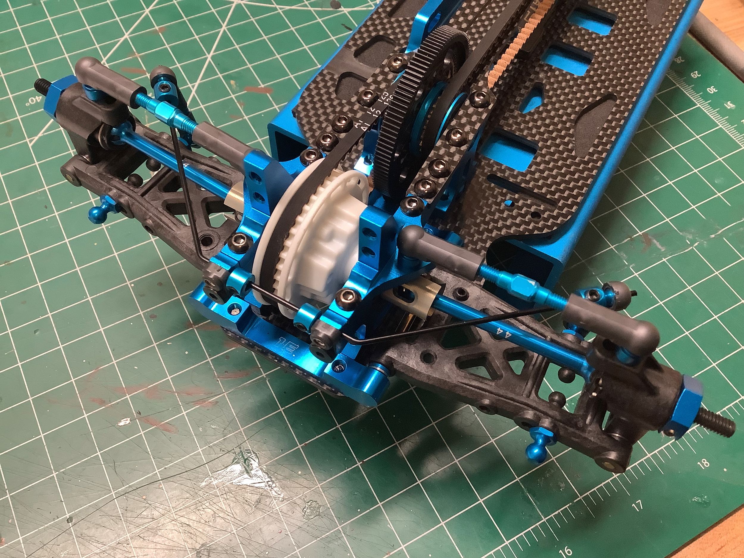
Here the front pulley has been installed and captured by the upper
bulkheads. The front upper bulkheads are the same parts used on
the rear. Both belts are now installed and tensioned.
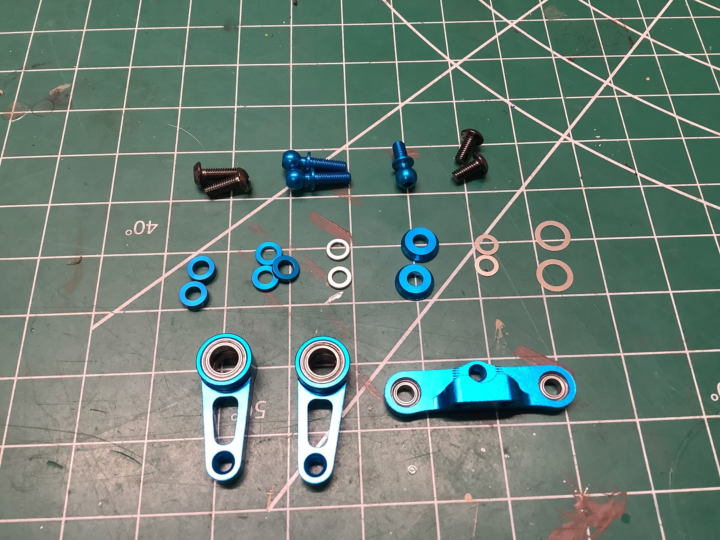
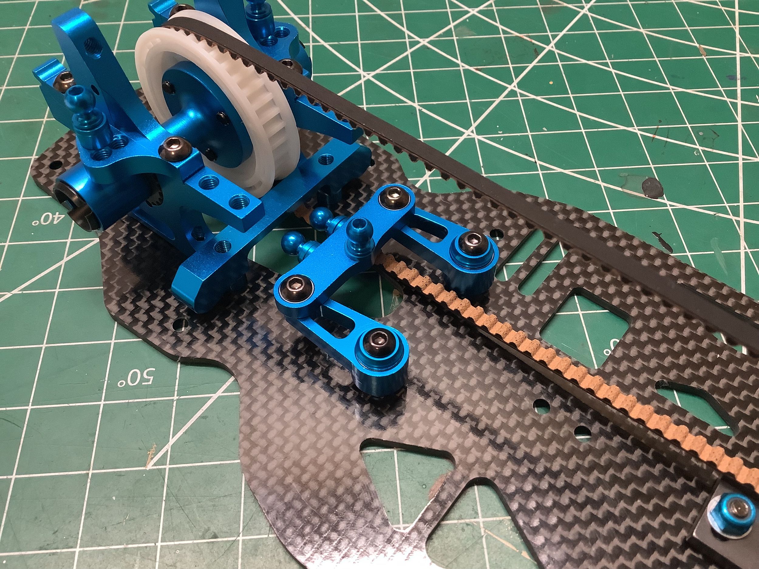
These steering cranks and bridge are very similar to those from the TRF
416. One difference is that there is now no bracket
connecting them together and to the upper chassis deck; instead they just float above the lower chassis deck. This
supposedly adds more flexibility to the chassis.
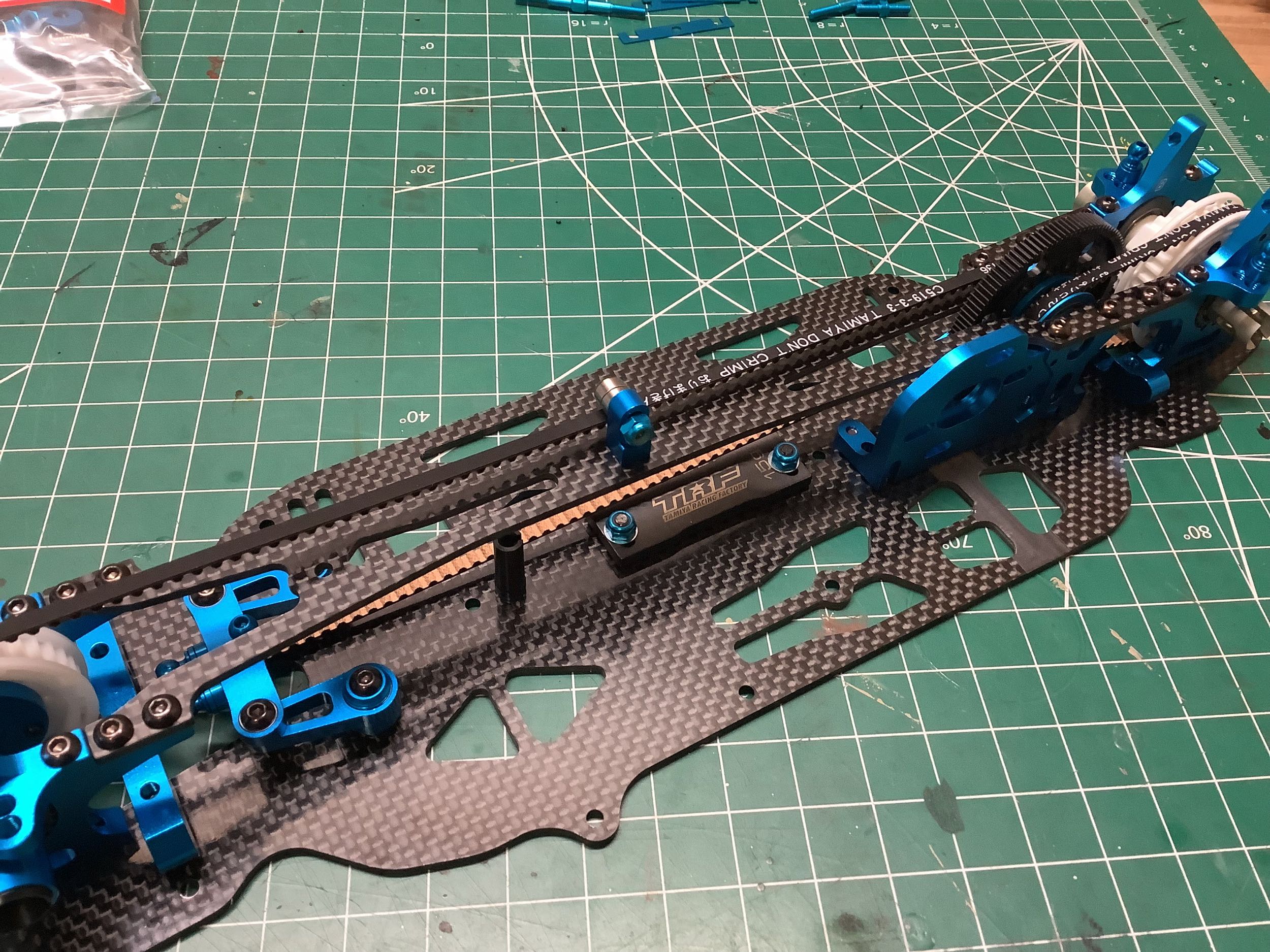
The upper deck connects the front and rear bulkheads and also captures
the bearings for the center shaft. This means the whole upper deck
has to be removed to access the center shaft for maintenance.
There is also a smaller upper brace that connects the rear bulkheads to
the center bulkheads. There is a center belt support
built into the upper deck as shown on the right.
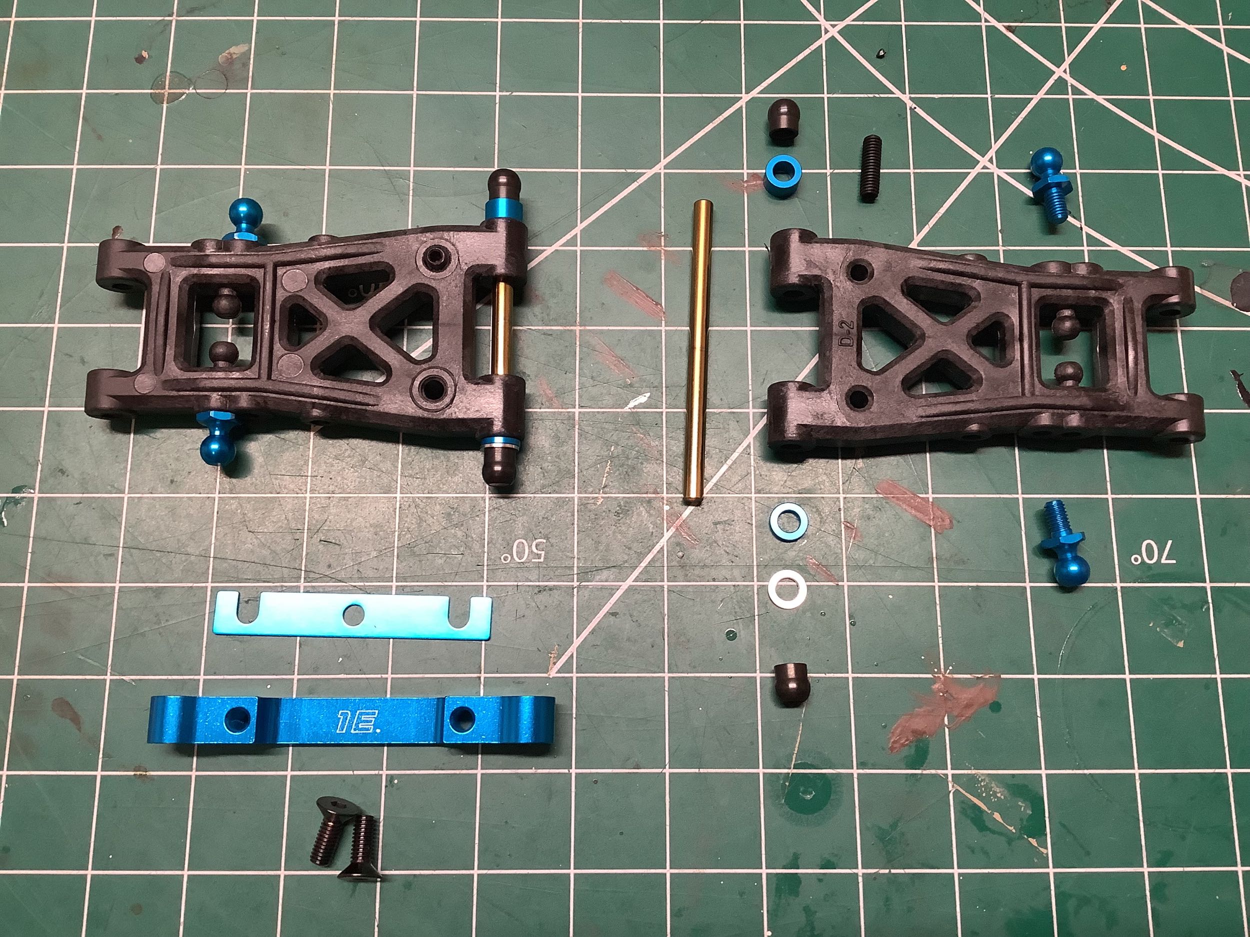
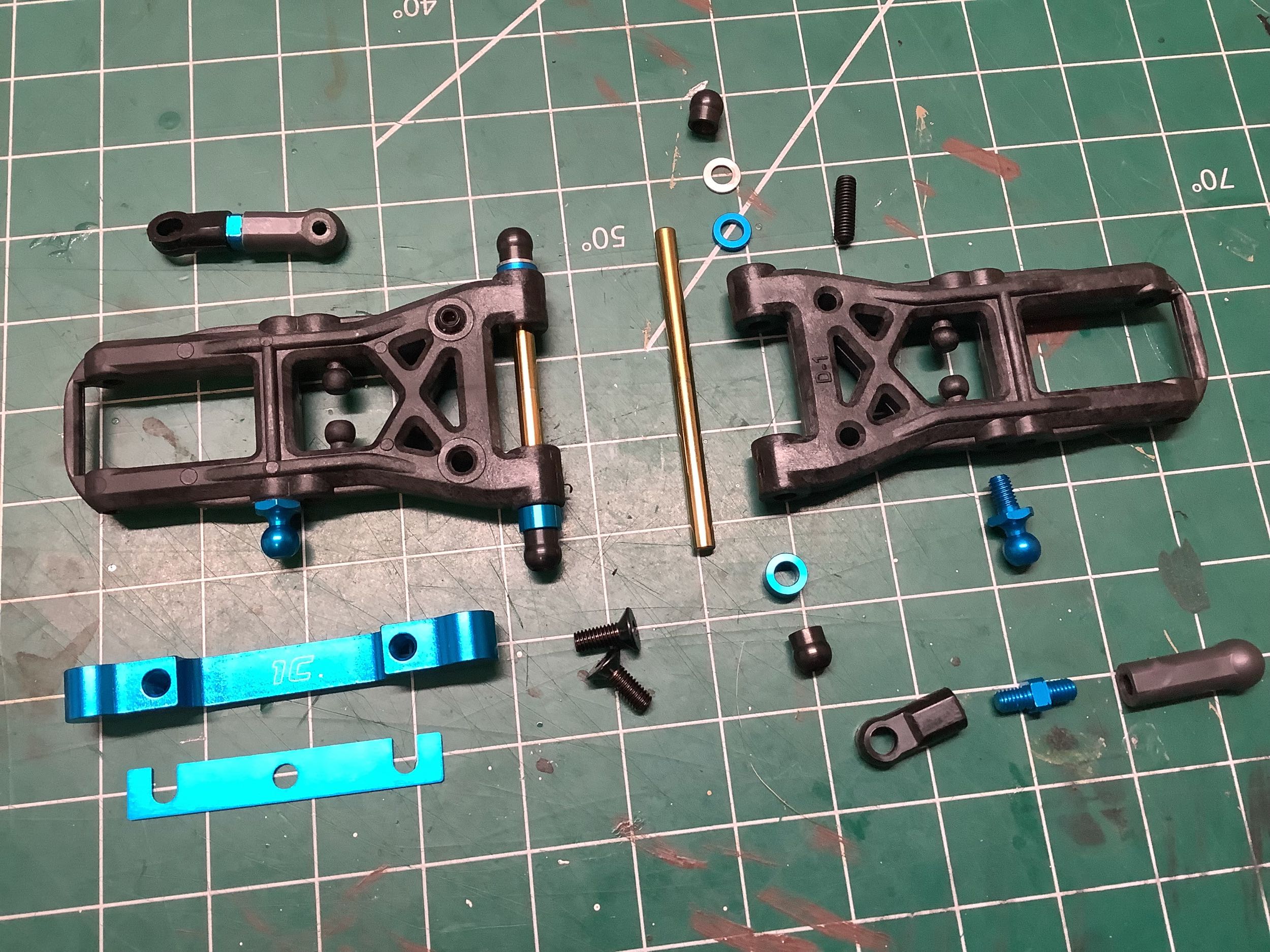
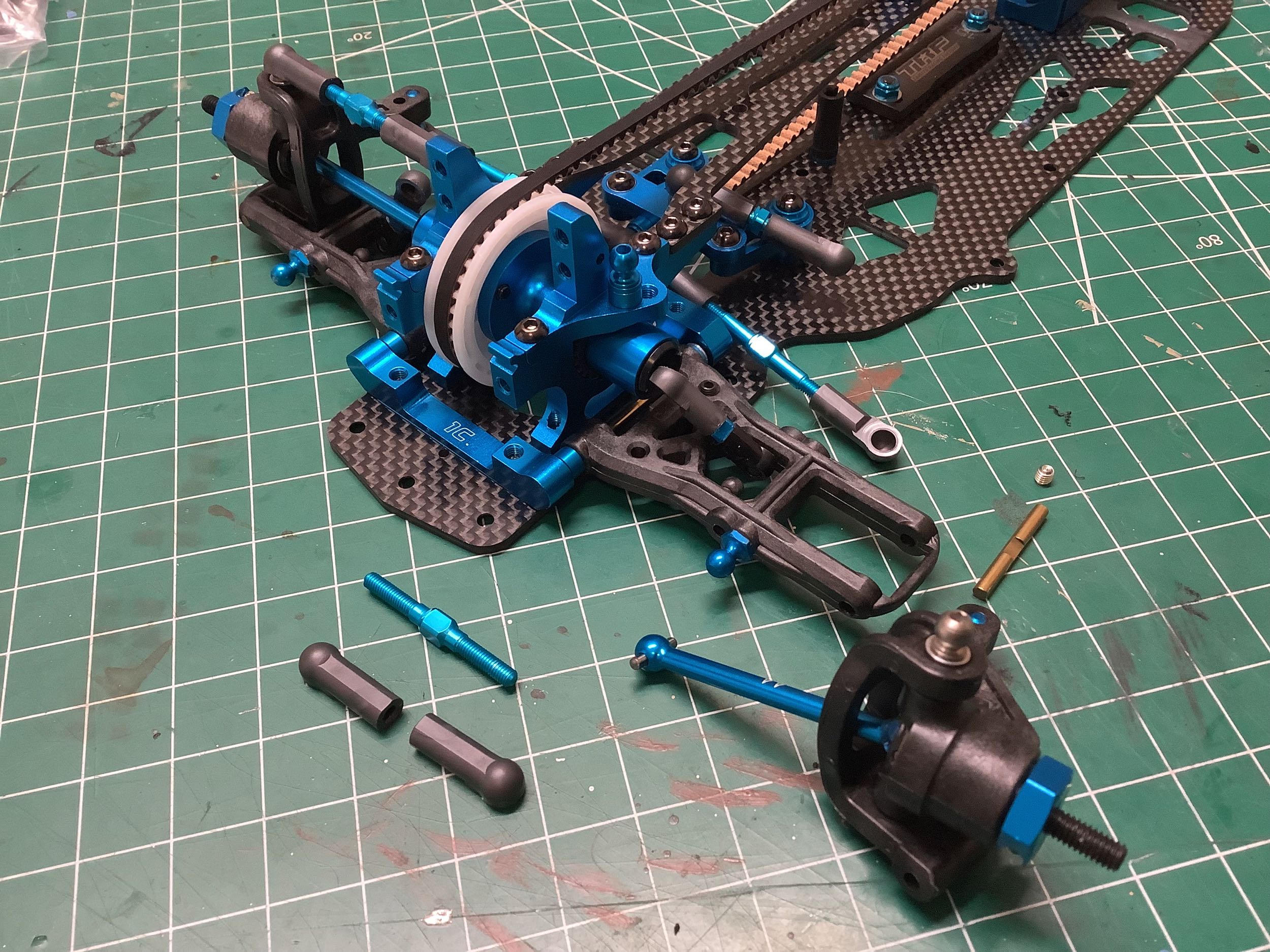
Tamiya sure does like changing suspension arms. These new arms
(front and read) were introduced with the TB Evolution 5 and have more symmetric bracing
compared to the older arms. They are made from carbon filled
plastic and are quite rigid. Flipping them allows access to different ball joint positions.
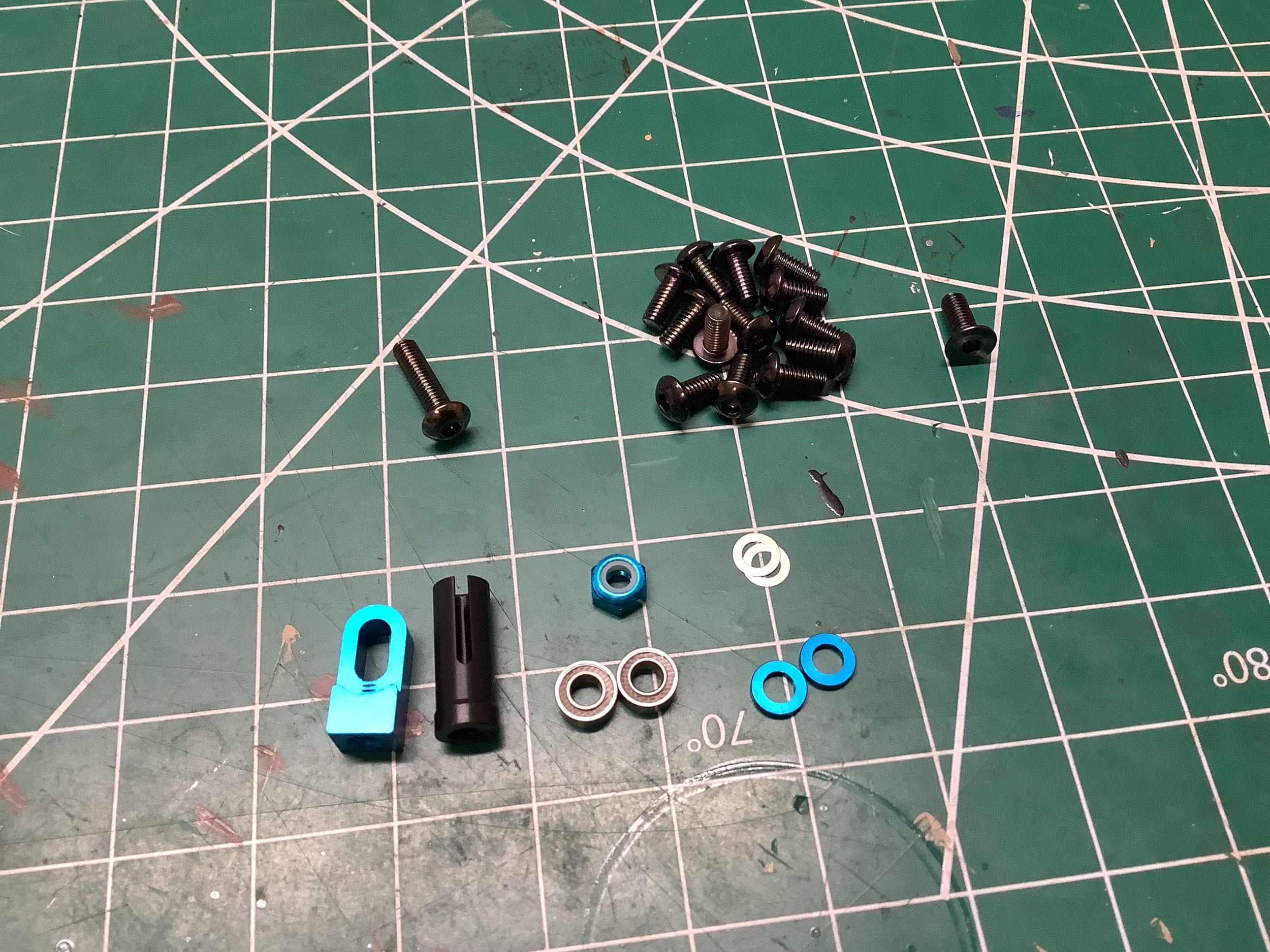
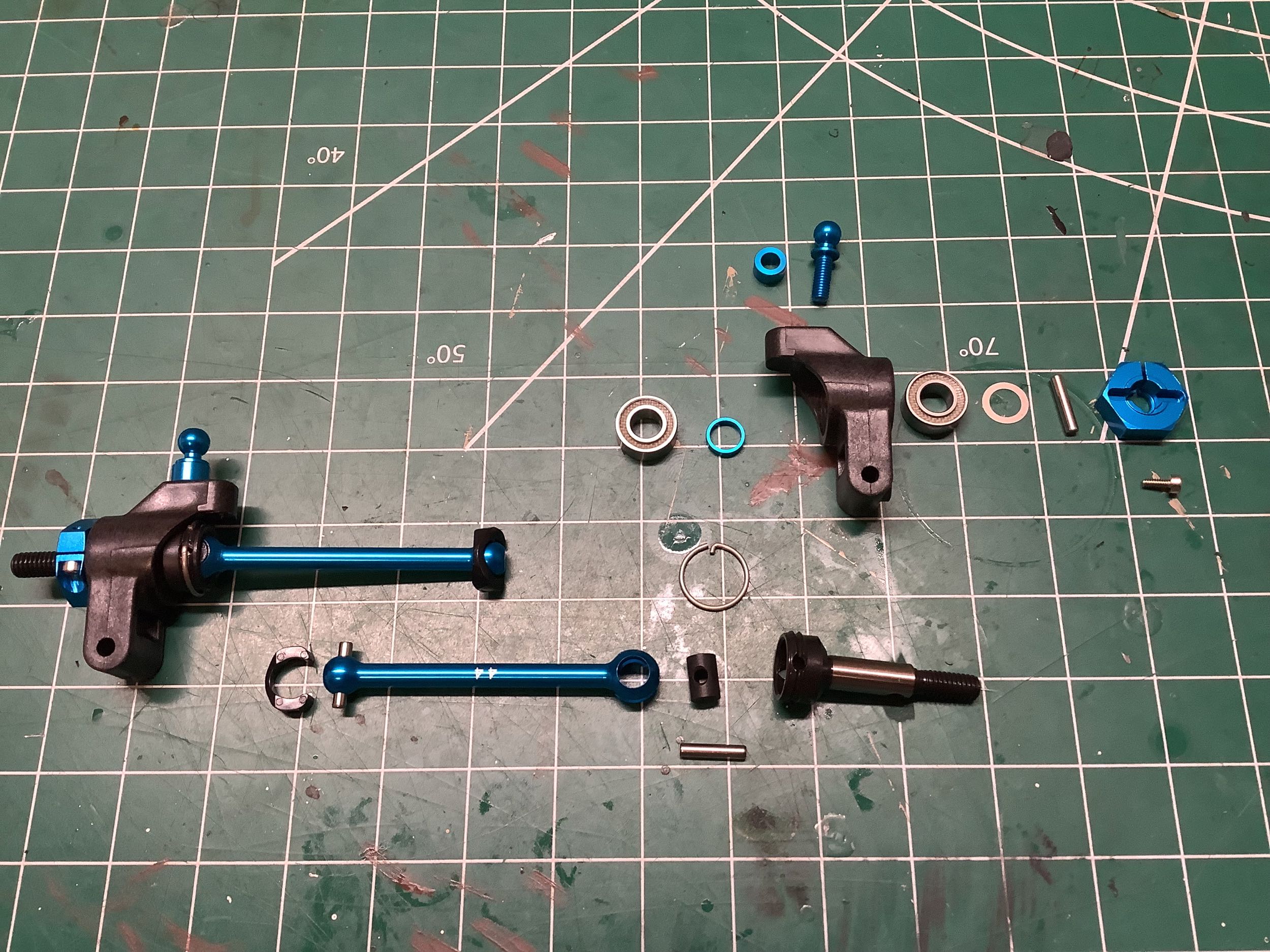
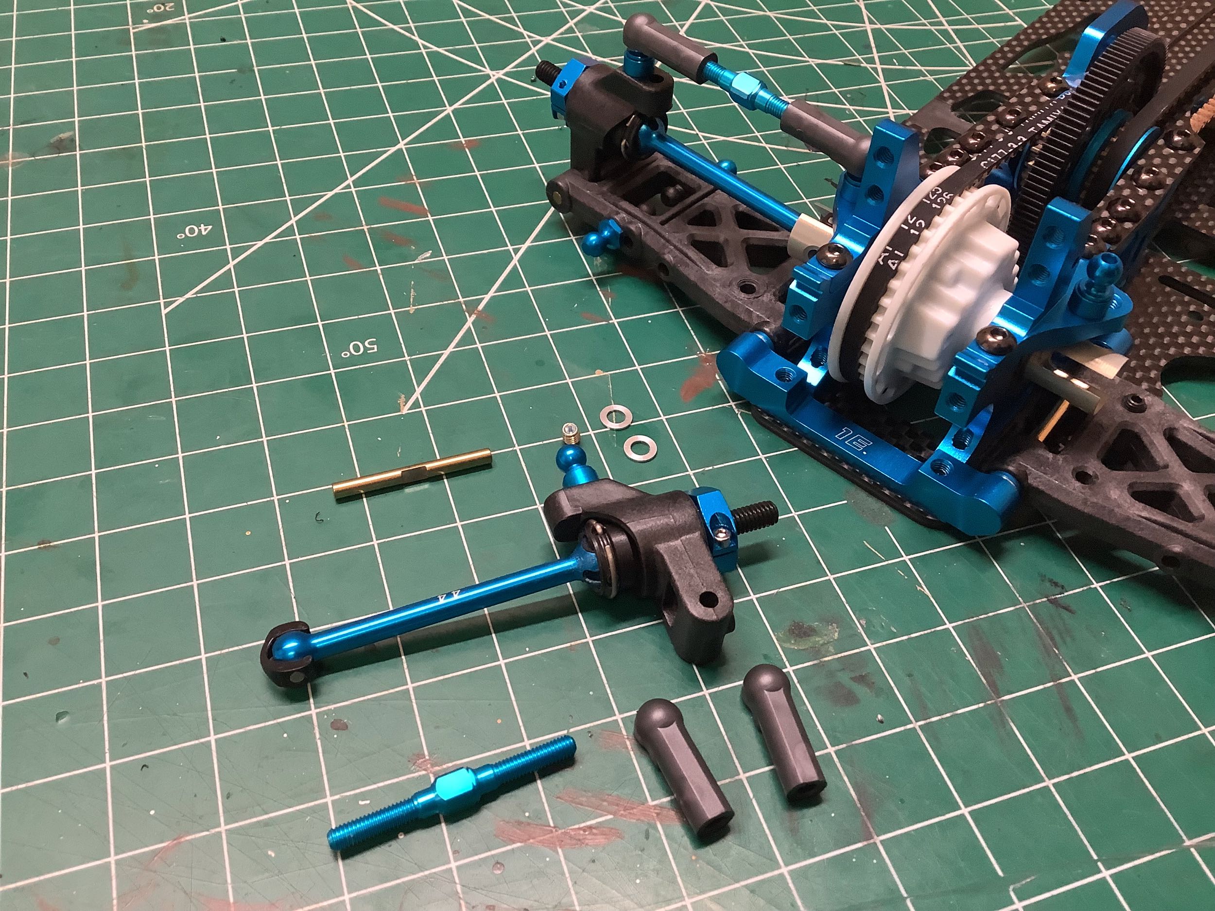
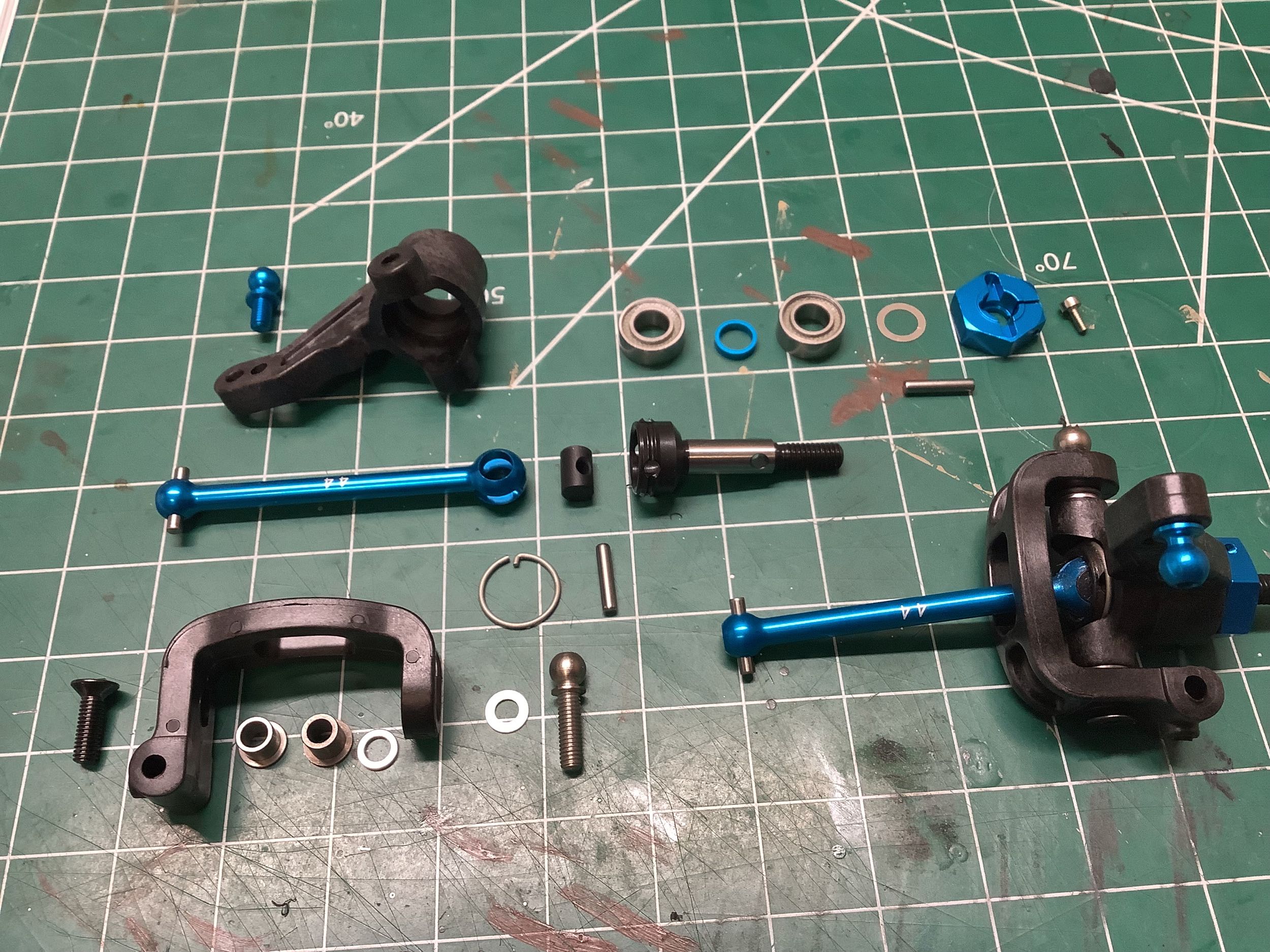
The uprights have not changed, but the CVD axles have. Whereas the
TRF 416 axles retained the cross pin with a set screw, the TRF 417
axles use a circular retaining ring with a tang that clips into a hole
in the axle. These retaining rings are installed symmetrically on
the left and the right so that their direction of spin tends to keep
them installed rather than loosen them. The clamping wheel hexes
have stayed the same.
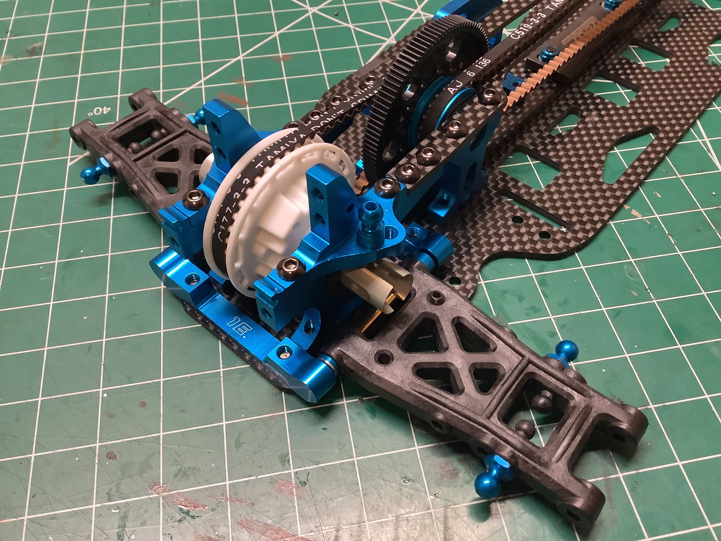
As previously discussed, the front arms have also been changed.
Here the integral plastic ball joints are being used to connect to the
vertical rods for the sway bars. The plastic balls are 4mm (versus
5mm for the aluminum versions), so smaller ball cups (black) need to be
used, and the larger cups (gray) at the other end need to be trimmed to
fit.
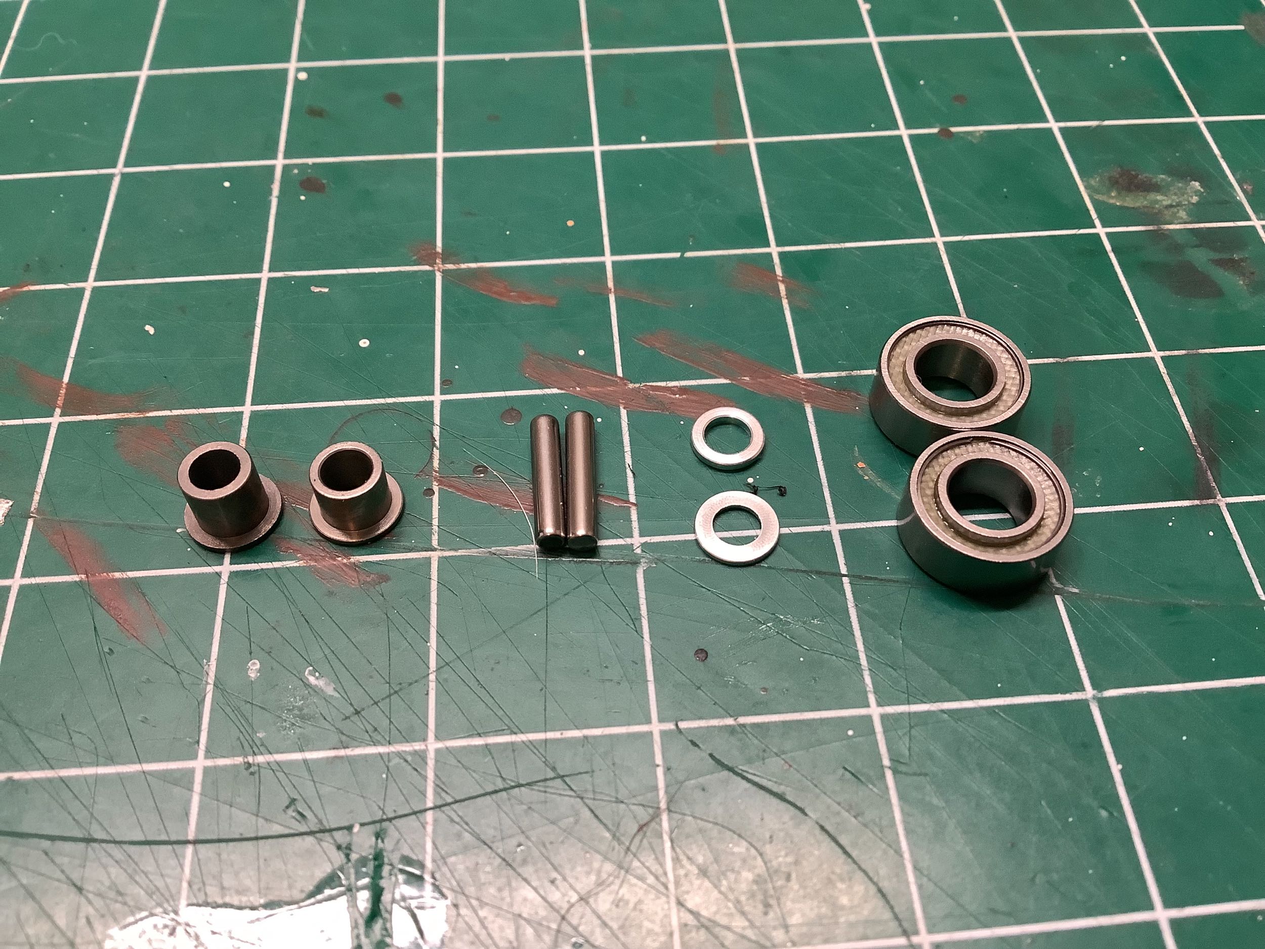
Here's a closer look at some interesting parts of the front
suspension. Can you spot the
difference between those bushings (left)? Probably not because one
of
them is 4.5x3.5mm and the other is 4.6x4.7mm (both with a 3mm
bore). The difference in
height may have some explanation, but why the 0.1mm difference in
outer diameter? Is it to prevent installing the larger one in the
wrong
hole? Nope, the hole tolerances are such that it fits
anyway. The primary effect is that it is really easy to get them
wrong when building the front suspension which uses one for the upper
kingpin and the other for the lower. These parts are carried over
from the TRF 416. Can you spot the
difference between those pins? Probably not because one is 2x9.8mm
and the other is 2x10mm. The shorter one is used in the CVD
axles and the longer one to drive the wheel hex. The length of the
shorter one is presumably dictated by fitting inside the
retaining ring. Why not make all four 9.8mm? Probably
because no one makes 9.8mm pins so Tamiya has to cut them down from
standard 10mm pins. That's my guess anyway. Can you spot the
difference between those two shims? Probably not because one is
0.5mm thick and the other is 0.7mm thick. Unless you have a
digital caliper (which I don't), it is pretty hard to figure out which
is which. The thicker one is a spacer for the steering knuckle, so
inadvertently installing the thinner one instead will introduce some
vertical play. The thinner one is a spacer for the upper ball
joint. The bearings are shown just to highlight the light gray
annular rings which identify these as fluorine sealed bearings, the best
that Tamiya makes.
The hub carriers (F-parts with integrated 4° caster angle) are carried
over from the TRF 416 which in turn came from the TA-05 IFS. The
steering knuckles (C-parts) are also from the TRF 416. Only the CVD
axles have changed by introducing the retaining ring.
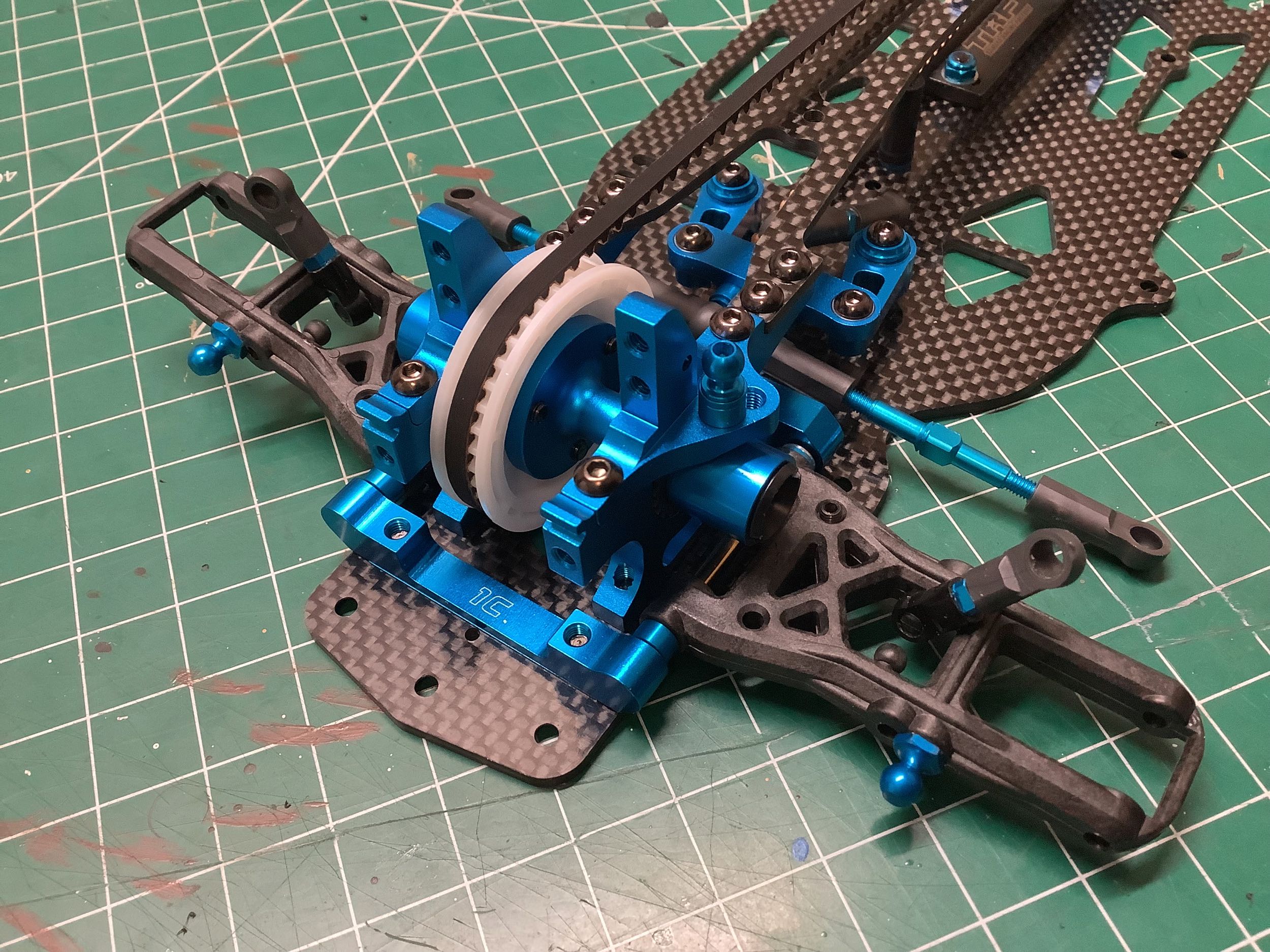
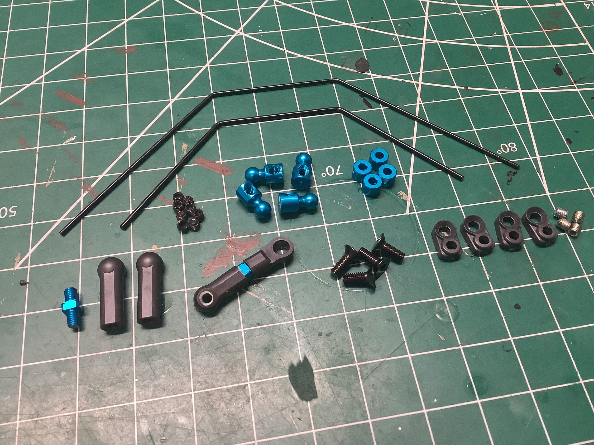
While the sway bar system appears to be identical to that used on the
TRF 416 with a soft rear stabilizer and medium front stabilizer rod, the
part numbers are different. Other stiffnesses are possible but
not included in the kit.
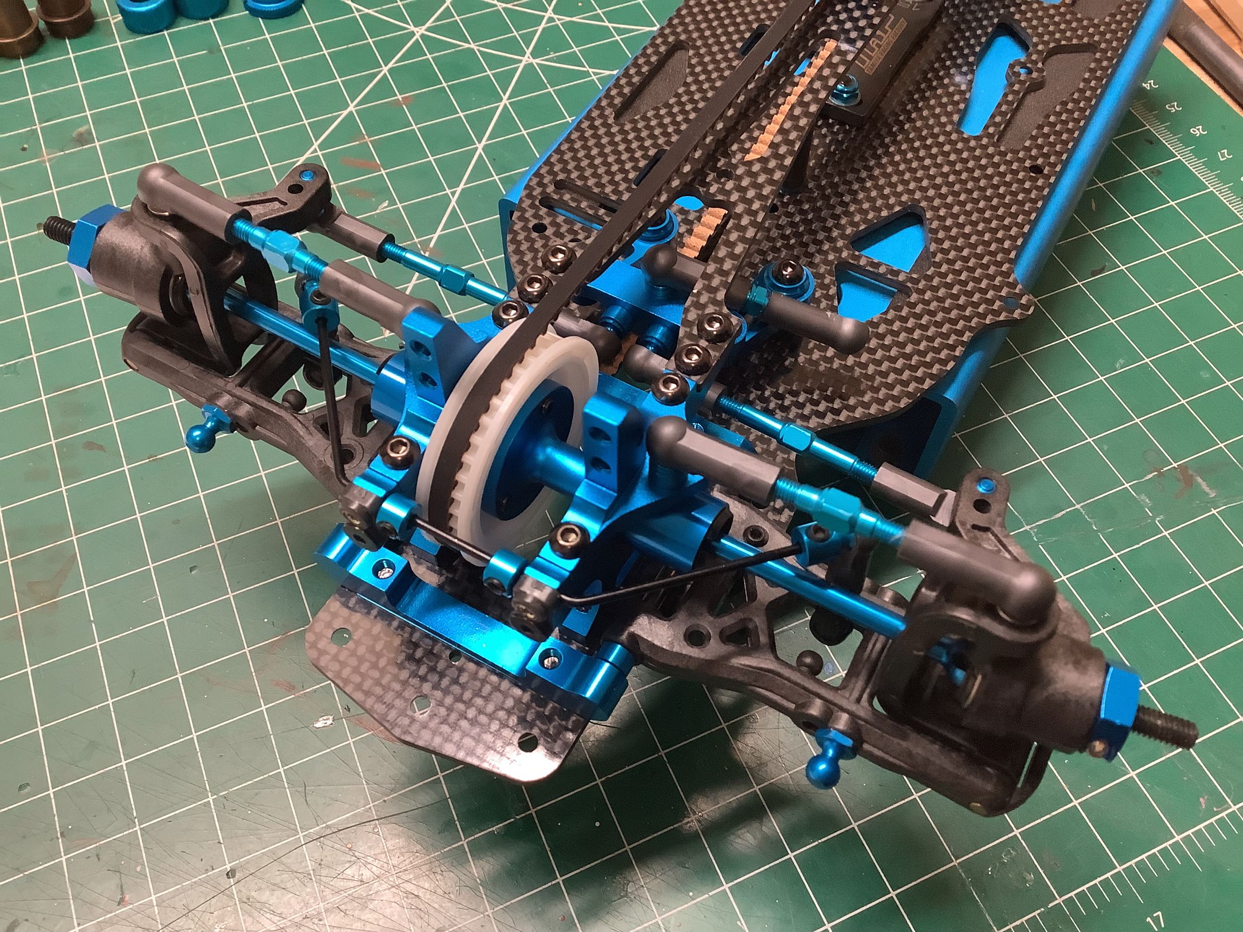
These photos show the completed front sway bar installation (left), and
rear sway bar installation (right). Like all of the other TRF sway
bar installations up to this point, I find that they are not very
effective due to insufficient support at the pivot axis.
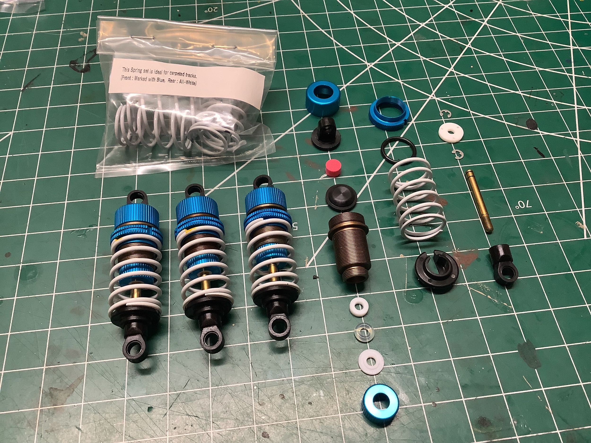
Time to build the shocks which is always one of my favorite parts.
These TRF Special Dampers are the same size and use most of the same
parts as the TRF 416 dampers, but with very subtle differences.
The position of the rod seal and rod support ring have been swapped
(same parts, different assembly position). The TRF 417 also uses
the HL (High Lubrication) version of the cylinders which have a special
coating on them for reduced friction. This is visible as a slight
bronze color on the cylinder versus black on the TRF 416. Finally,
my copy of the kit included "bonus parts" which appear limited to the
extra set of springs shown at upper left. Based on the wire
diameter and pitch, these appear to be stiffer than the stock springs
and are labelled as being for use on carpeted (high traction)
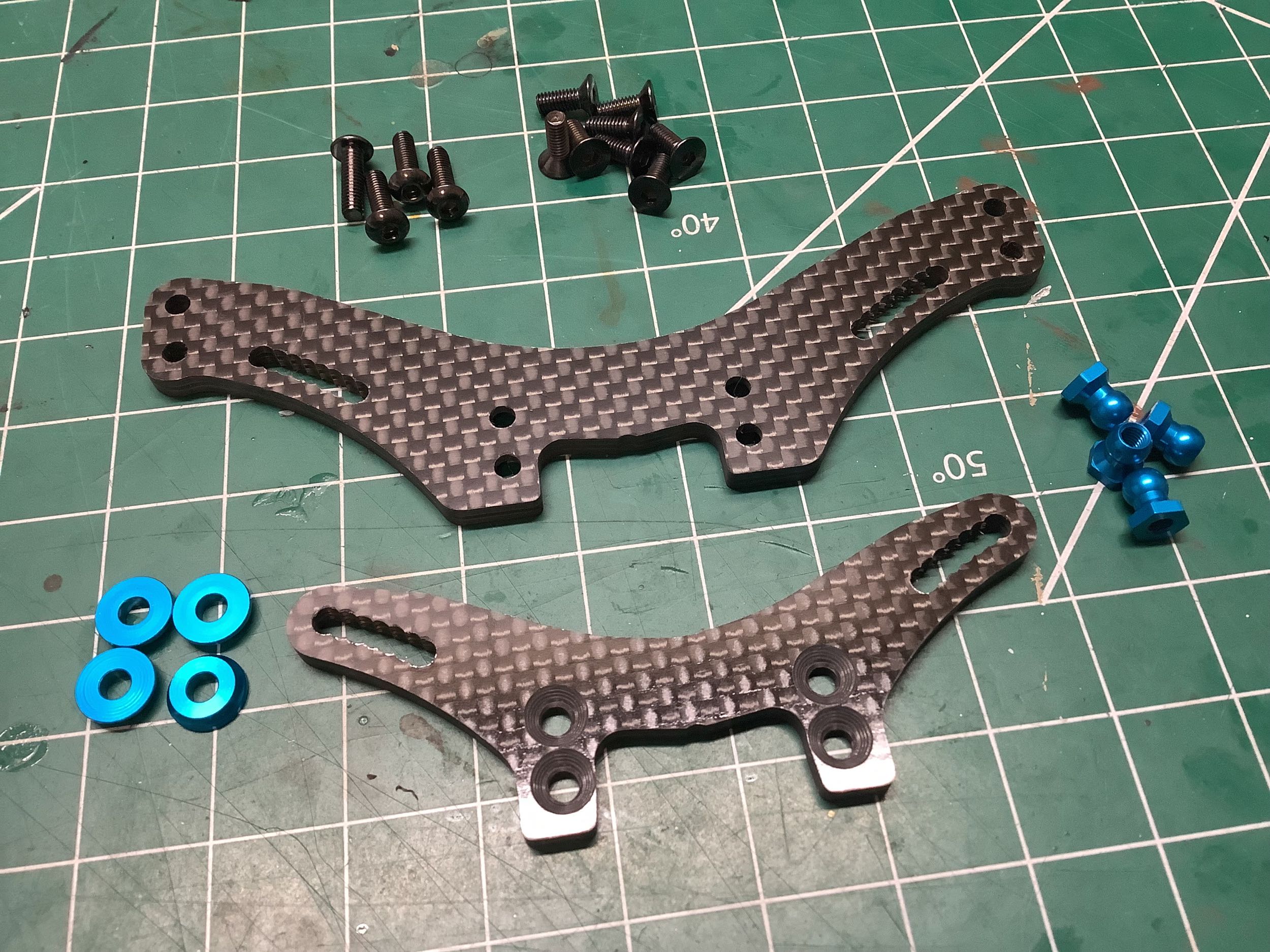
tracks. The carbon shock towers are shown at right. These
have more hole positions that those from the TRF 416, but I'm not a fan
of overlapping holes since they are very structurally weak.
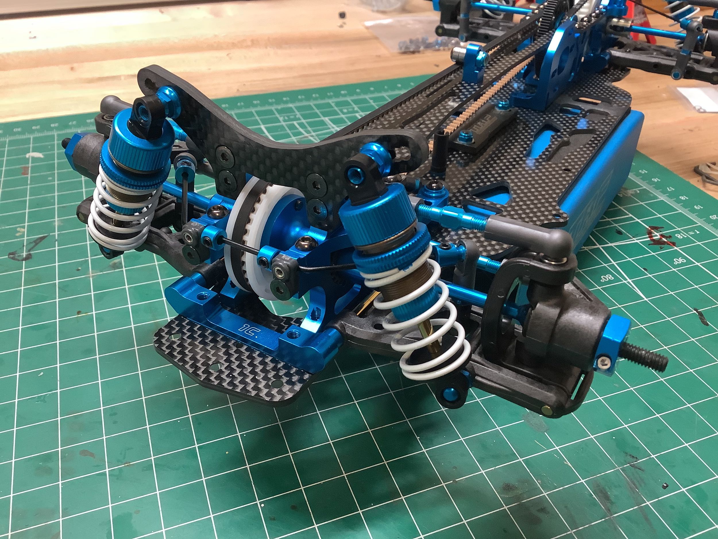
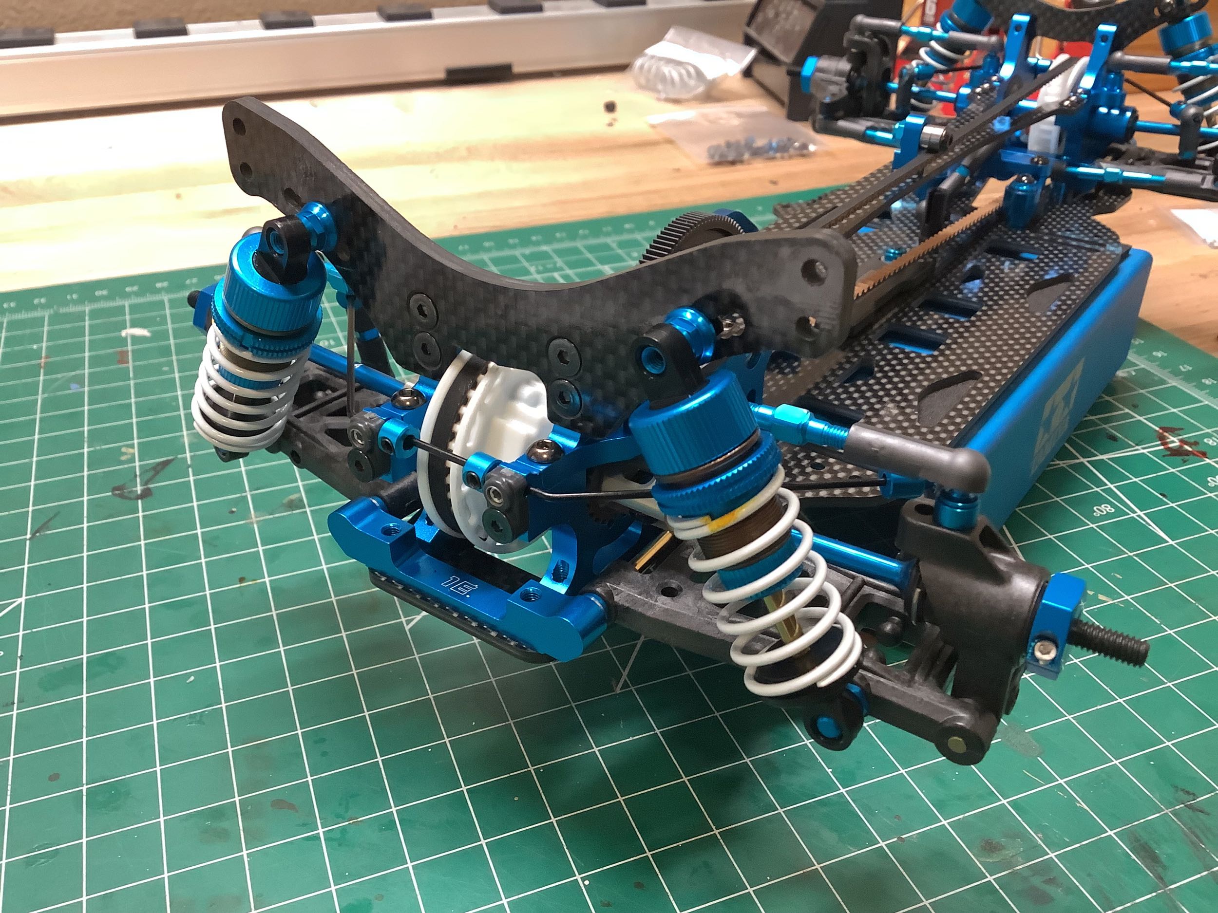
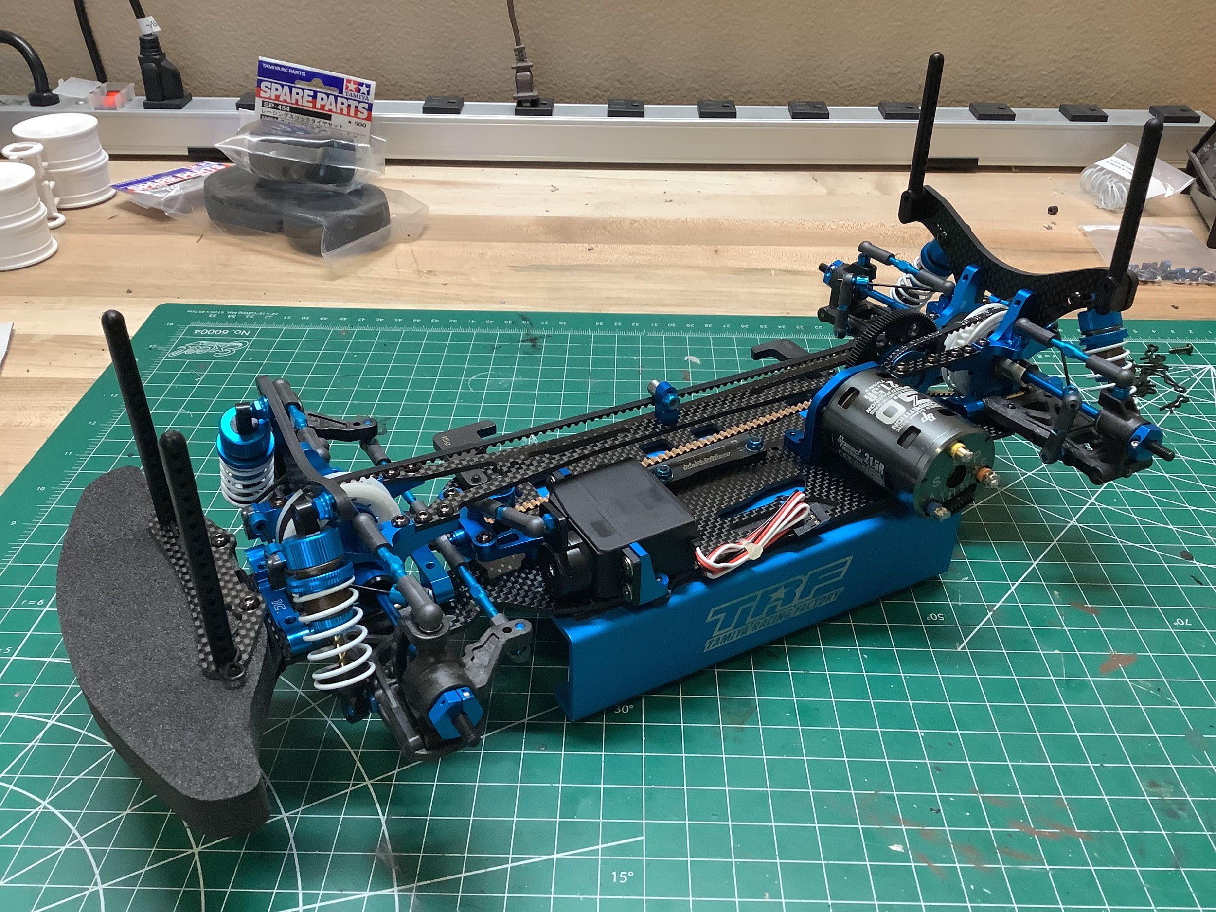
These photos show the completed front (left) and rear (right) suspension
assemblies with the shocks installed. This chassis is complete
apart from the electronics.
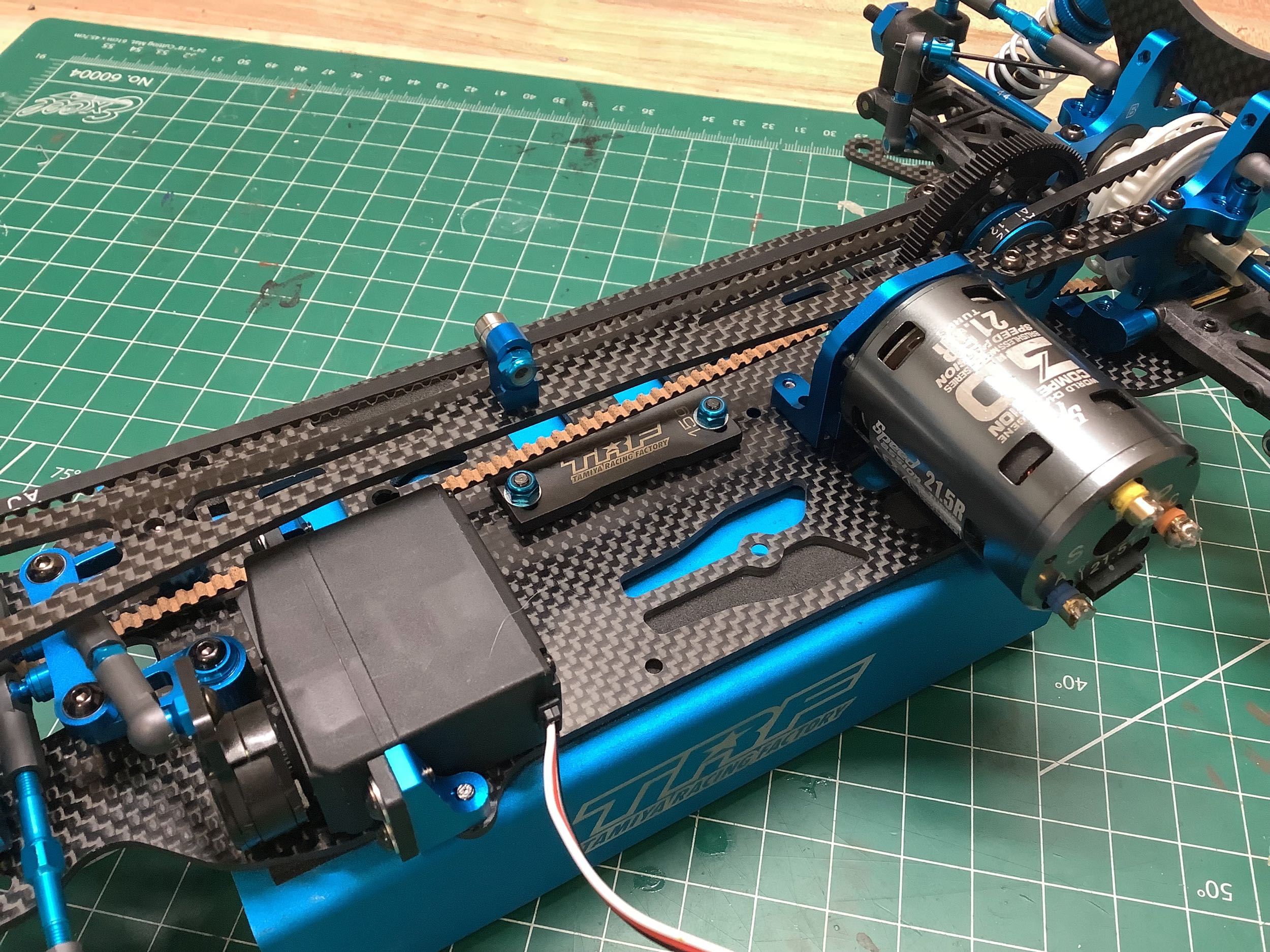
The TRF 417 is the first TRF chassis to have been specifically designed
for brushless motors and hard case racing batteries. I happened to
have an old unused Speed Passion brushless motor which seemed about the
right vintage for this chassis so I installed it. A regular silver can
brushed motor actually won't fit, although other Tamiya brushed motors
(like Super Stock) will. I've also installed a cheap steering
servo just to hold the wheels straight.
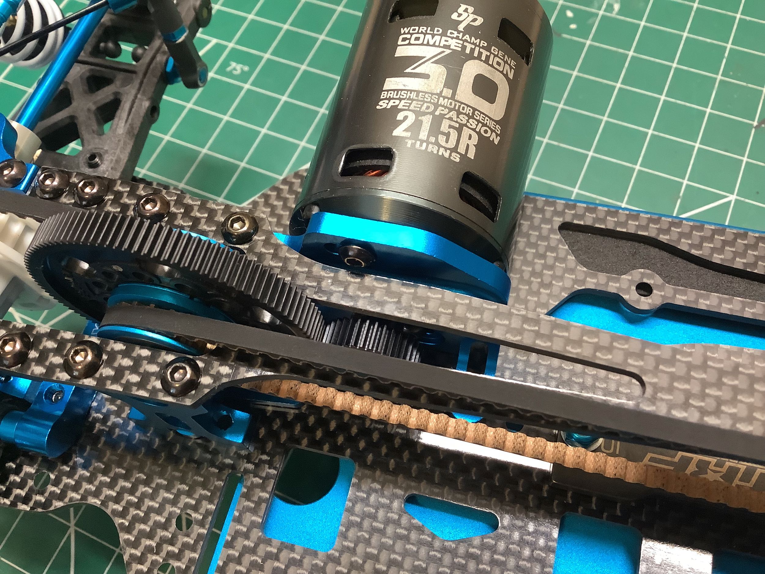
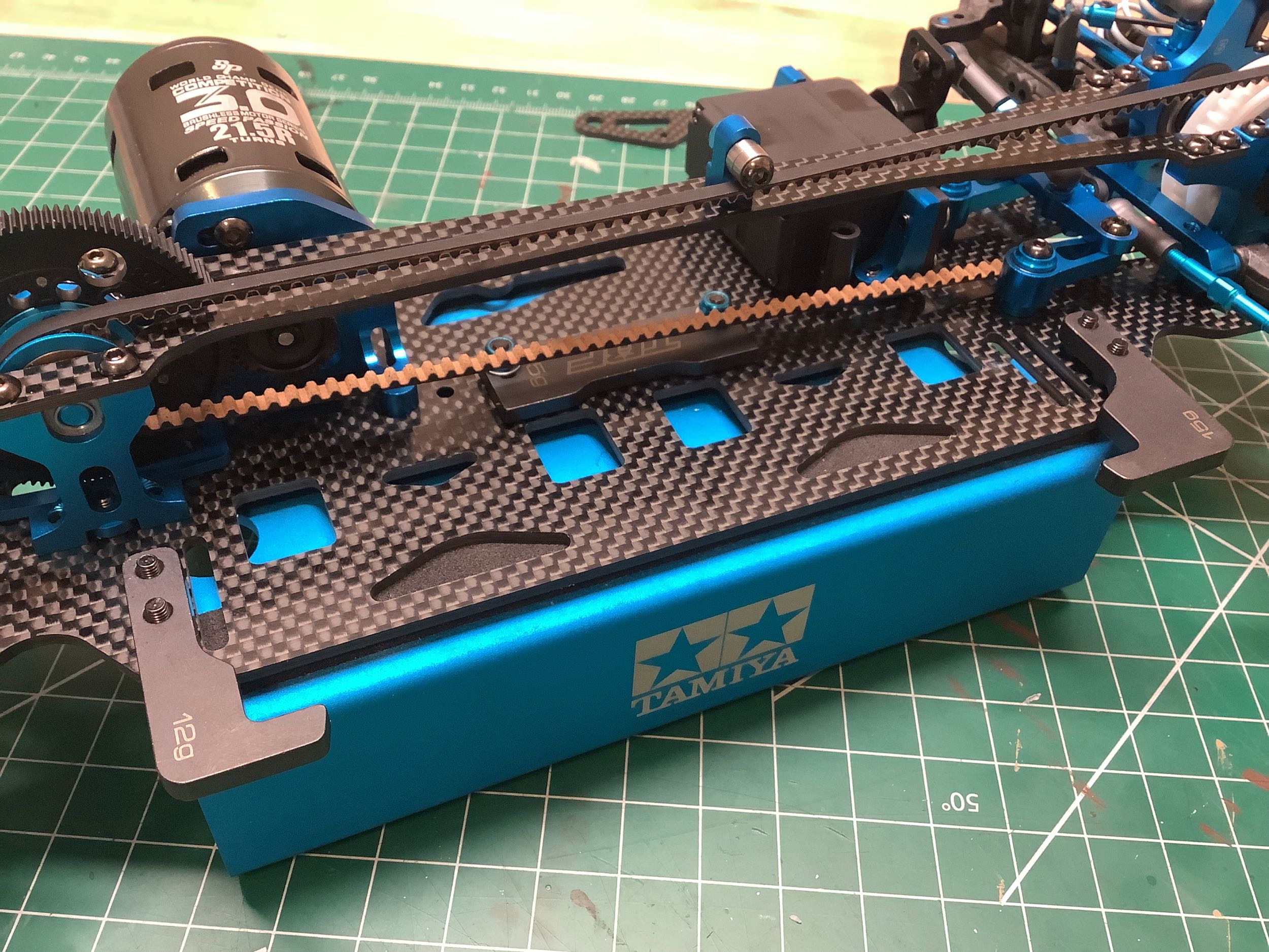
This side view shows the two ways to bolt the motor to the motor
plate. I've used the upper and lower holes which are located
diagonally but are partially blocked the the belt and therefore hard to
access. The other option is to use the center horizontal
holes. If these are used the left hand hole is only accessible by
passing your hex tool through one of the large holes in the spur gear.
The lovely steel battery supports double as12g ballast weights.
They don't provide any vertical support so glass tape is still needed to
secure the battery. The supports are therefore not strictly
necessary to use at all, but they do provide extra lateral
support. I've also added the body posts, front bumper, and carbon
bumper support.
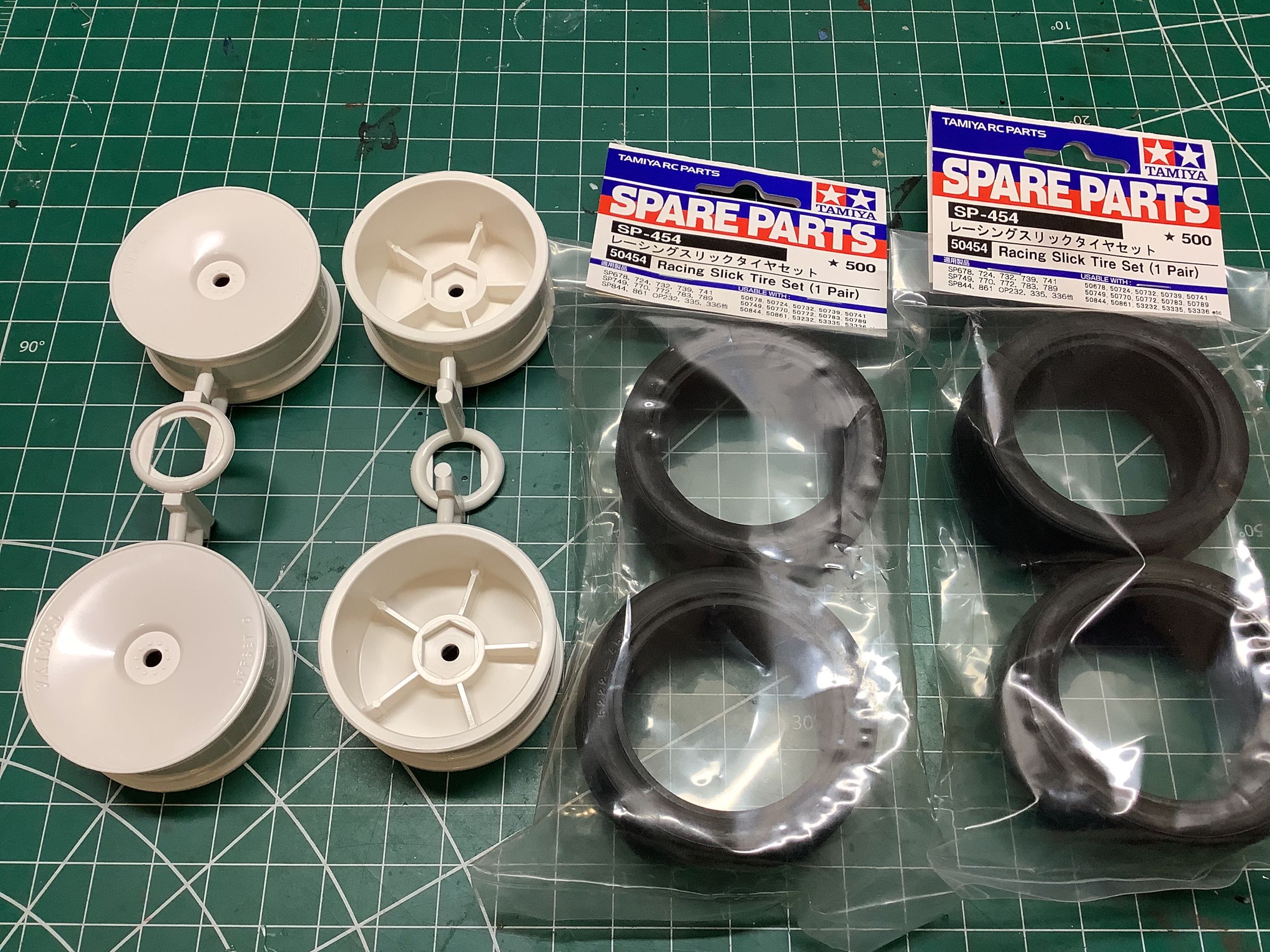
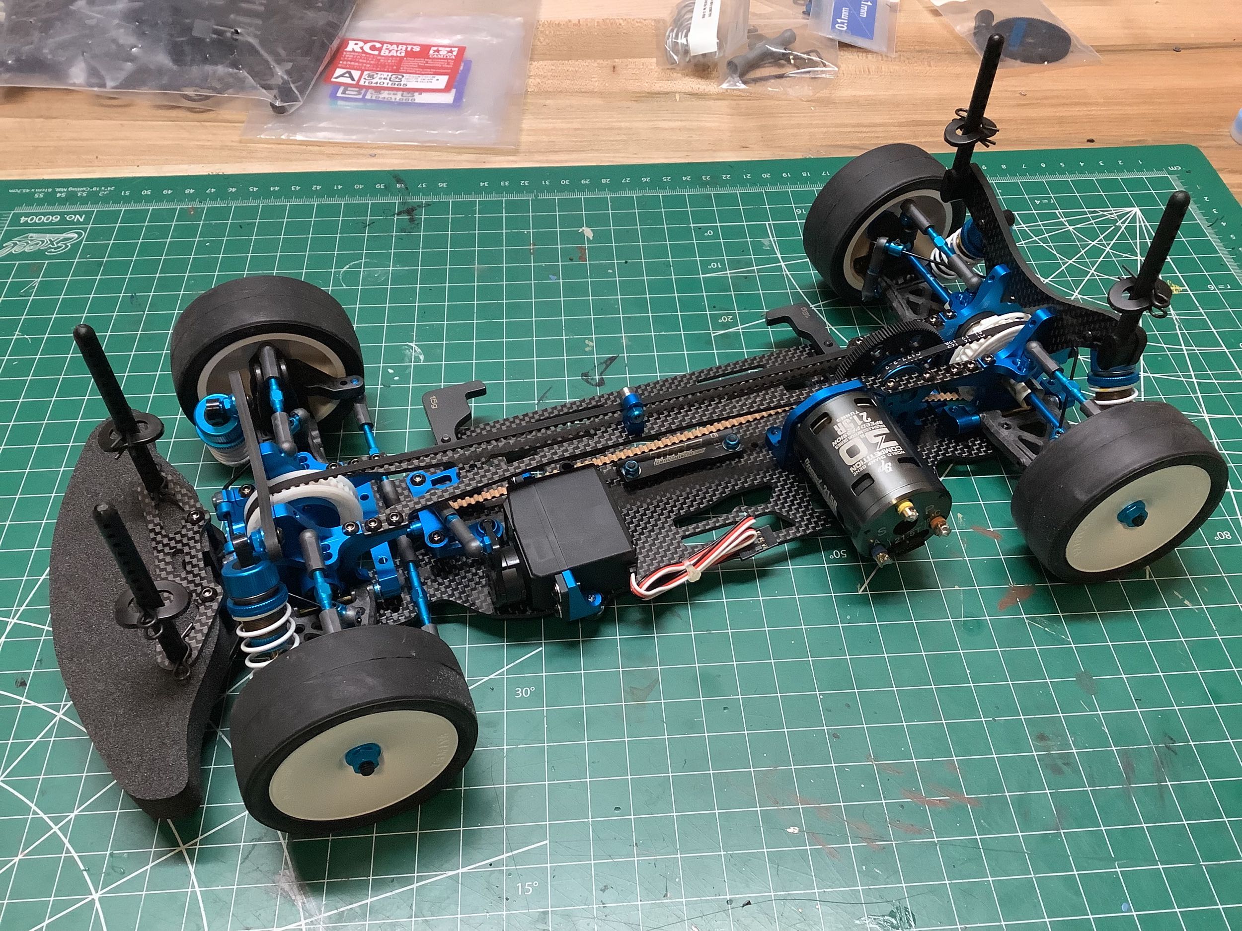
This model came with dish wheels but no tires so I've added a set of
cheap racing slicks to be consistent with my other TRF chassis
models. The completed chassis is shown at the right.
©2024 Eric Albrecht