Tamiya TRF 416 Project
Page 2: Assembling the Chassis
While writing about this build, I am going to concentrate on the
differences between this and the last chassis in the TRF line I built
(the TRF 415MSX).
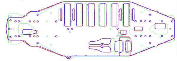
This first picture compares the chassis from the TRF 415MSX (green),
the TRF 416 (blue), and from the 416X (red). Compared to the 415,
you can see that the main differences are moving the motor and the
battery slightly back. The 416 and 416X are virtually
identical. The 416X added a couple of unused mystery holes that I
haven't been able to fully understand. I assume they are for some
kind of maintenance access. I don't have the 416X so I can't
verify.
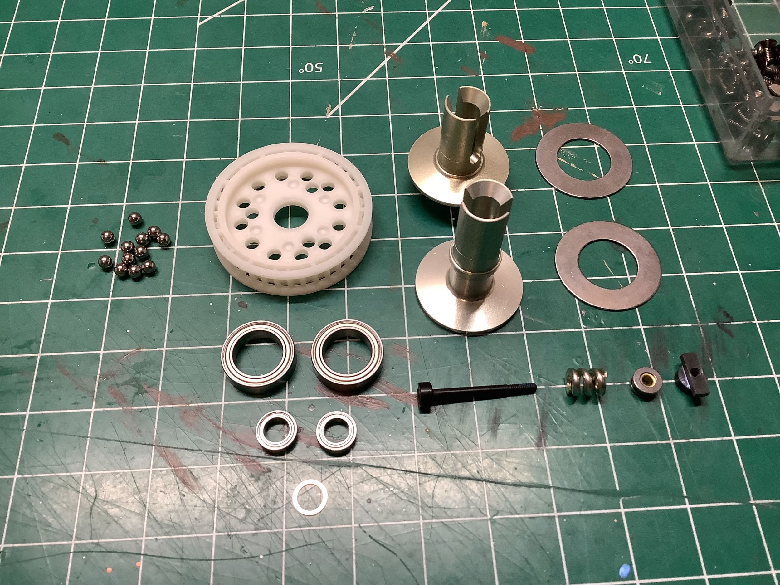
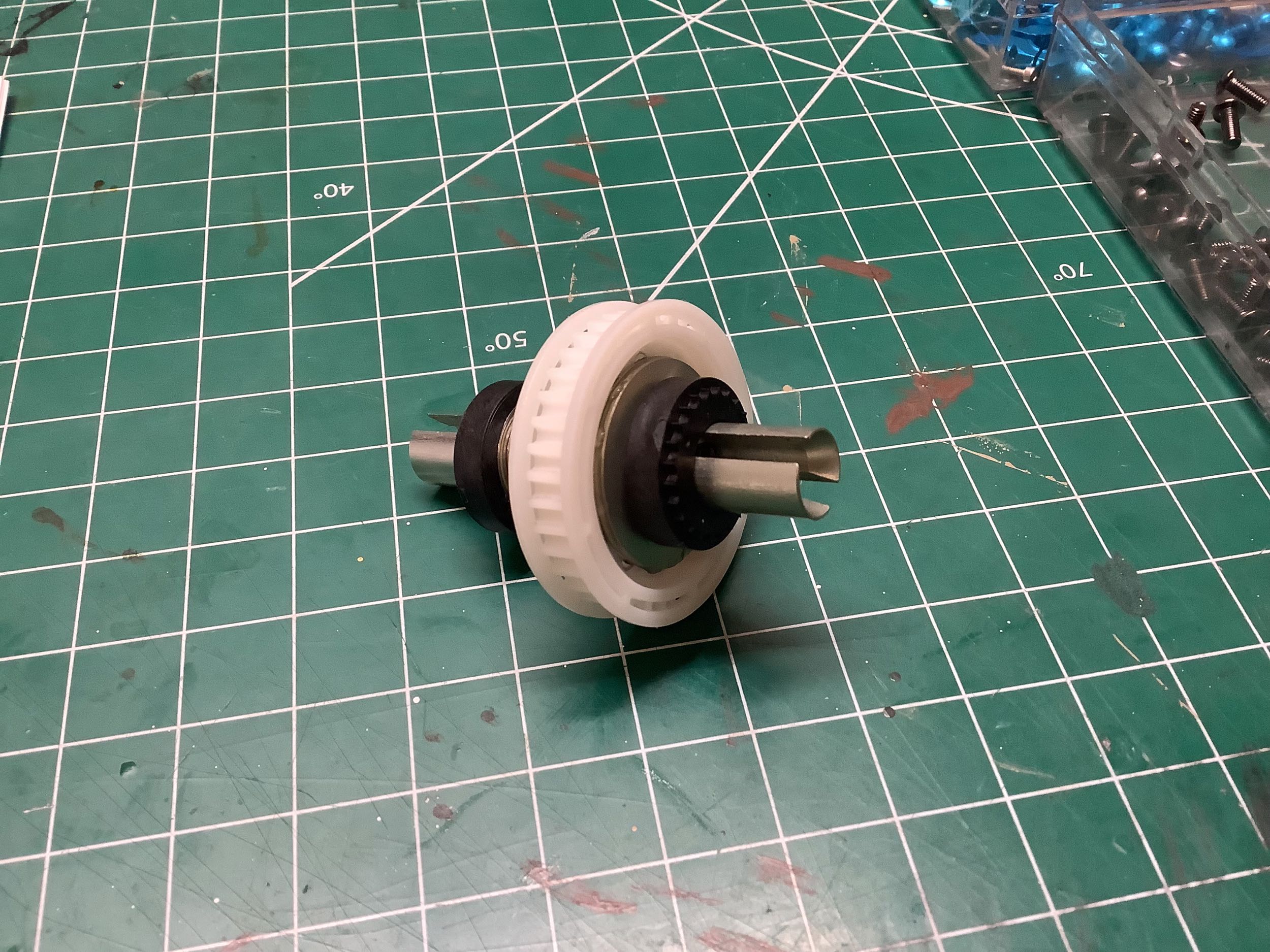
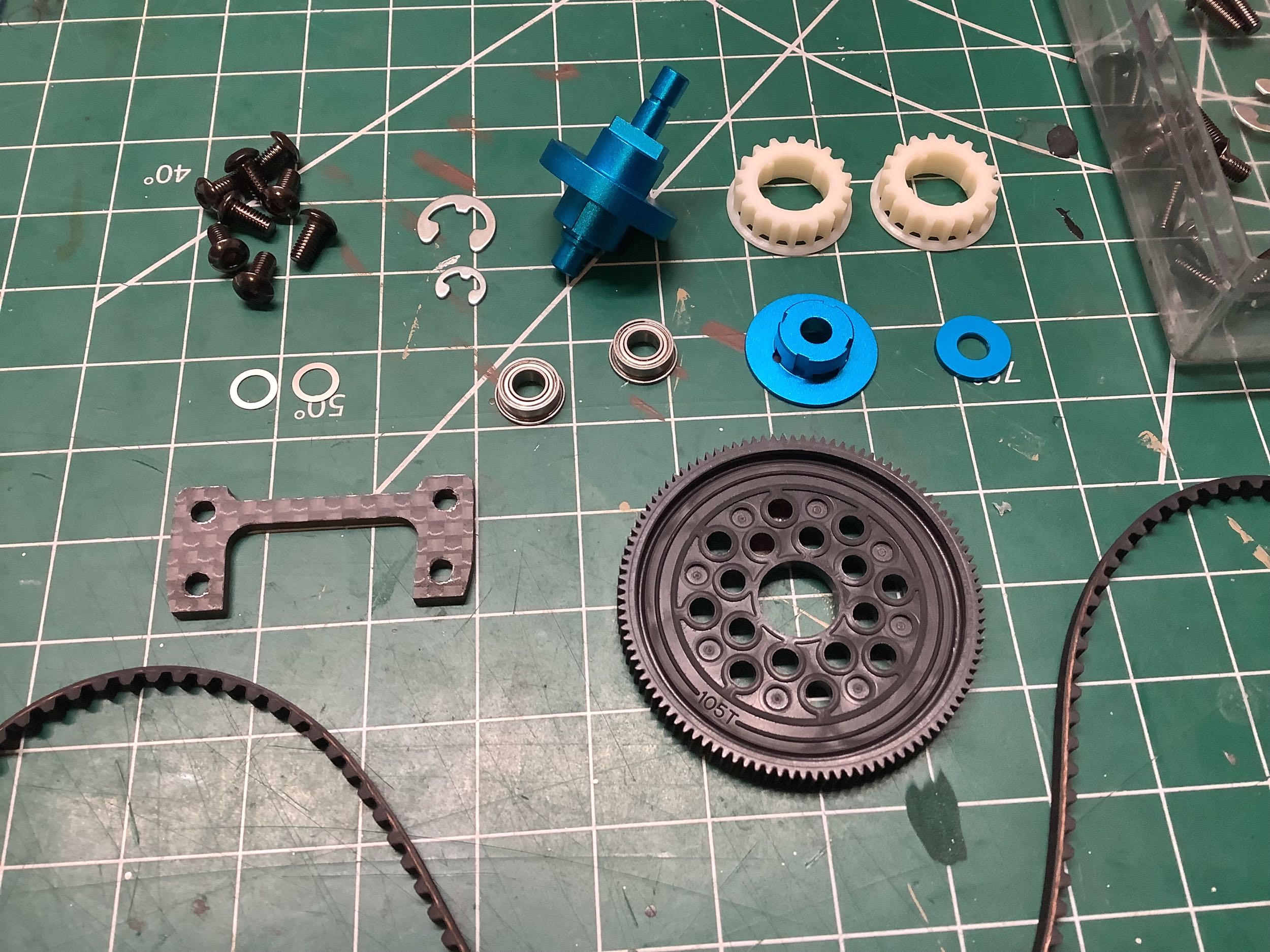
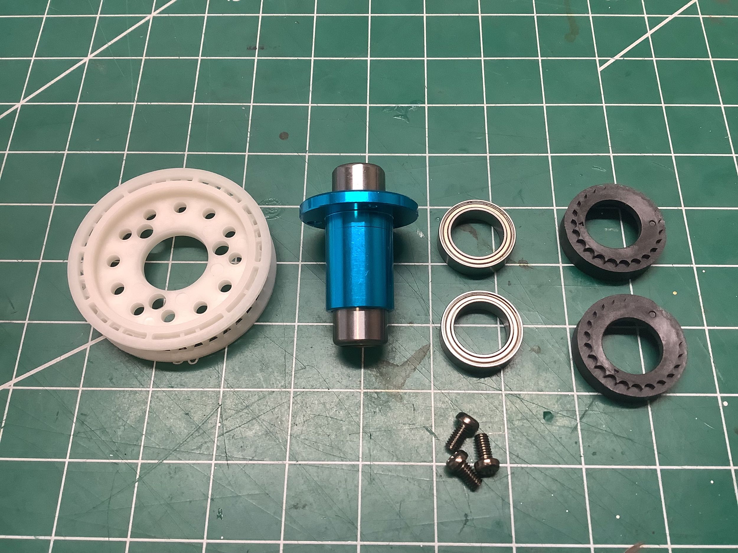
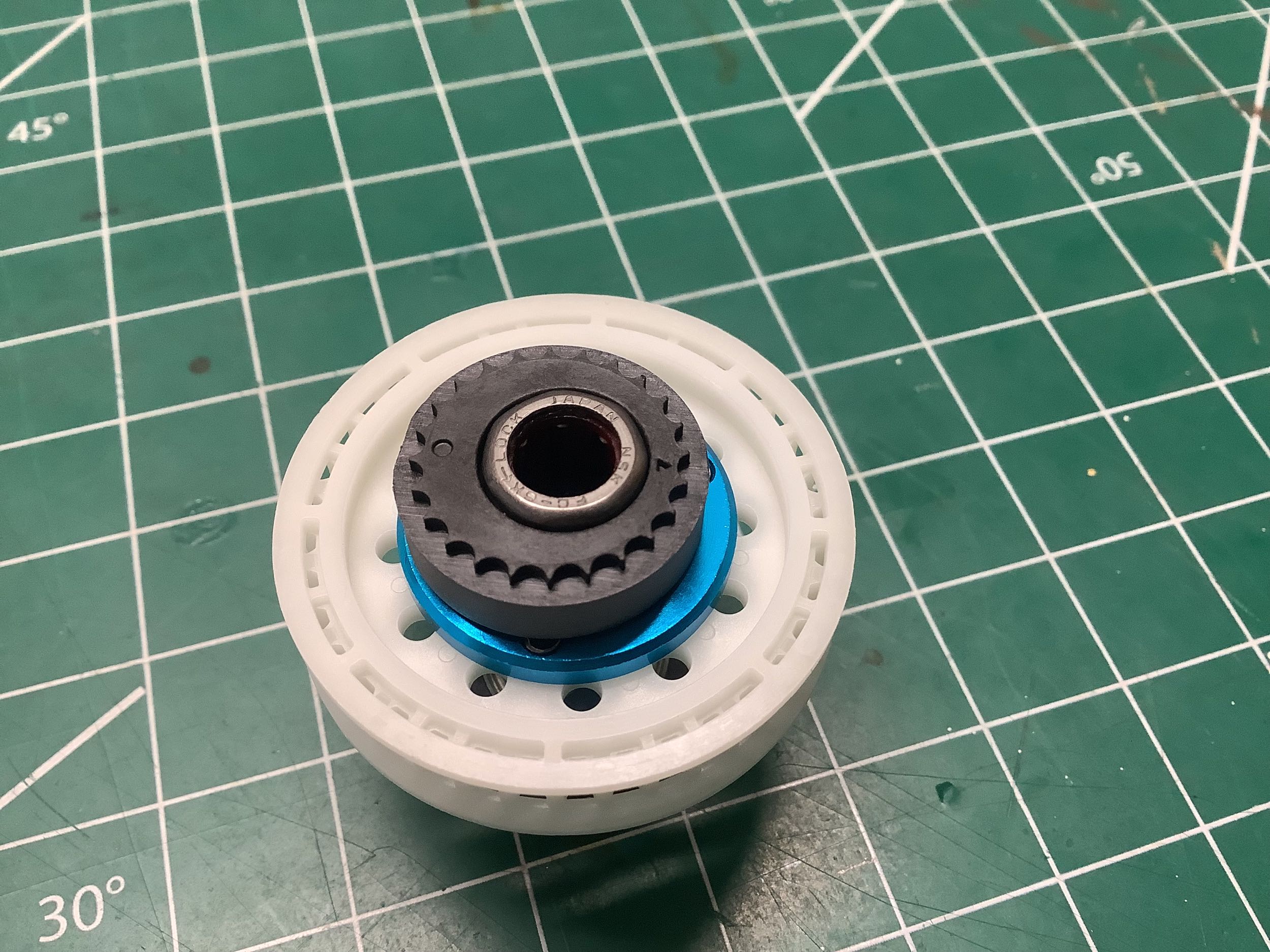
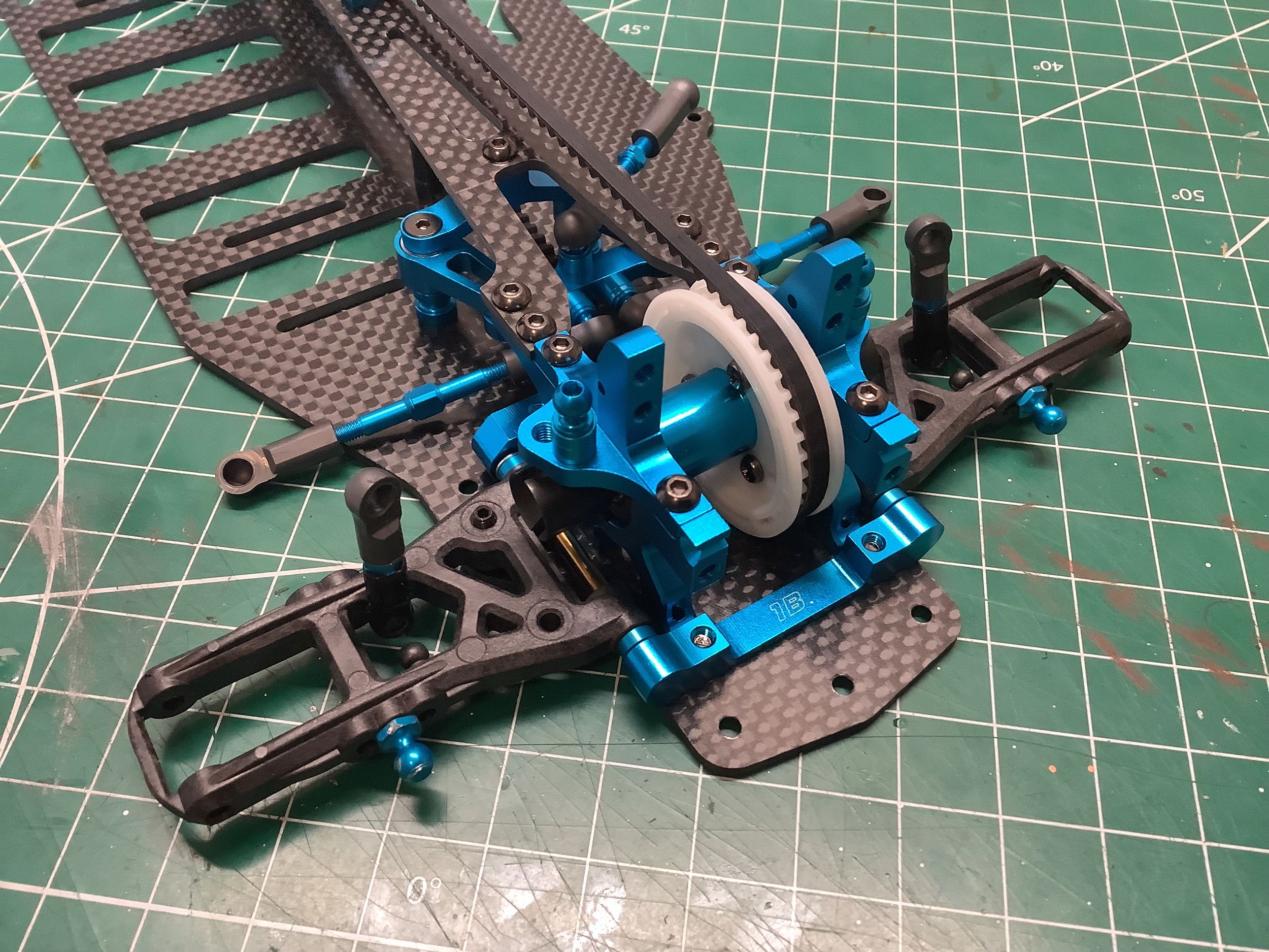
Compared to the TRF 415MSX, this ball differential increases the ball
count from 8 to 12 so it should be quite a bit stronger. Tamiya
has also found a clever way to get rid of that annoying 2 piece pulley
that had to be glued. The new one-piece molded part shown uses
slots in the pulley flange to give the mold access to form the
teeth. It must be an incredibly complex multi-part mold. The
diff nut is also now a special steel part instead of a
standard nut sitting in a plastic housing.
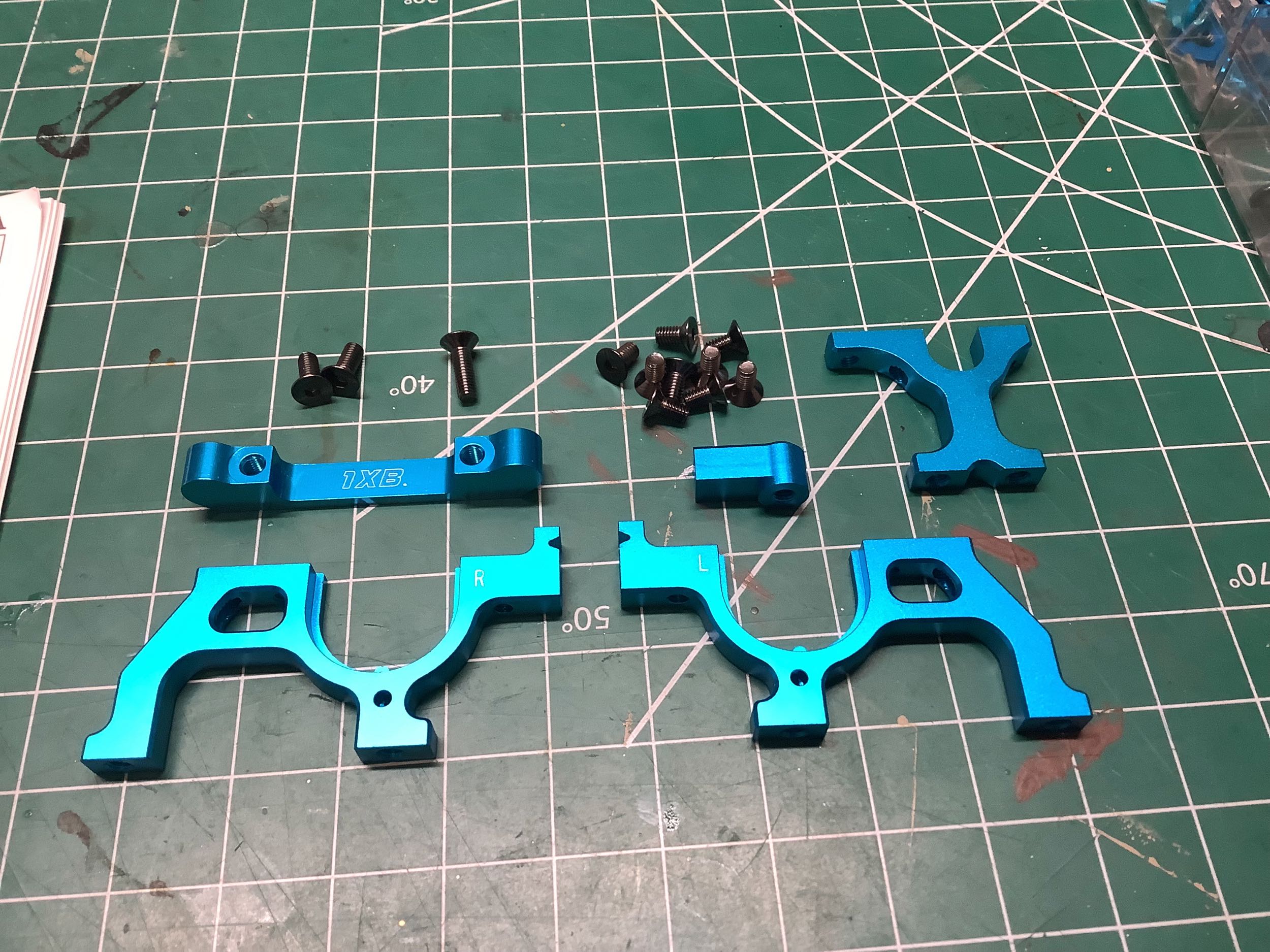
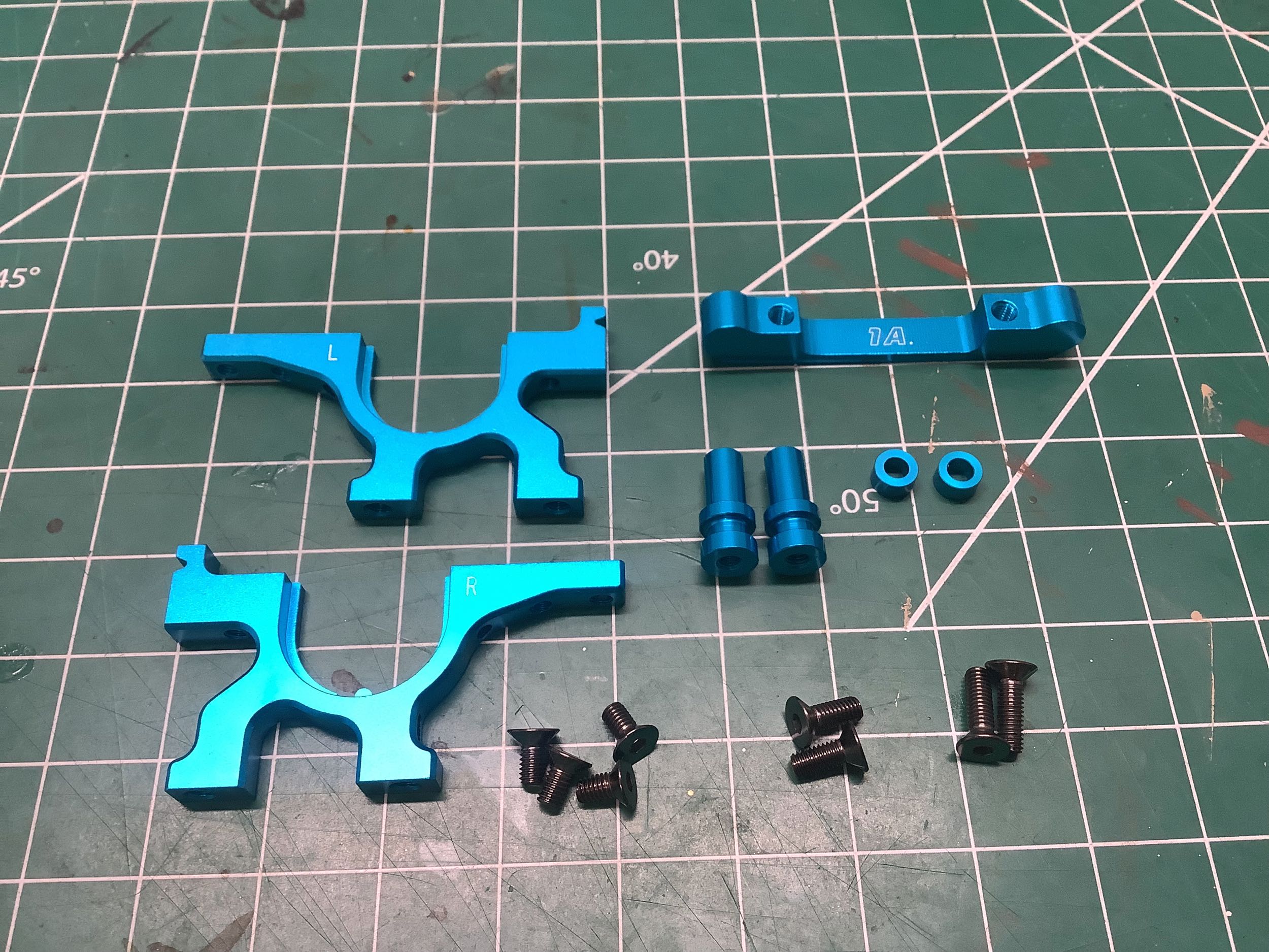
What used to be two rear bulkheads that integrated the motor mount and
the center pulley mount has now split into four parts with separate rear
and center bulkheads. The motor mount includes a side support to
help with the weight of the cantilevered motor. This side support
got even stronger later with the World Edition and 416X. The
forward of the rear suspension mounts is also installed at this
point. The rear bulkheads have been simplified with only a single
tab to integrate with the scalloped eccentric bearing supports on the
ball diff.
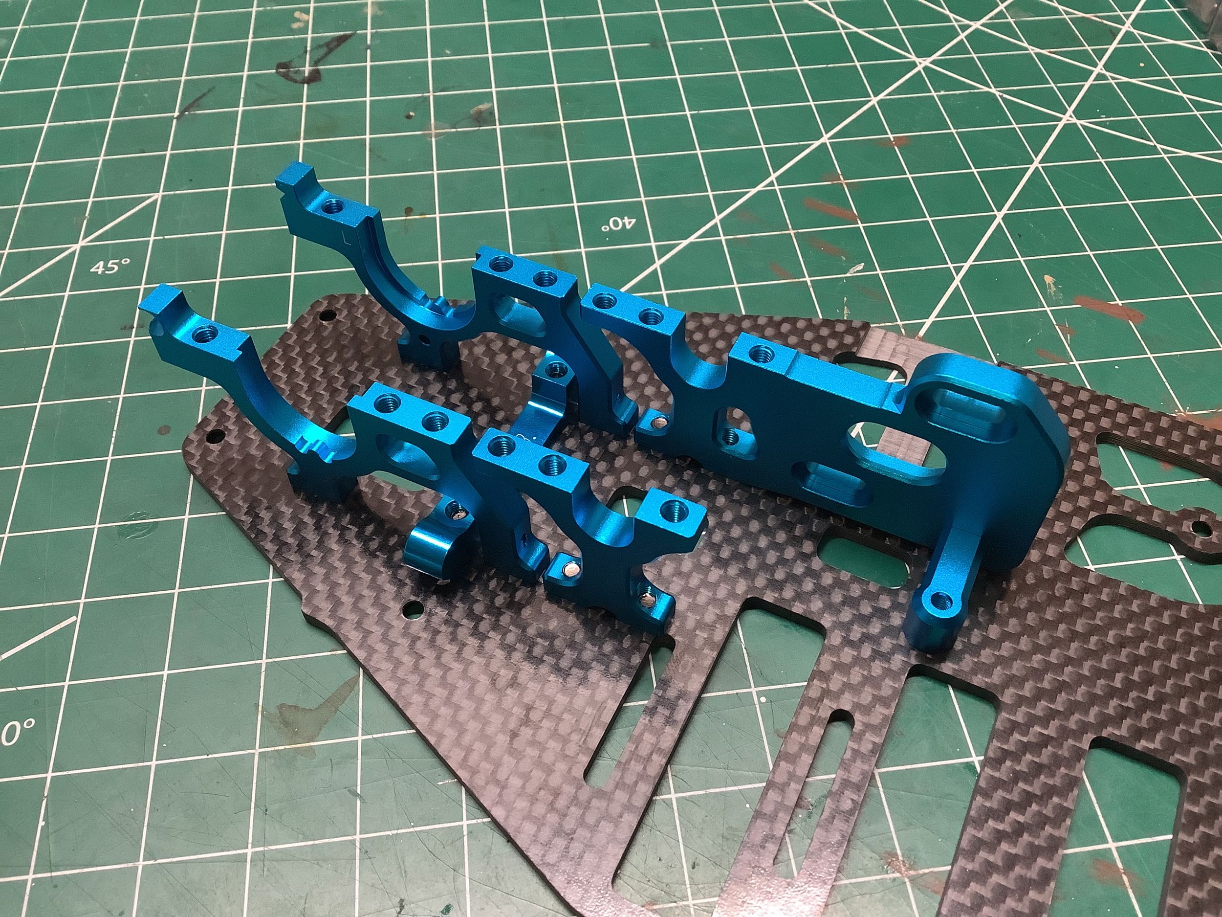
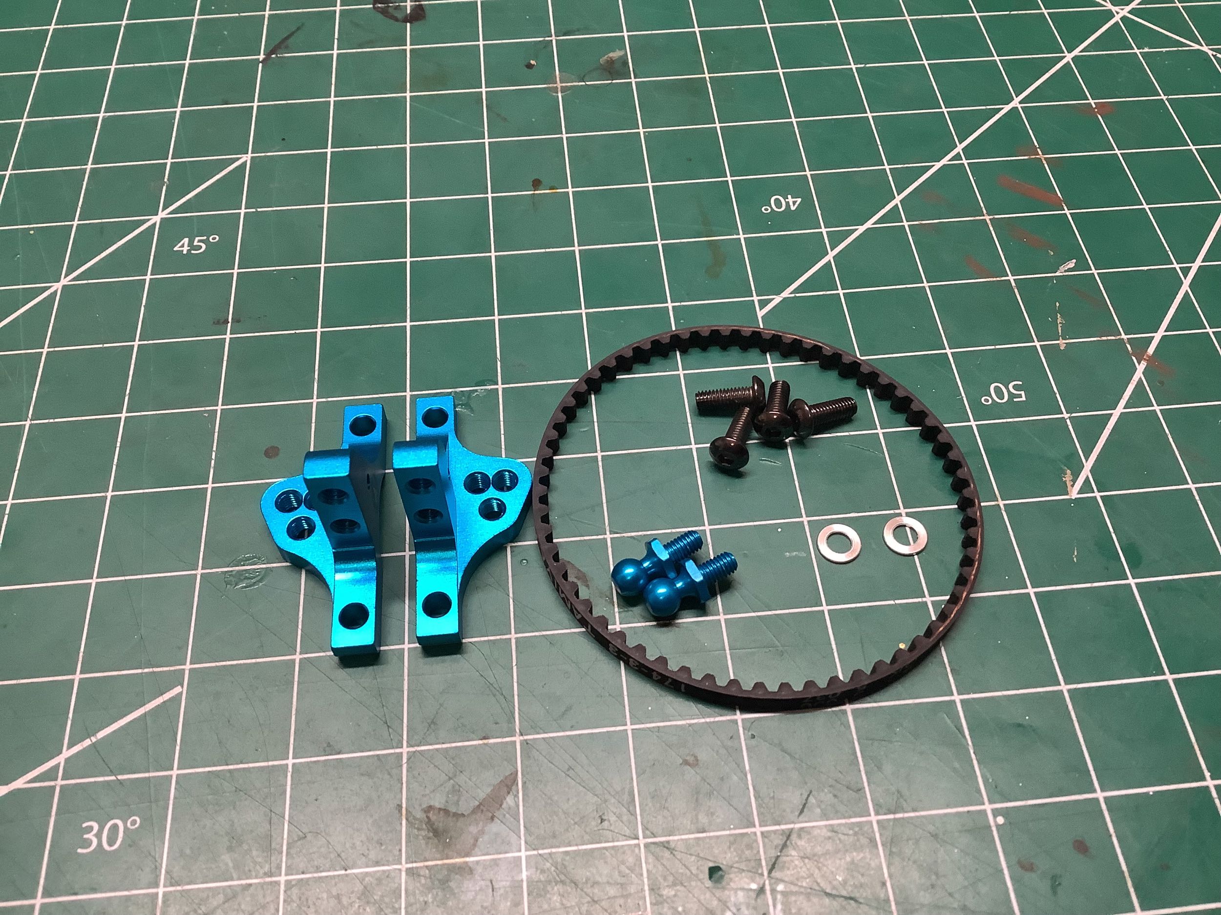
These upper bulkheads are very similar, but not identical, to the parts
from the TRF 415MSX. They capture the rear ball differential and
belt, and will later support the camber links and shock tower.
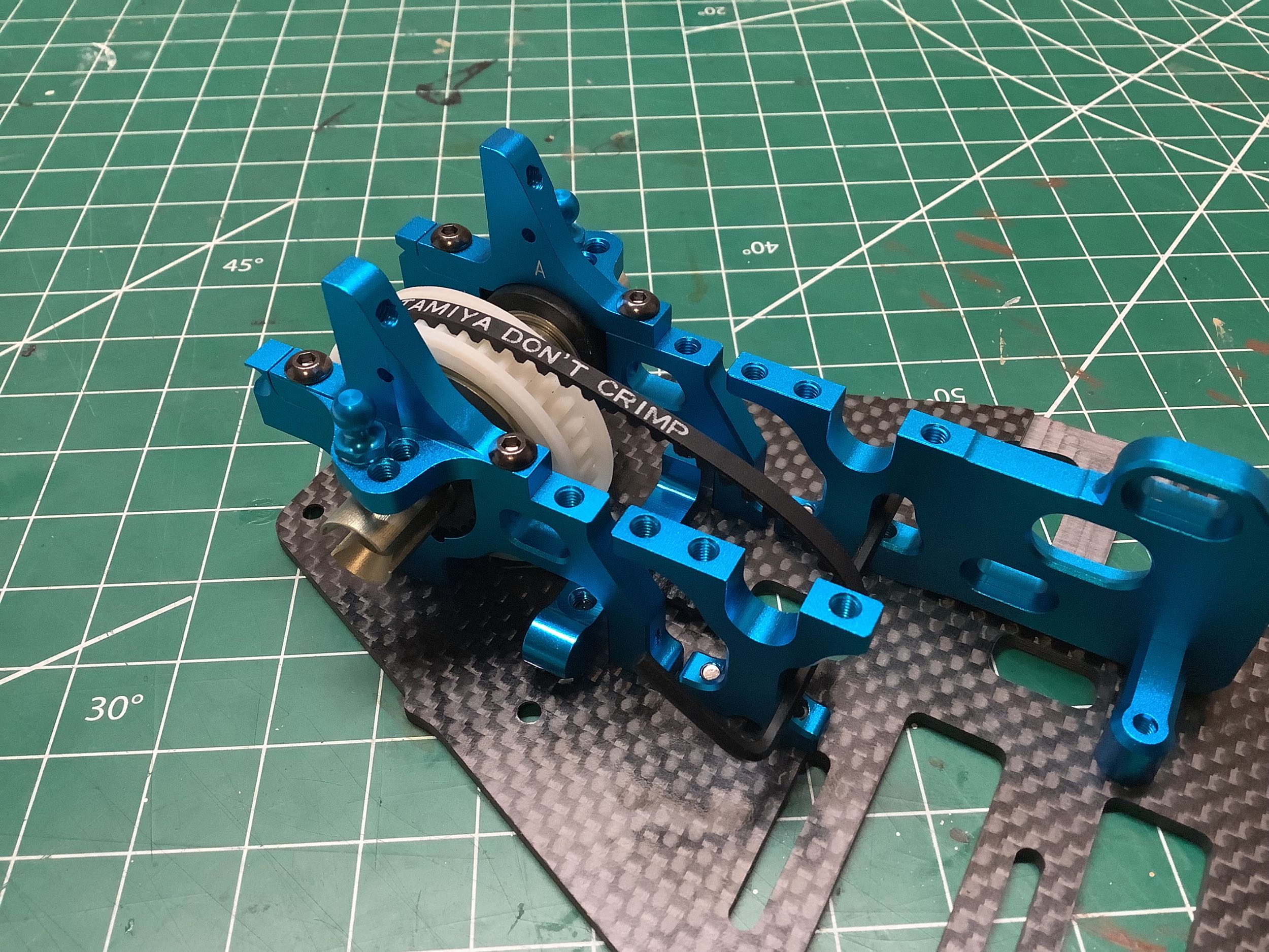
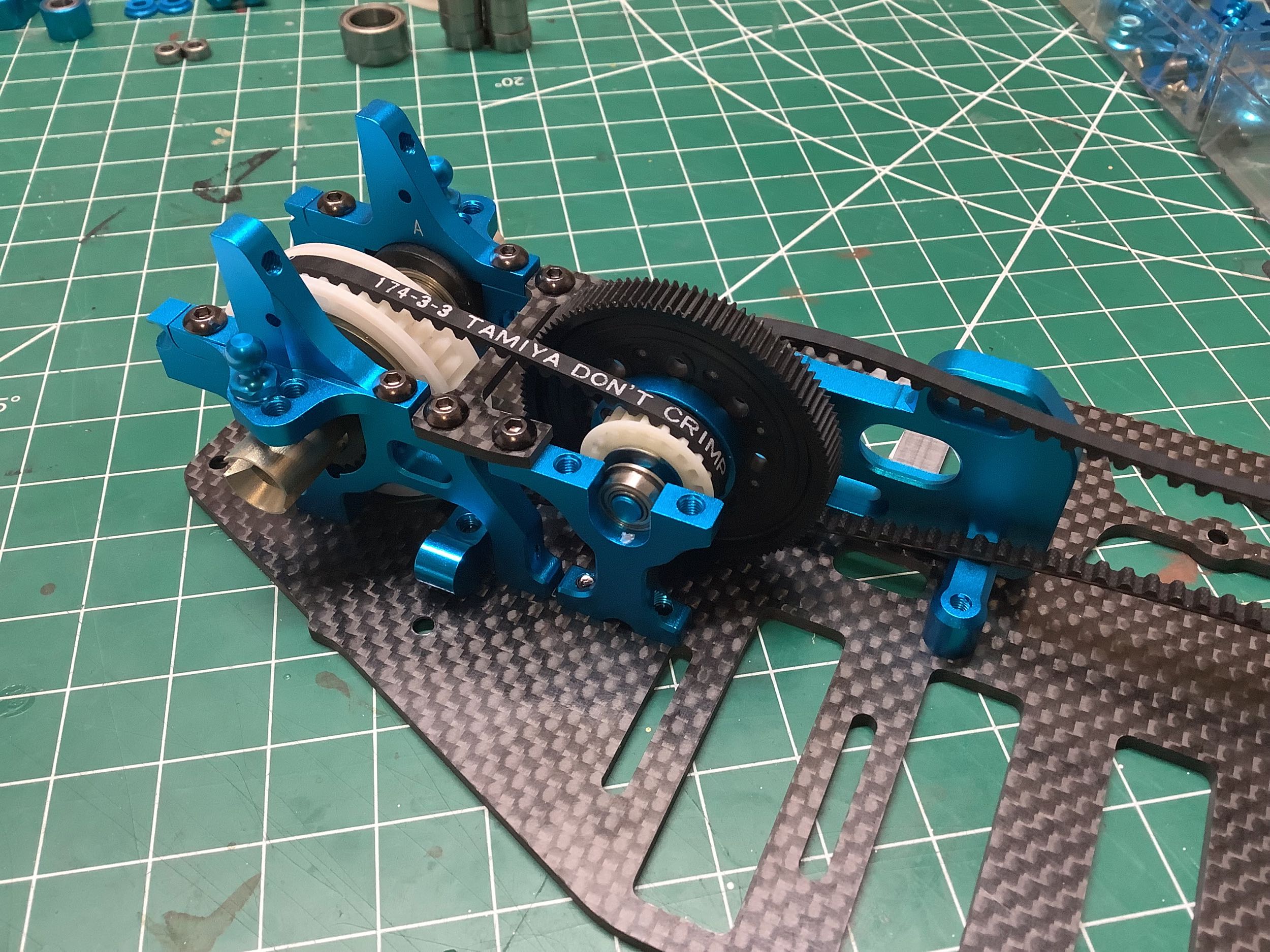
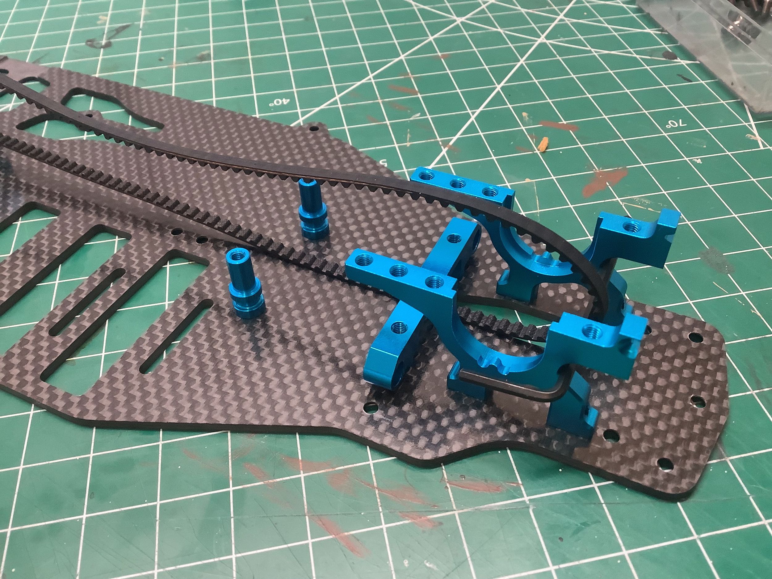
The TRF 416 finally eliminates the front one-way bearing from the center
shaft and instead directly couples both the front and rear pulleys to
the shaft. The pulleys have also been located on either side of
the spur gear instead of both being on one side. The impact of
this is the spur (and also motor) moving slightly toward the center of
the chassis. The spur gear went from 102T to a slightly larger
105T. The carbon upper brace connects the rear bulkheads to the
center bulkheads, but does not capture the bearings for the center
shaft. This means the whole upper chassis brace has to be removed
to access the center shaft.
Time to attach the front bulkheads and steering posts. The
steering posts are much shorter than they were on the TRF 415MSX and the
bulkheads have some additional holes. Otherwise the design and
layout is very similar.
Here you can see the new one piece pulley again. It is the
identical 37T pulley used in the rear except with a bigger central
bore. This time both left and right one-way bearings are
integrated into a single housing instead of being separate parts like on
the TRF 415MSX. The other big change is
that the plastic eccentric bearing housings for belt tension adjustment
now have the scallops integrated into them instead of machining them
into the bulkheads. Both the scallops and the eccentricity are
clearly visible in the photo on the right.
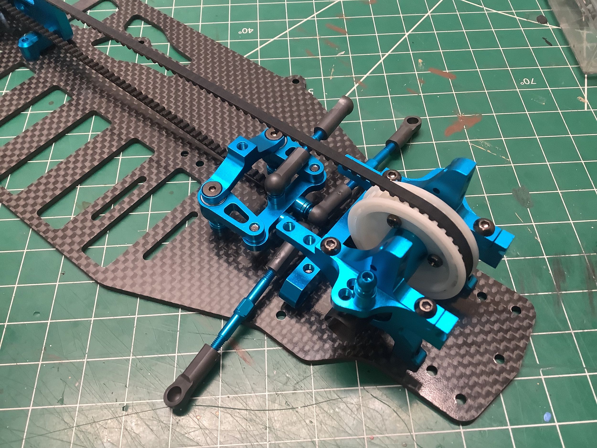
Installing the upper bulkheads captures the front pulley and tightens
the belt. The front steel drive cups are also installed at this
point. If you look at where the belt passes between the steering
posts you can see that it is offset toward the left of chassis.
This is the result of putting the center pulleys on either side on the
spur gear. In the TRF 415MSX, the front pulley was centered.
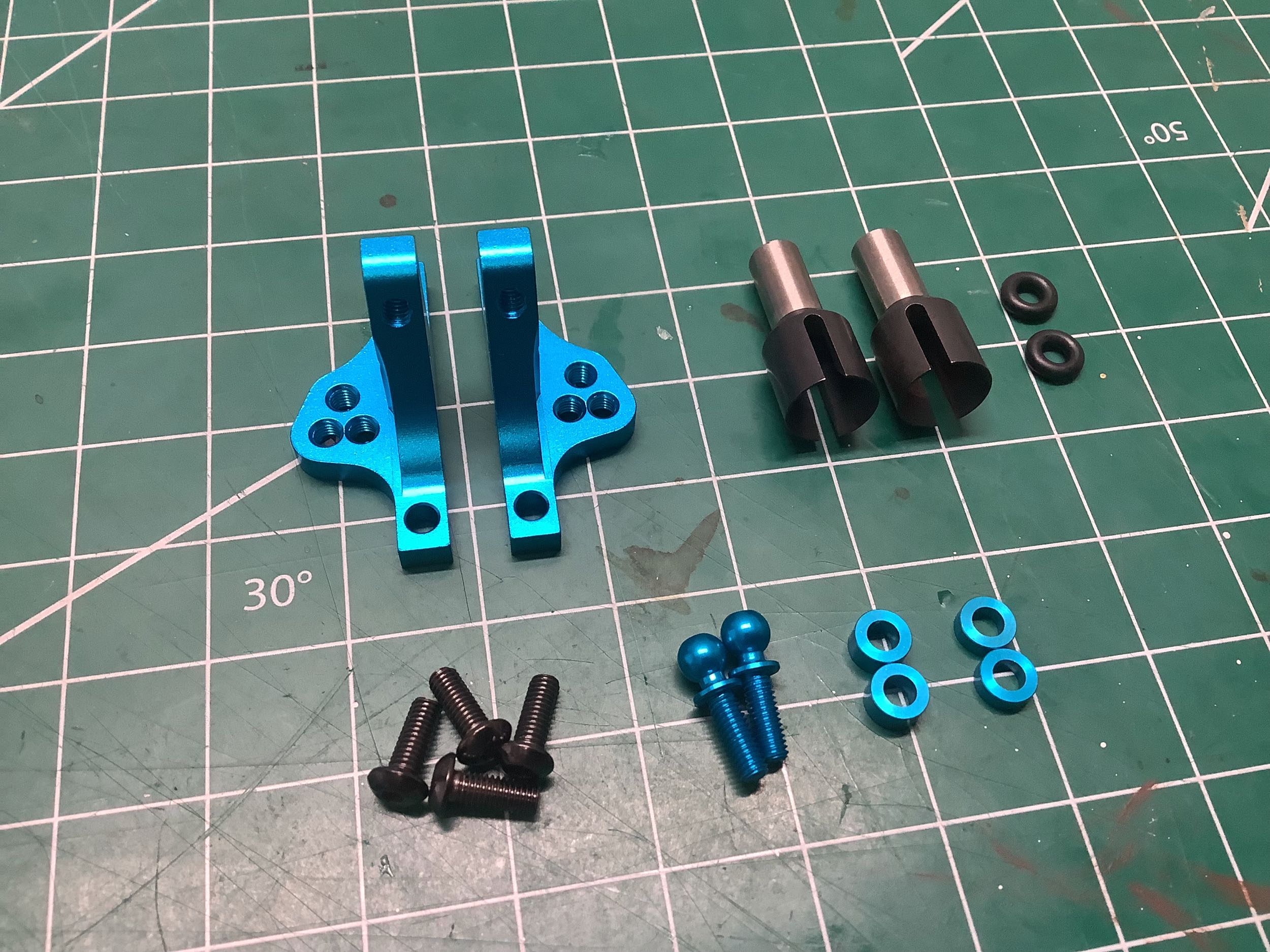
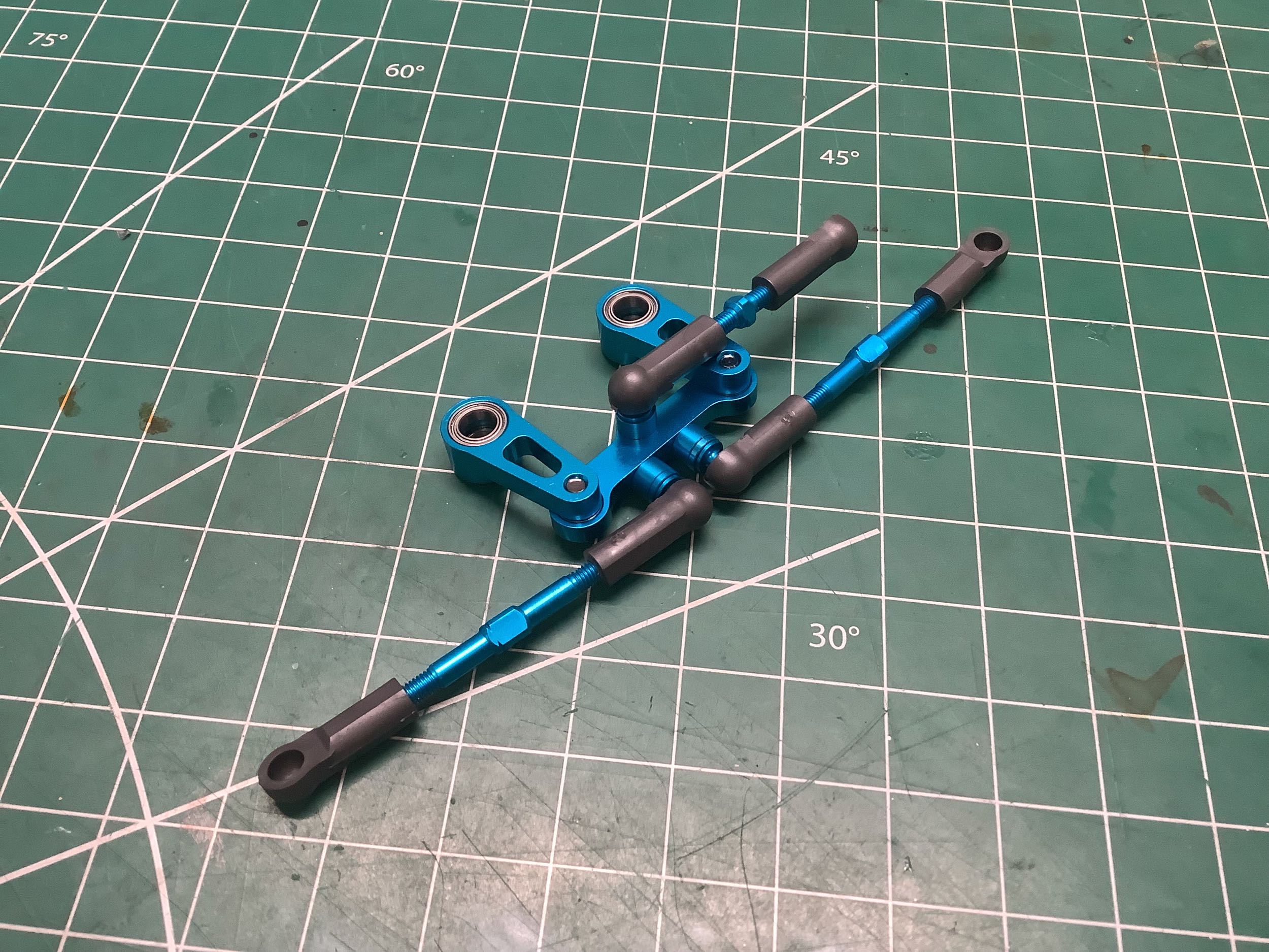
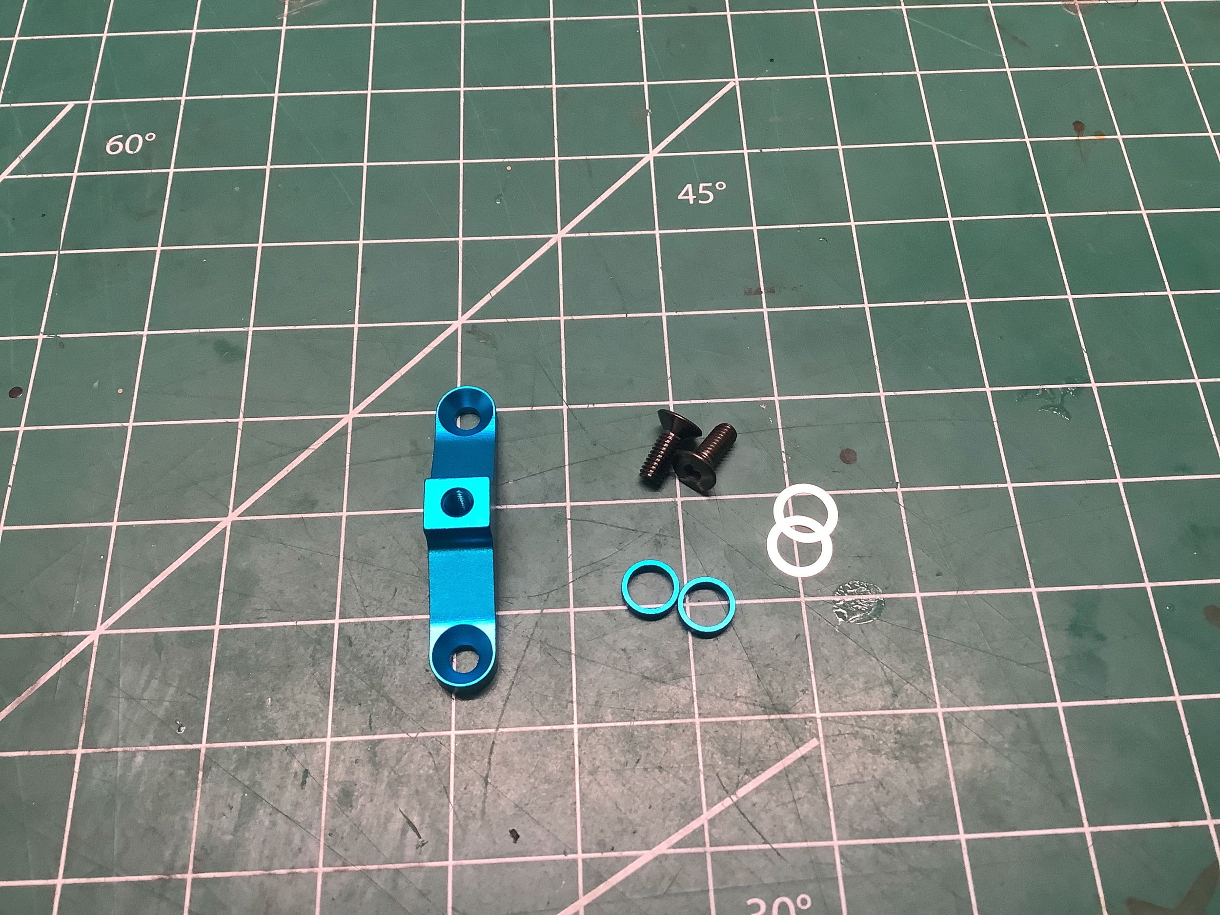
The configuration of these steering cranks is considerably different
than the TRF 415MSX, but very similar to the variation introduced in the
Mark Rheihard edition. Here the servo link is connected to the
steering bridge instead of the right hand crank, the bridge has been
converted from carbon to aluminum, and it has moved under the
cranks. All of this saves a bit of space and puts the mass
slightly lower down. The steering links have also gotten 4.5mm
longer because they attach to the bridge closer to the center of the
chassis.
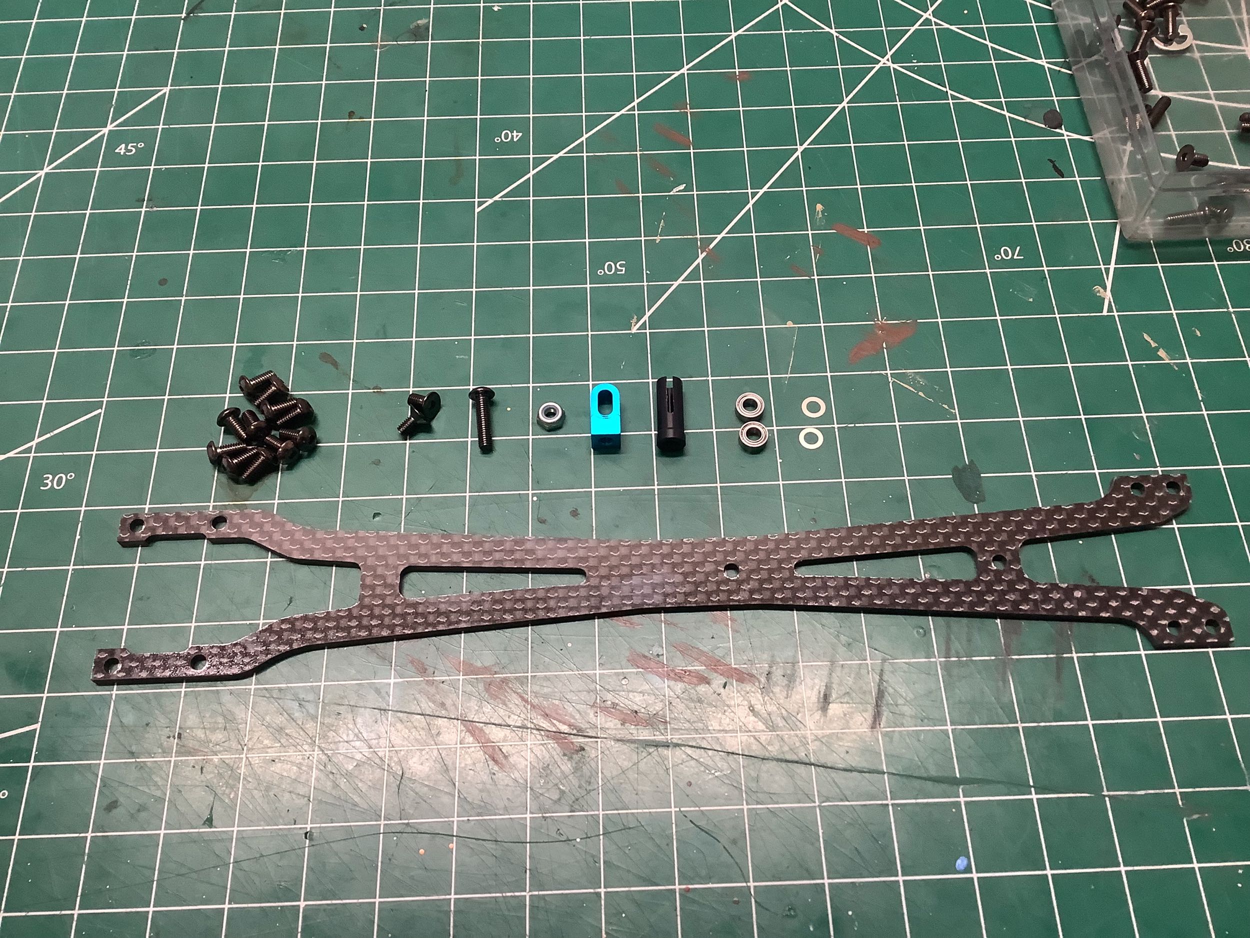
This little steering post support didn't exist on the TRF 415MSX because
the steering posts connected directly to the upper chassis brace.
This provides a bit of additional lateral support to the top of the
posts.
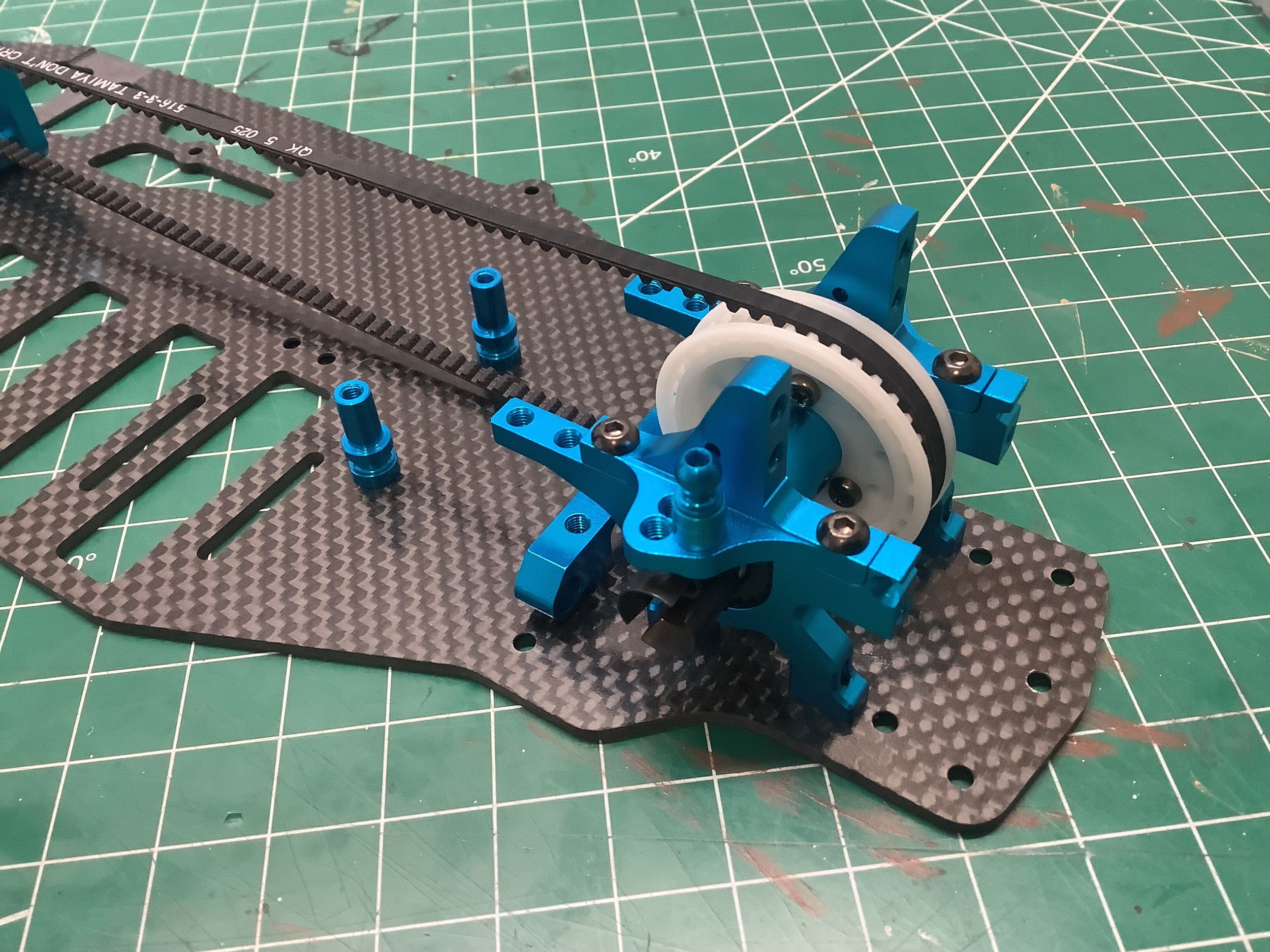
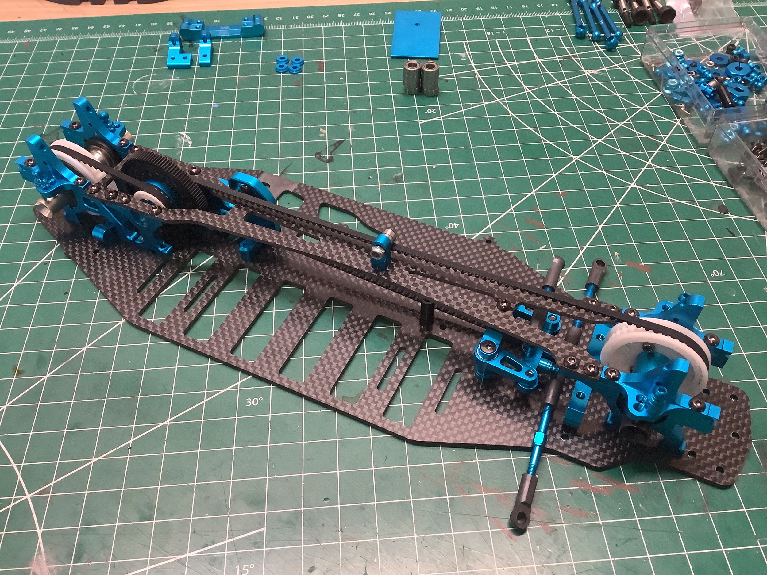
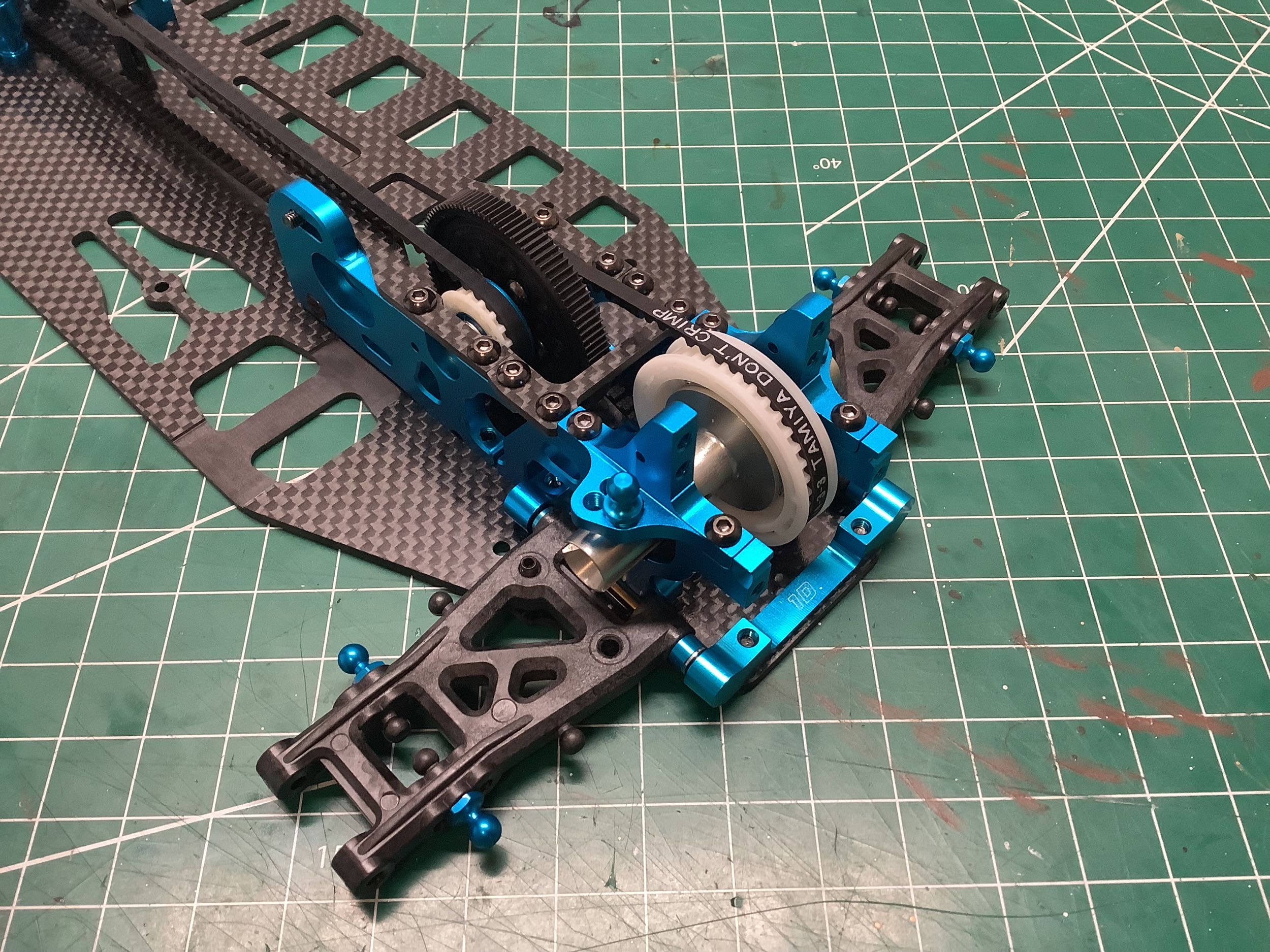
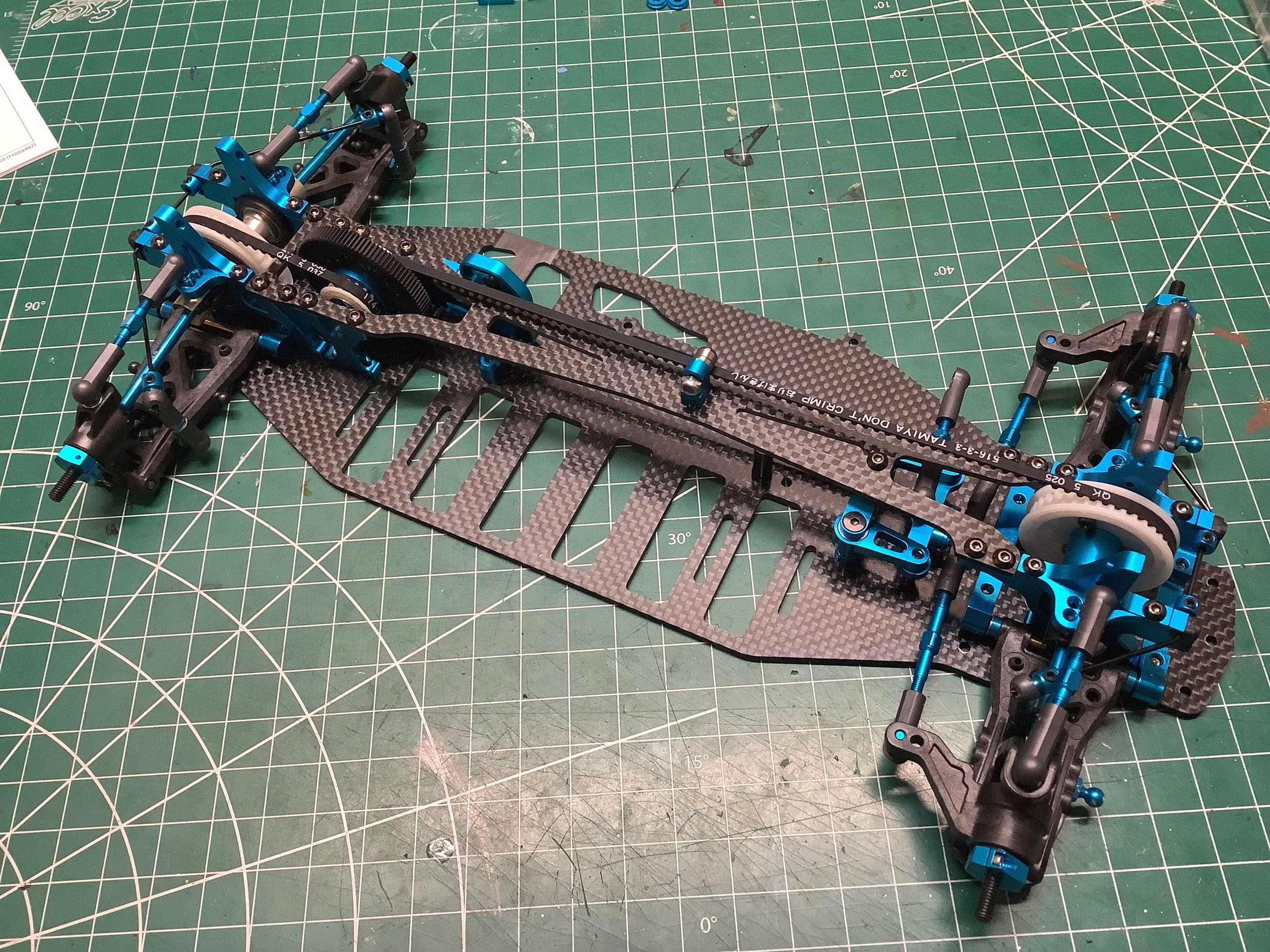
The upper chassis brace is installed much earlier in the build than on
the TRF 415MSX, and is also much longer (roughly 17cm instead of 11.5cm)
because it now stretches all the way from the front to the rear
bulkheads. That little bearing in the middle is a belt support to
keep that long belt from slapping.
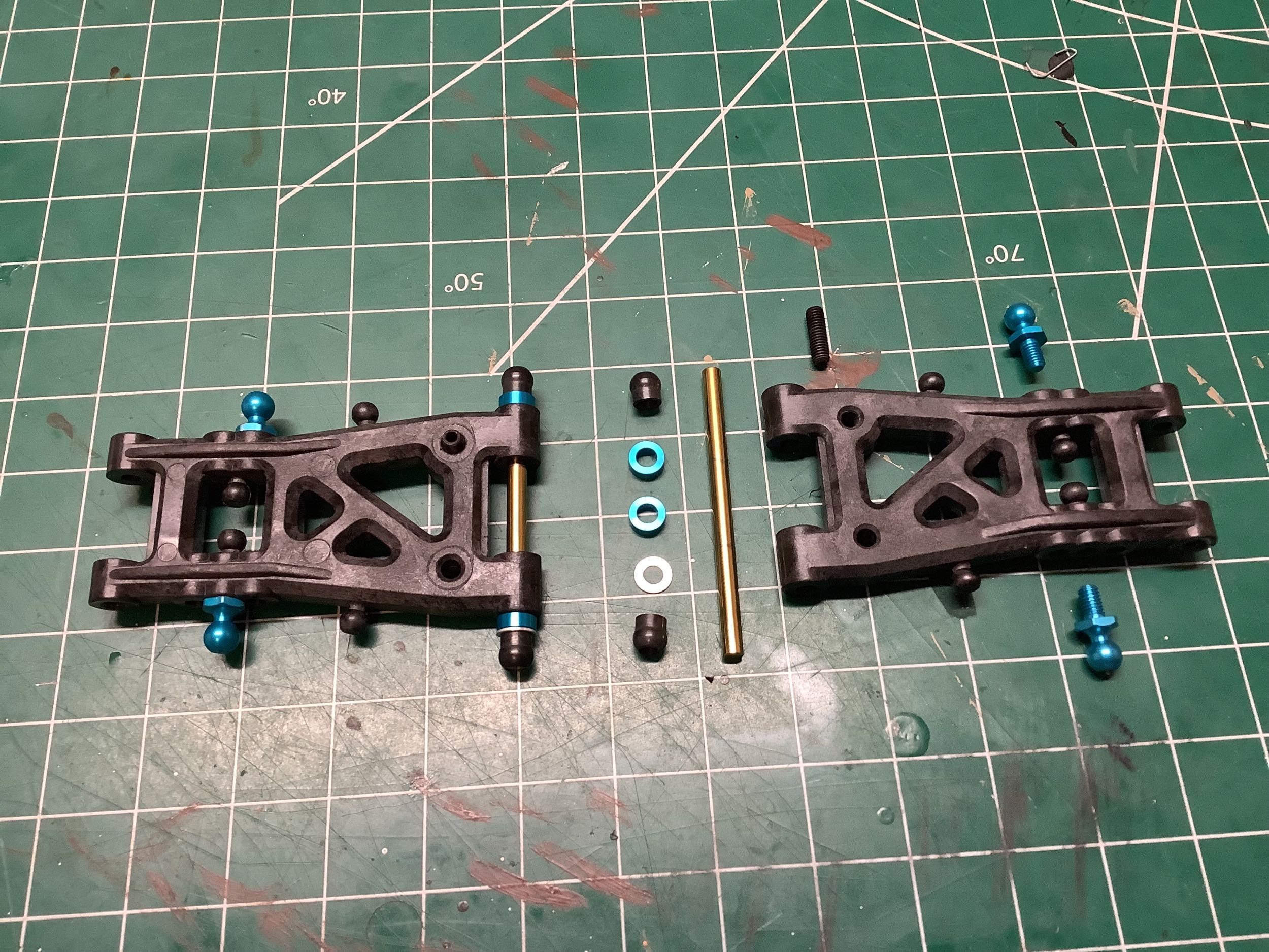
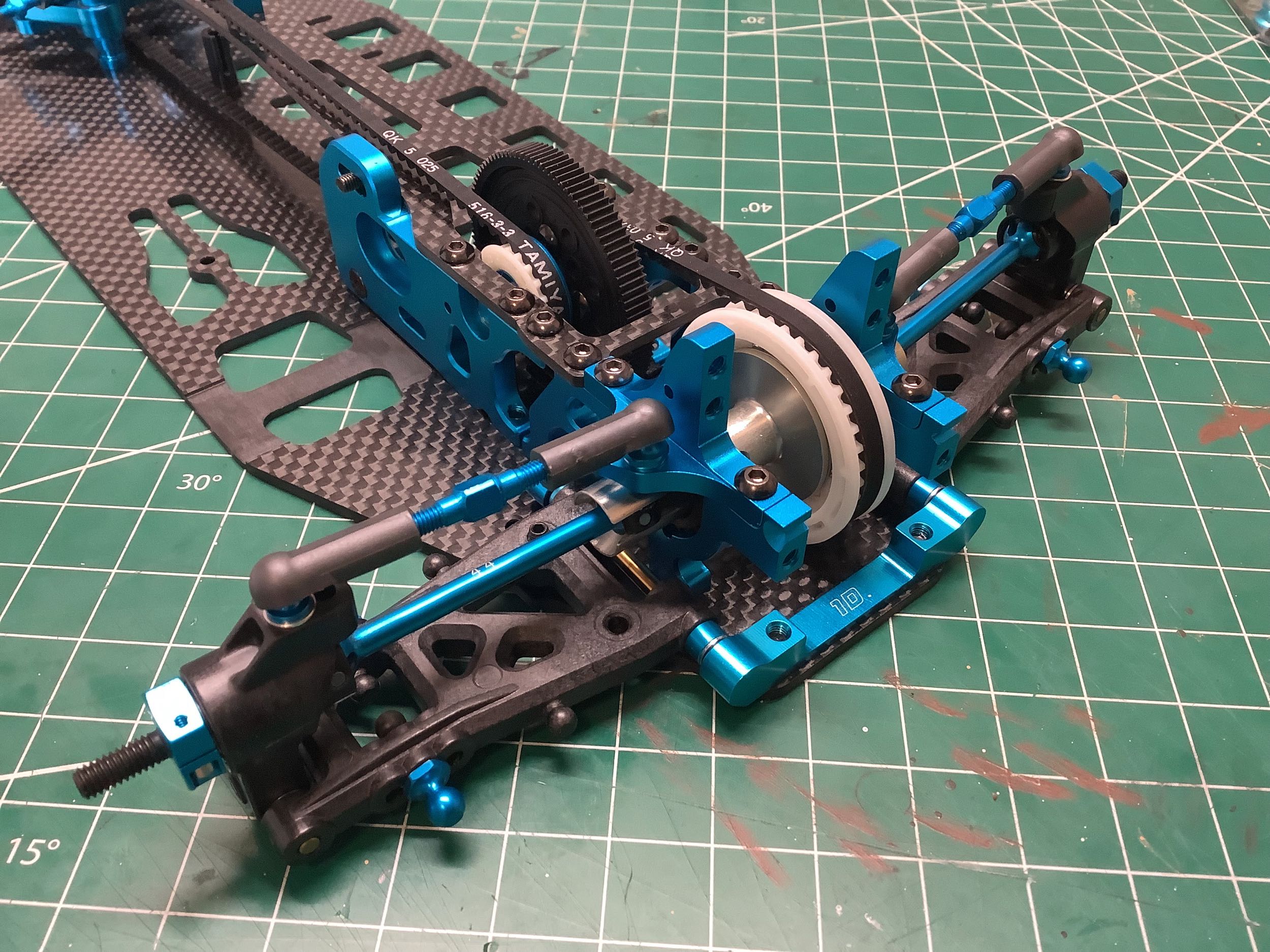
The rear suspension arm assembly is nearly identical to that of the TRF
415MSX with the only difference being the configuration of the
spacers. The default rear toe is still 3 but now using 1XB and 1D
suspension mounts instead of 1XD and 1B. This would theoretically
result in a 1.5mm wider track width, but I think that is probably
cancelled out by the new uprights.
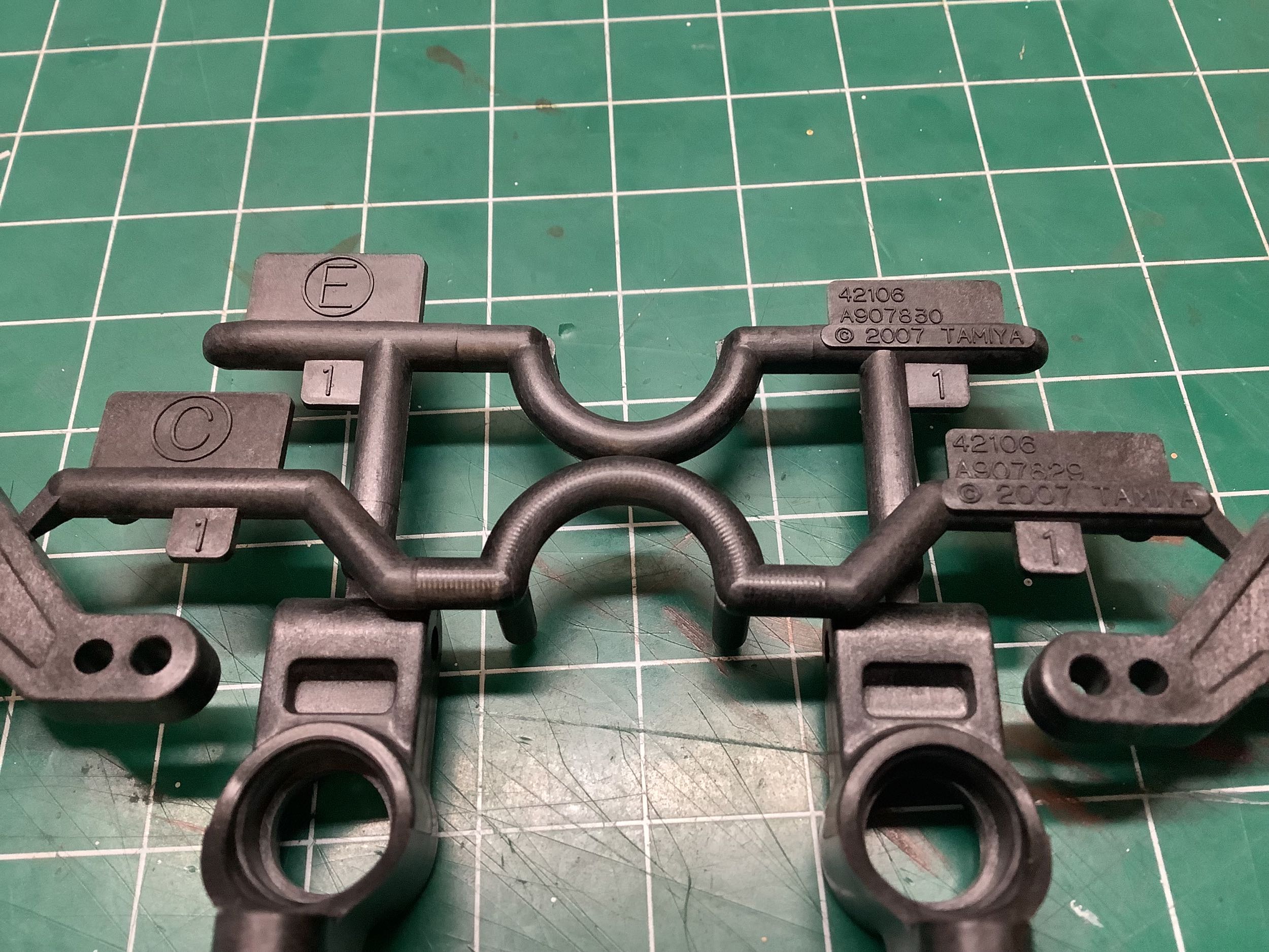
Speaking of new rear uprights, you can see here that the E tree for the
uprights and the C tree for the steering knuckles are both stamped with
42106 indicating that they are new for the TRF 416. These both use
fiber reinforced plastic.
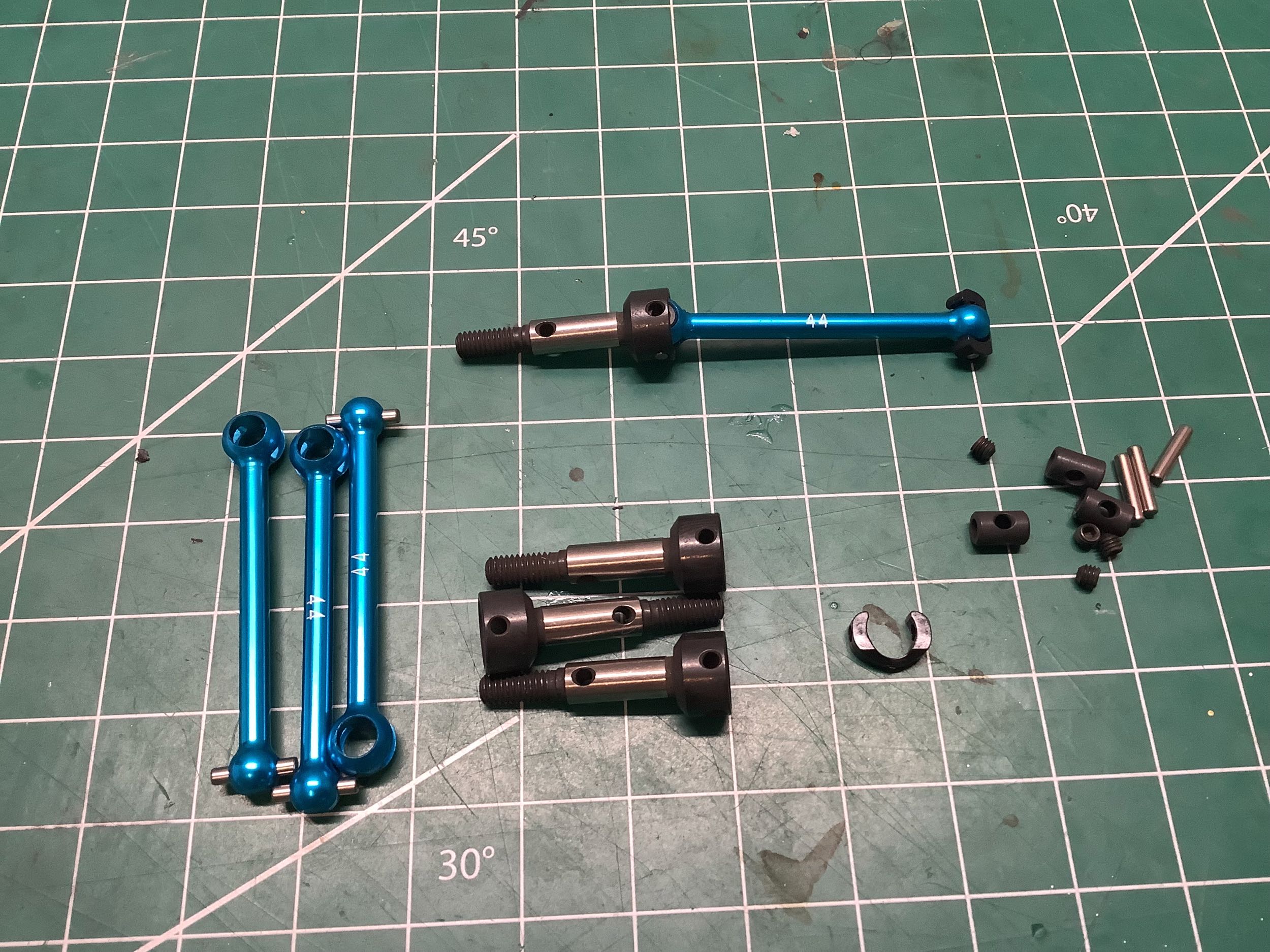
These lovely CVD style aluminum axles are nearly the same as those from
the TRF 415MSX, but they are 2mm shorter and the steel wheel axles are
slightly different. The picture on the right shows how they are
installed into the new plastic uprights. The same clamping 12mm
hexes are used.
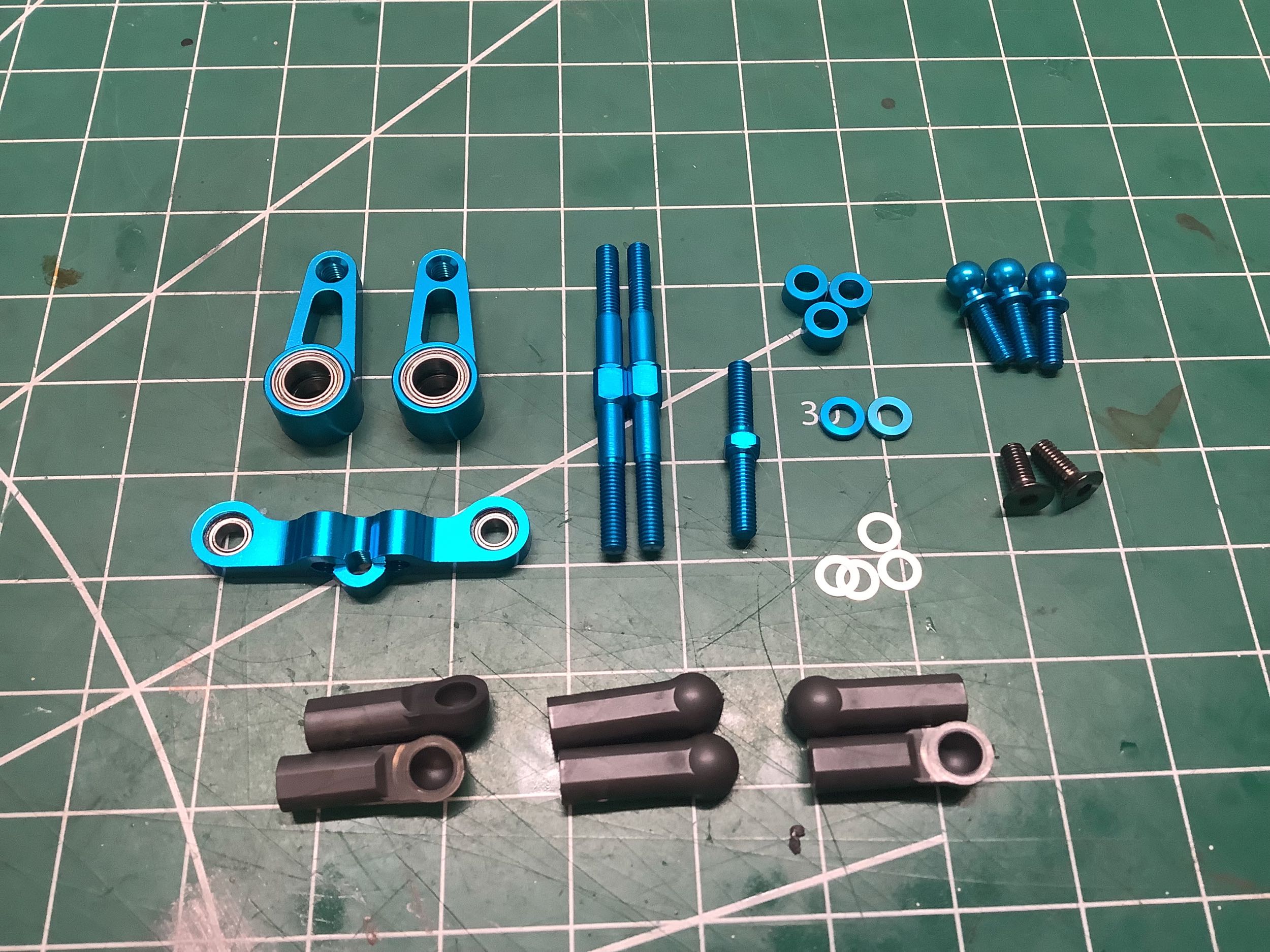
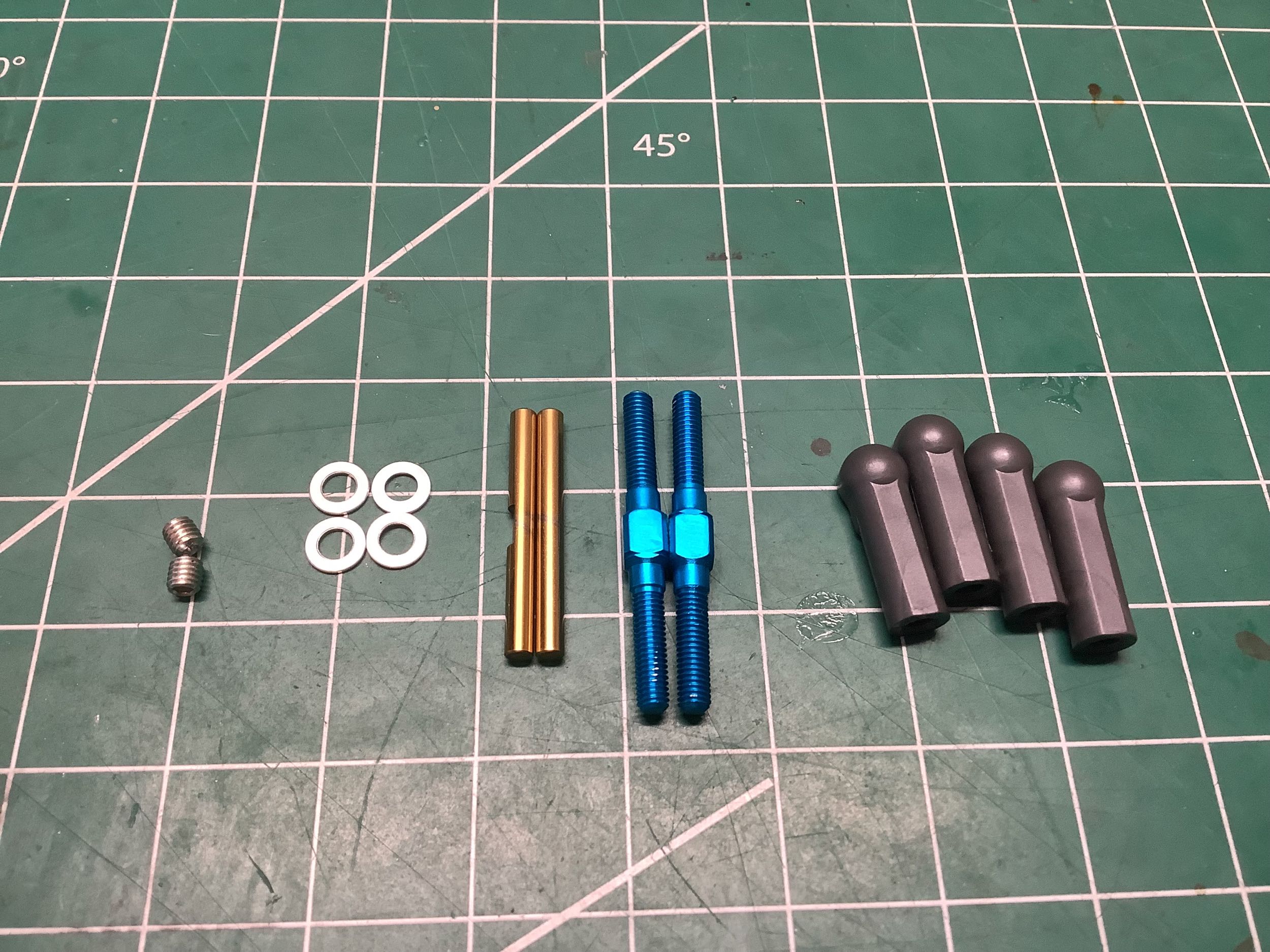
Now we'll install the rear suspension using the turnbuckles and hinge
pins shown. This works just like the TRF 415MSX except for the
specific adjusted length of the turnbuckles (the actual 3x32mm parts are
the same).
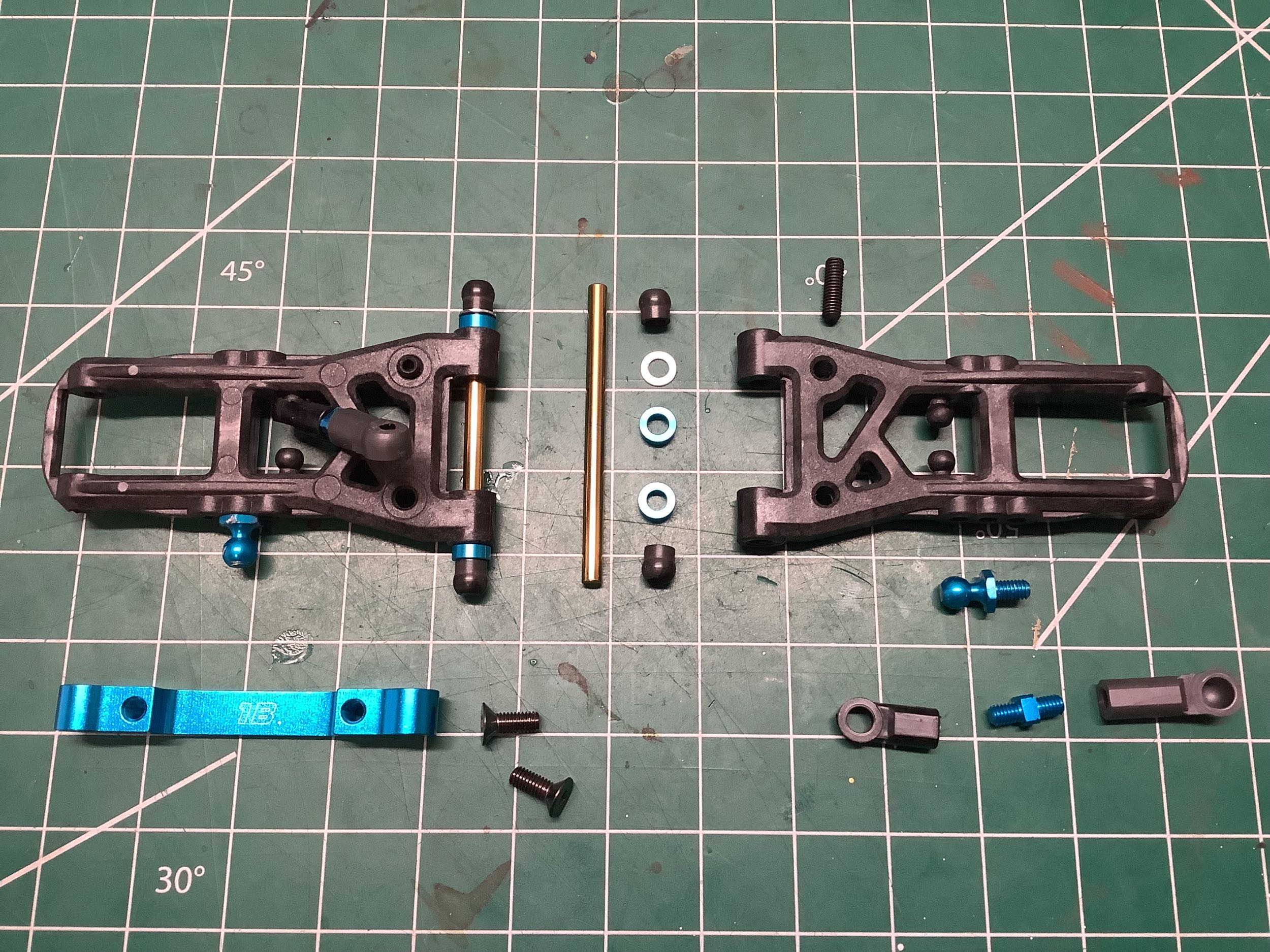
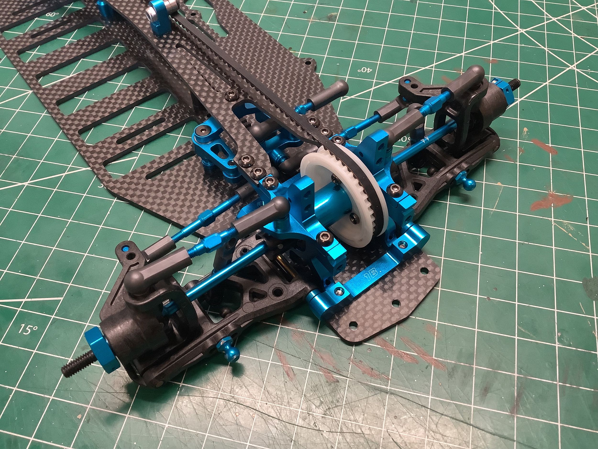
Now we can start the subassembly steps for the front suspension.
The parts and assembly method are all carried forward from the TRF
415MSX including the position of the shock balls and sway bar
links. Even the same (1B) front suspension mount is used.
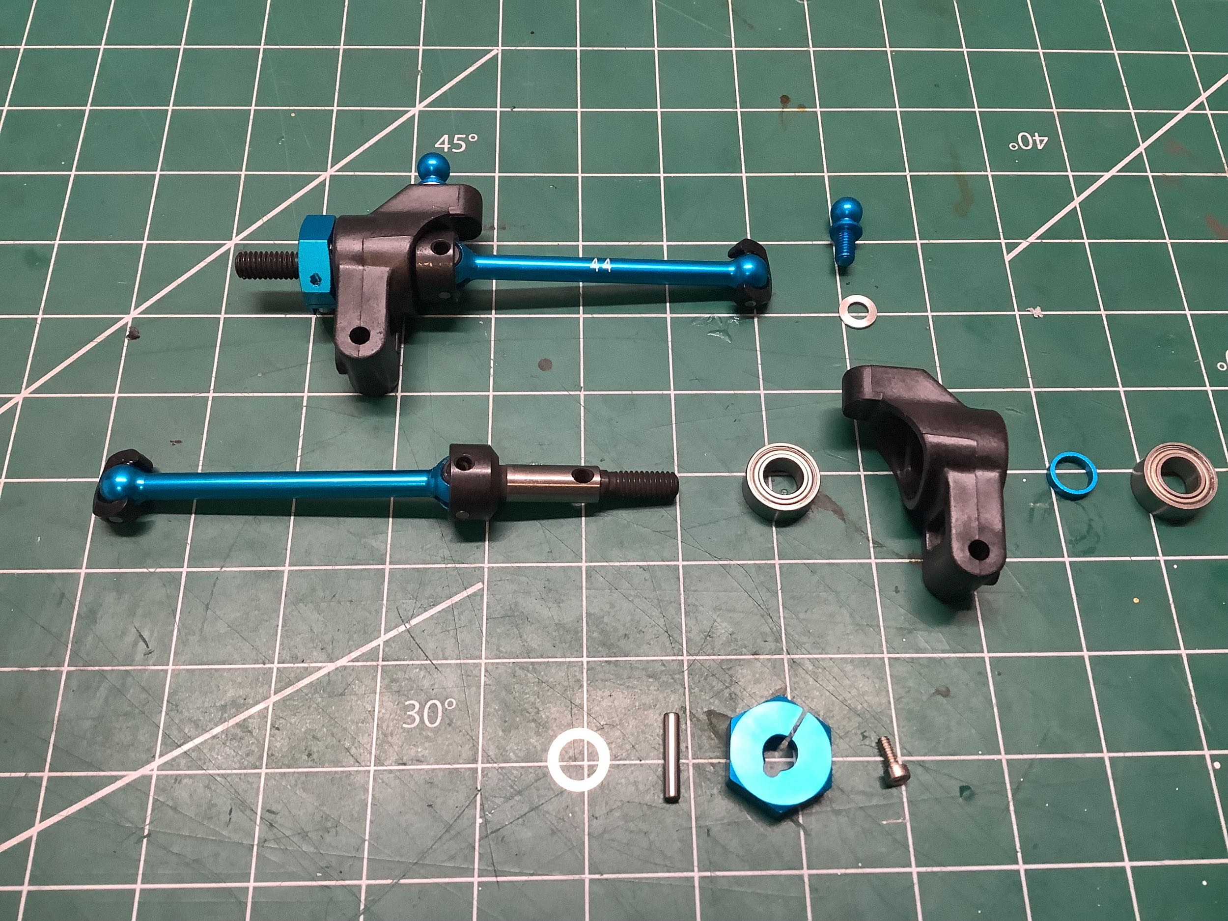
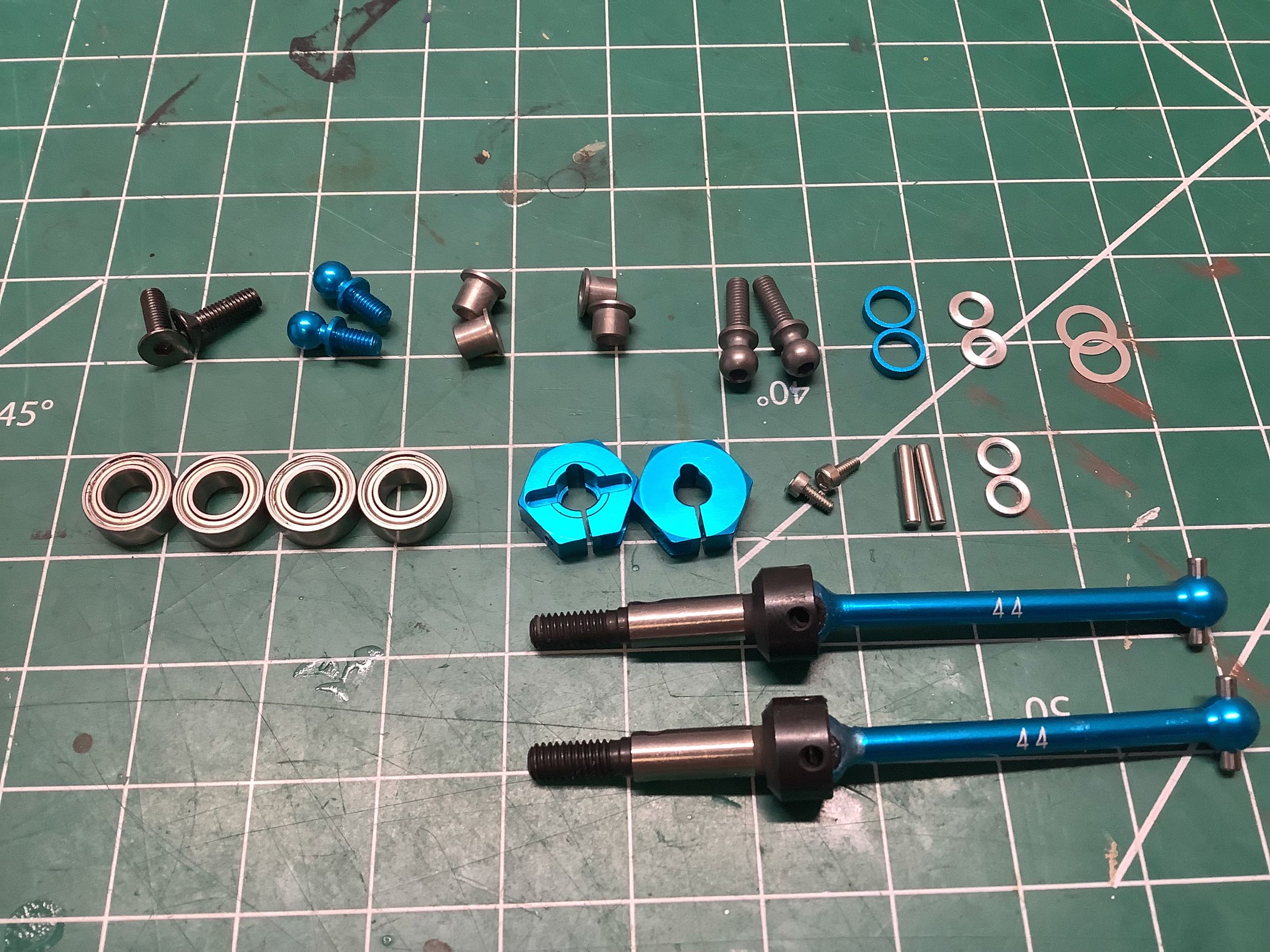
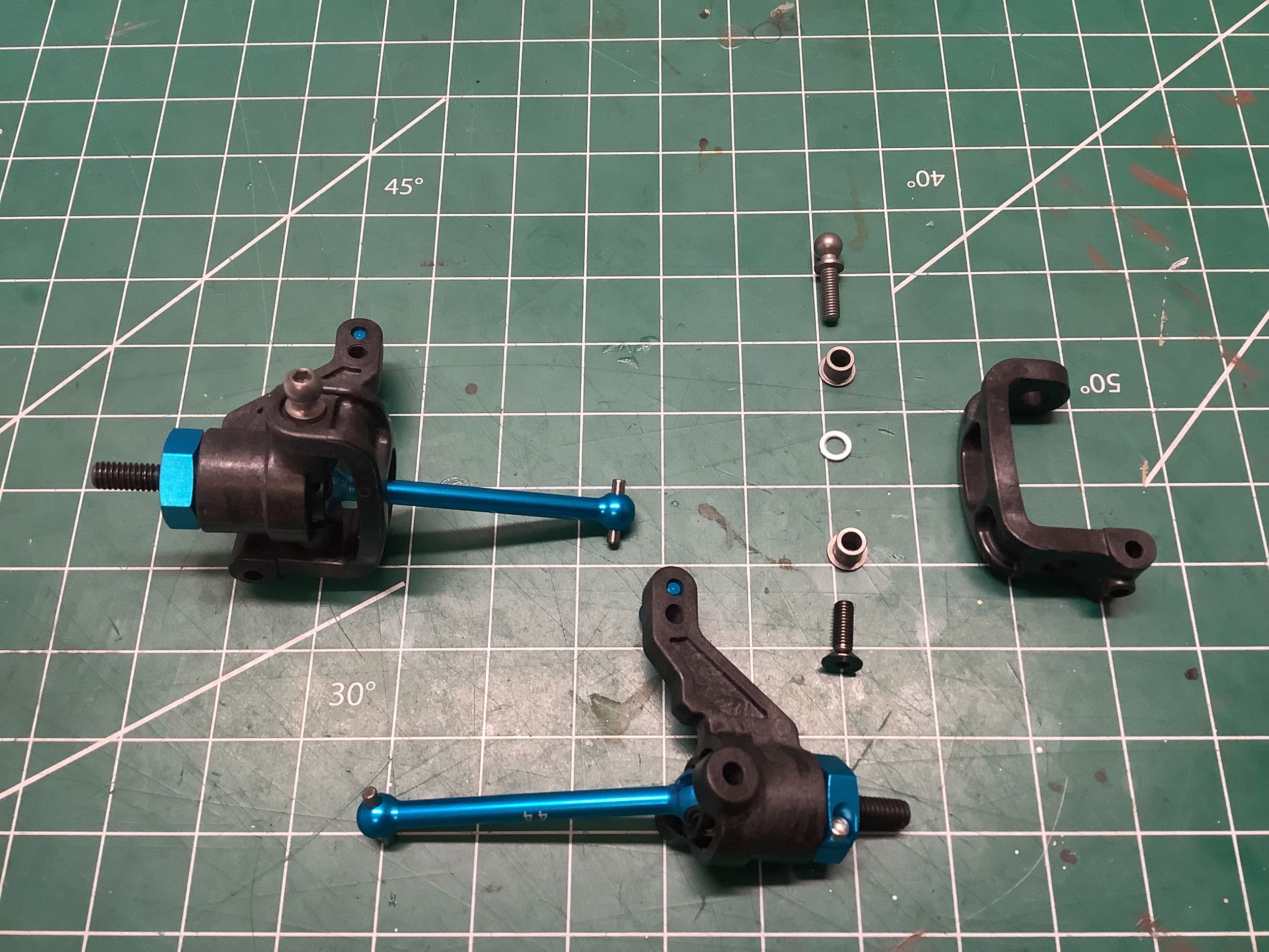
Here are the parts for the front axles and steering knuckles.
Compared to the TRF 415MSX, the axle length has reduced from 46mm to
44mm. While the steering knuckles still come from the C parts
tree, they have actually changed slightly. The new parts use 10x5mm bearings instead of 9x5mm.
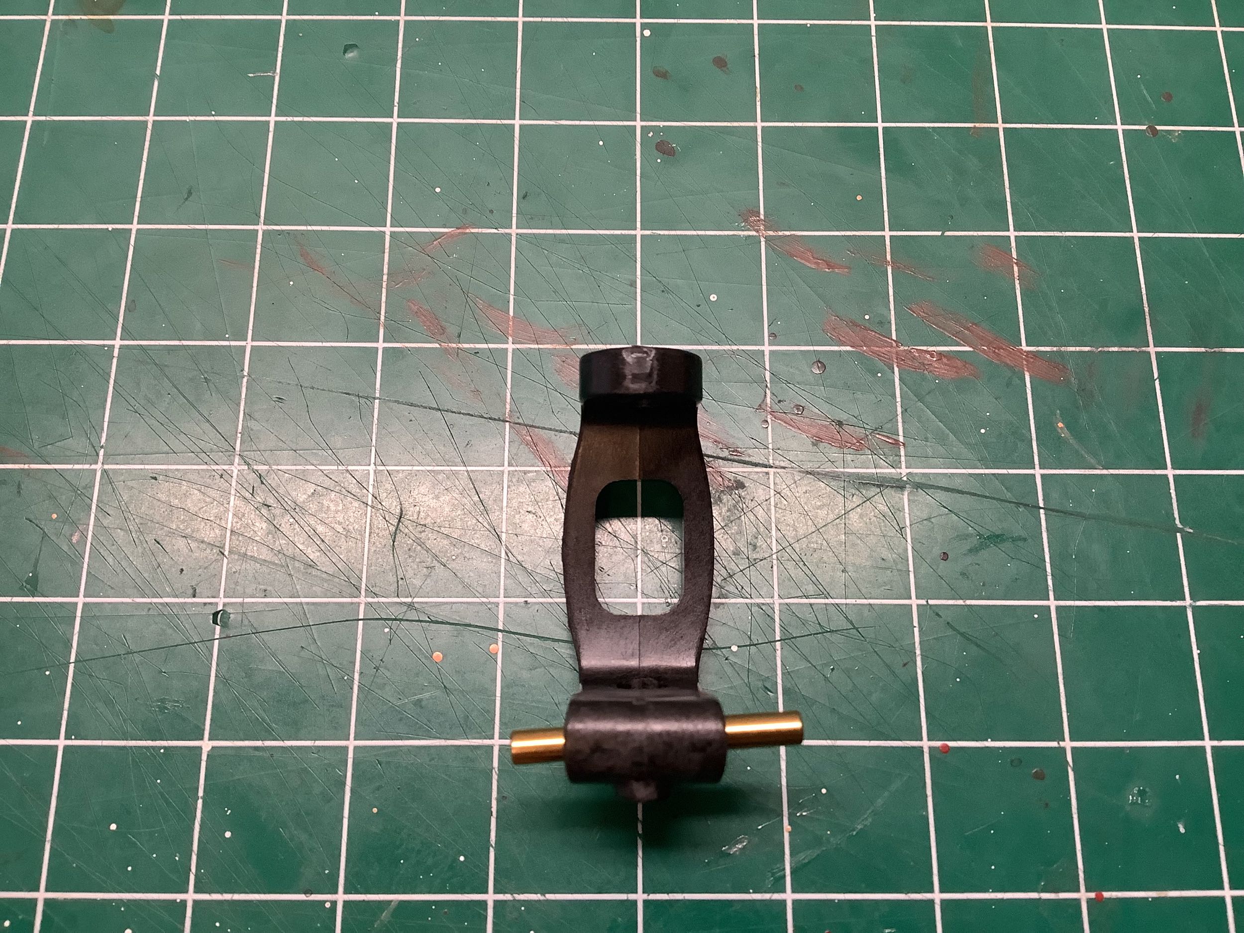
The picture on the left shows one of the hub carriers (F-parts).
You can see the 4 degree camber angle built into the hub by looking at
the angle the hinge pin forms with rest of the part. The TRF
415MSX came with two sets of carriers (2° and 4°) originally from the TA
Evo IV chassis. The TRF 416 has a similar but new set of hubs
from the TA-05 IFS, this time with only the 4° option. It's not
entirely clear why they chose to change the hubs even though the
suspension arms are exactly the same, but the new parts seem to have
more structural reinforcement and are also made from carbon filled
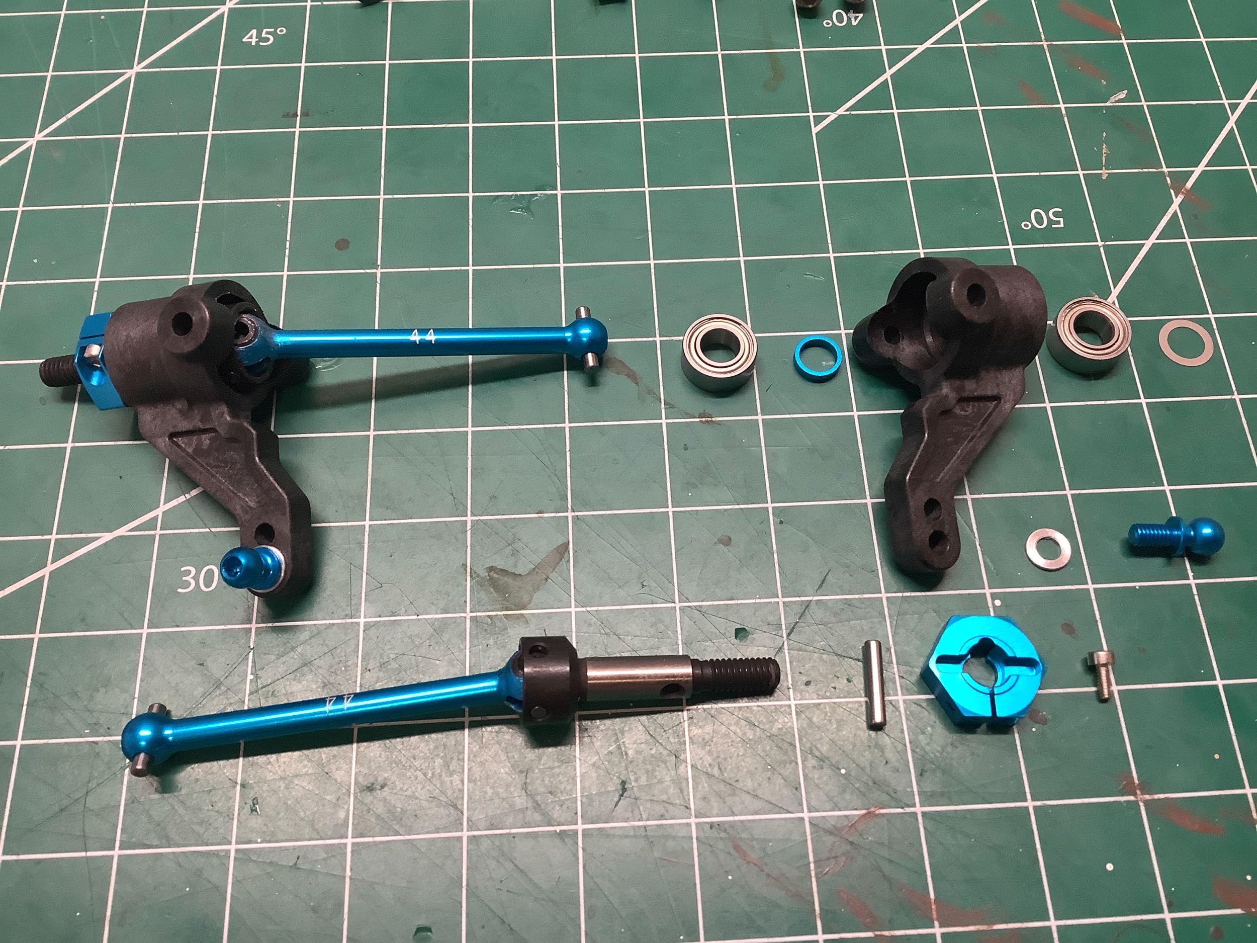
plastic. The new steering knuckles (C-parts) are not from
the TA-05 IFS. The new assembly method is actually a bit tricky
for two reasons. Firstly, the bushings install into the hubs from
the inside instead of the outside which makes them difficult to hold in
place while the knuckle is inserted. Secondly, the upper and lower
bushing are very slightly different (4.5x3.5mm vs. 4.6x4.7mm) which
makes it easy to install them wrong. I can't imagine why it was
necessary to make them 0.1mm different in diameter.
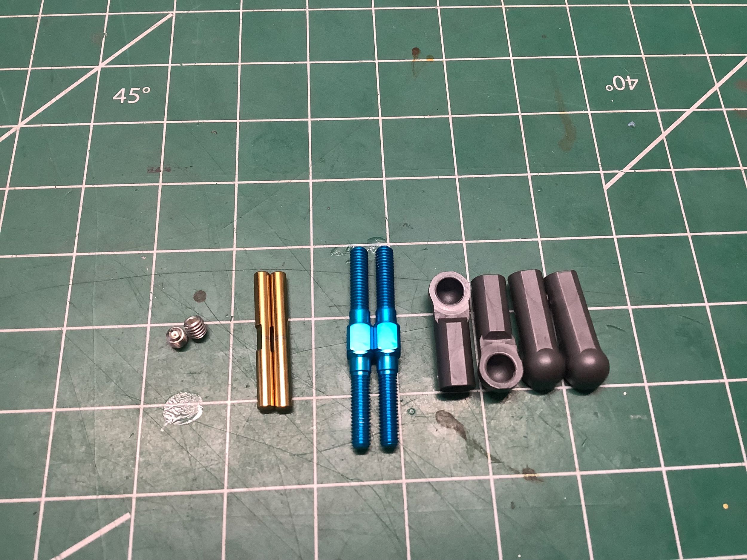
There's nothing special about the front camber links. They go
together just like the rear versions and are the same length as those
used on the TRF 415MSX. In fact it takes careful observation to
tell the difference between the completed front suspension assemblies of
these two chassis.
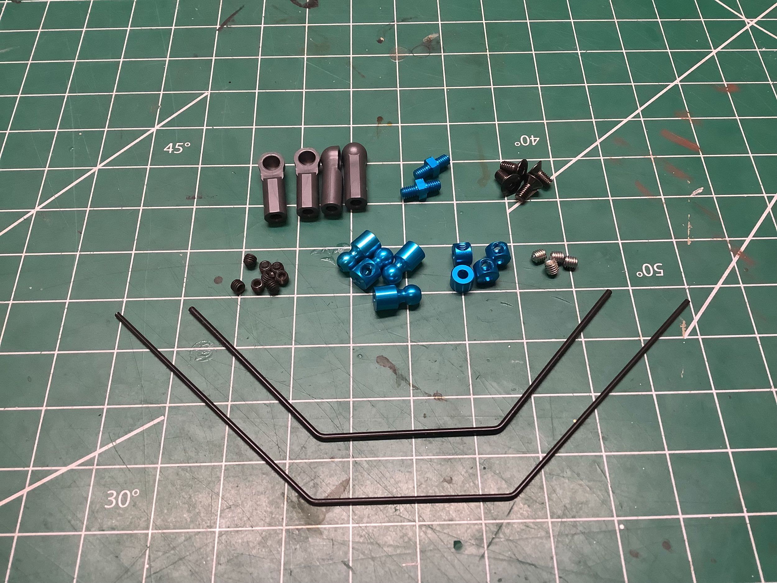
The TRF 416 is the first model to introduce set screws on the brackets
which support the anti-sway bars. These allow the builder to
adjust the clearance and make sure they fit very snugly and transmit
torque efficiently. The TRF 415MSX used color coded sway bars to
indicate stiffness (yellow and red), but on the 416 they are both
black. The front bar is stiffer (larger diameter) than the
rear.
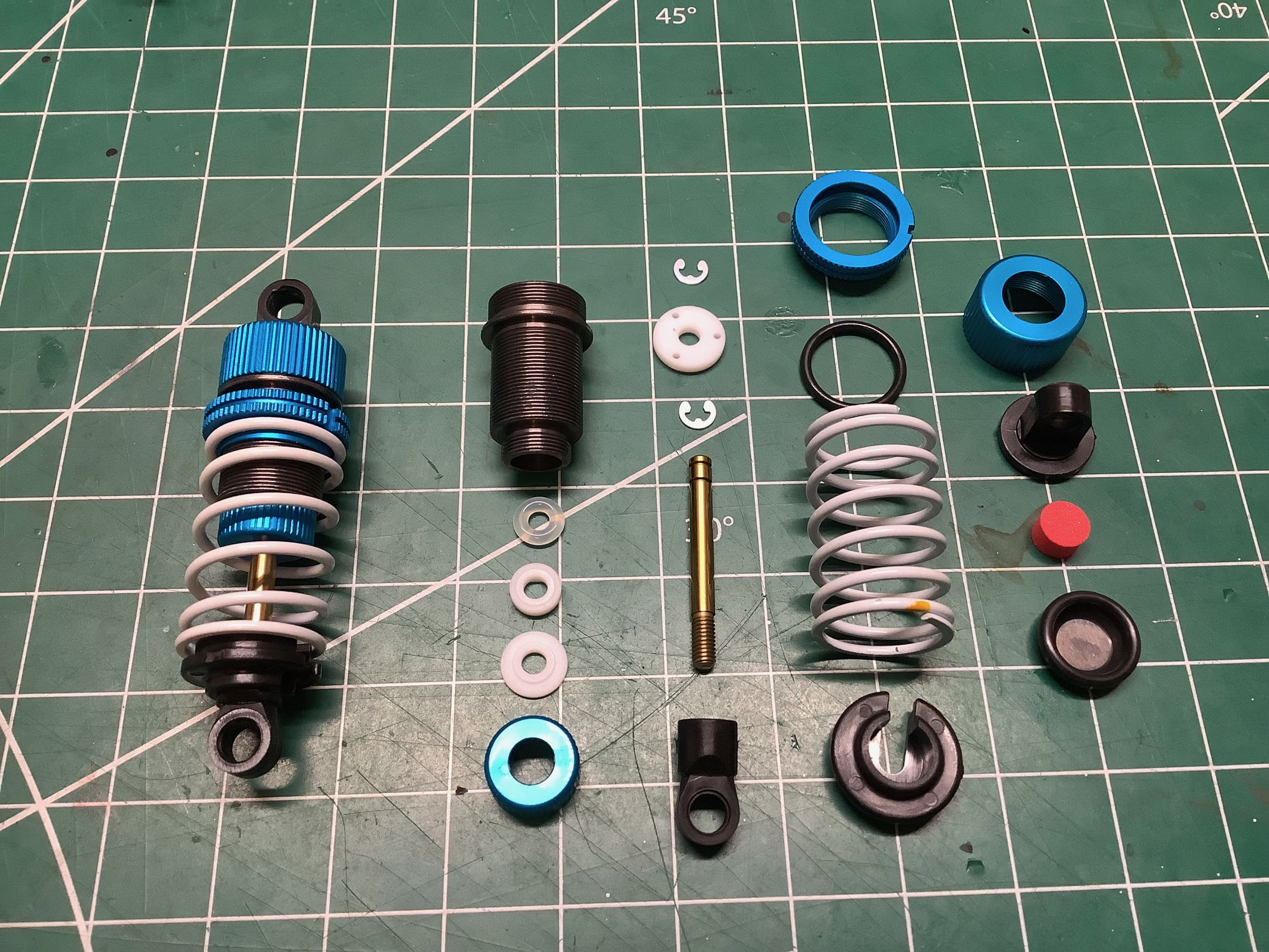
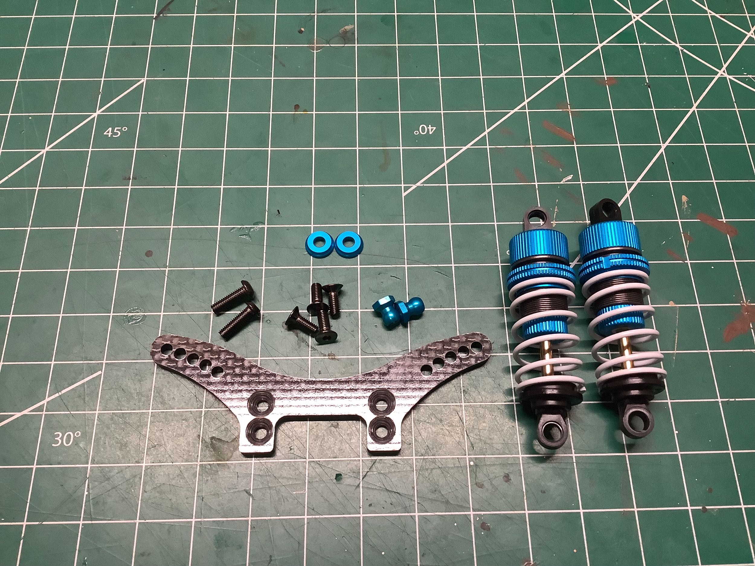
Time to assemble the beautiful TRF shocks. I can't find any
obvious difference between these shock bodies and those used on the TRF
415MSX, but they are not the same part number. I think perhaps the
415MSX parts had the High Lubrication (HL) coating but these do
not). The 416 also uses different stiffness front (hard, blue
band) and rear (medium, yellow band) springs.
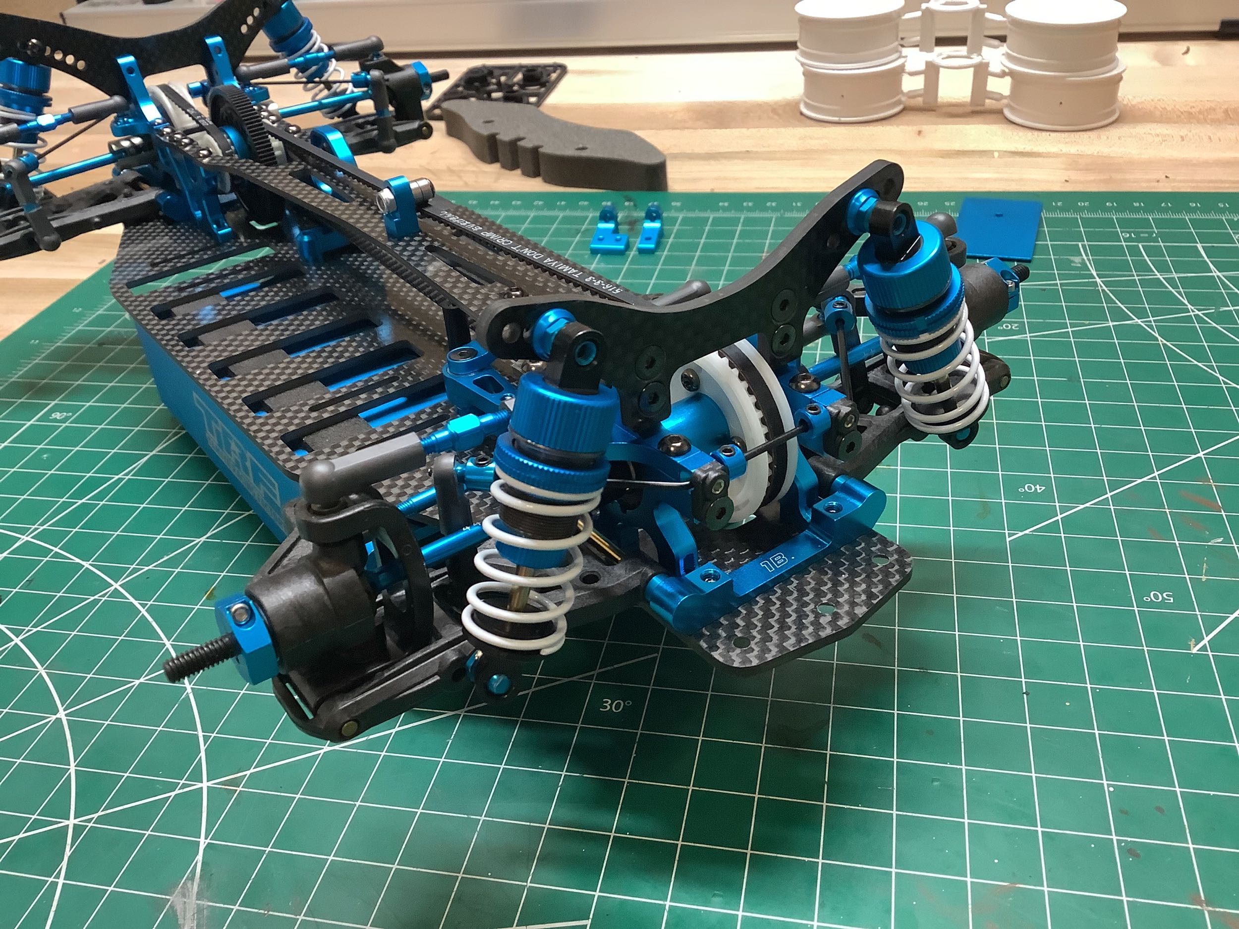
They seem to change the shock tower geometry with pretty much every
version of the TRF chassis, and this is no exception. They are
almost the same as those on the TRF 415MSX, but not quite. The
geometry appears nearly the same, but this new version has countersunk
holes for flush mount screws. Why use a common part when you can
make them different?
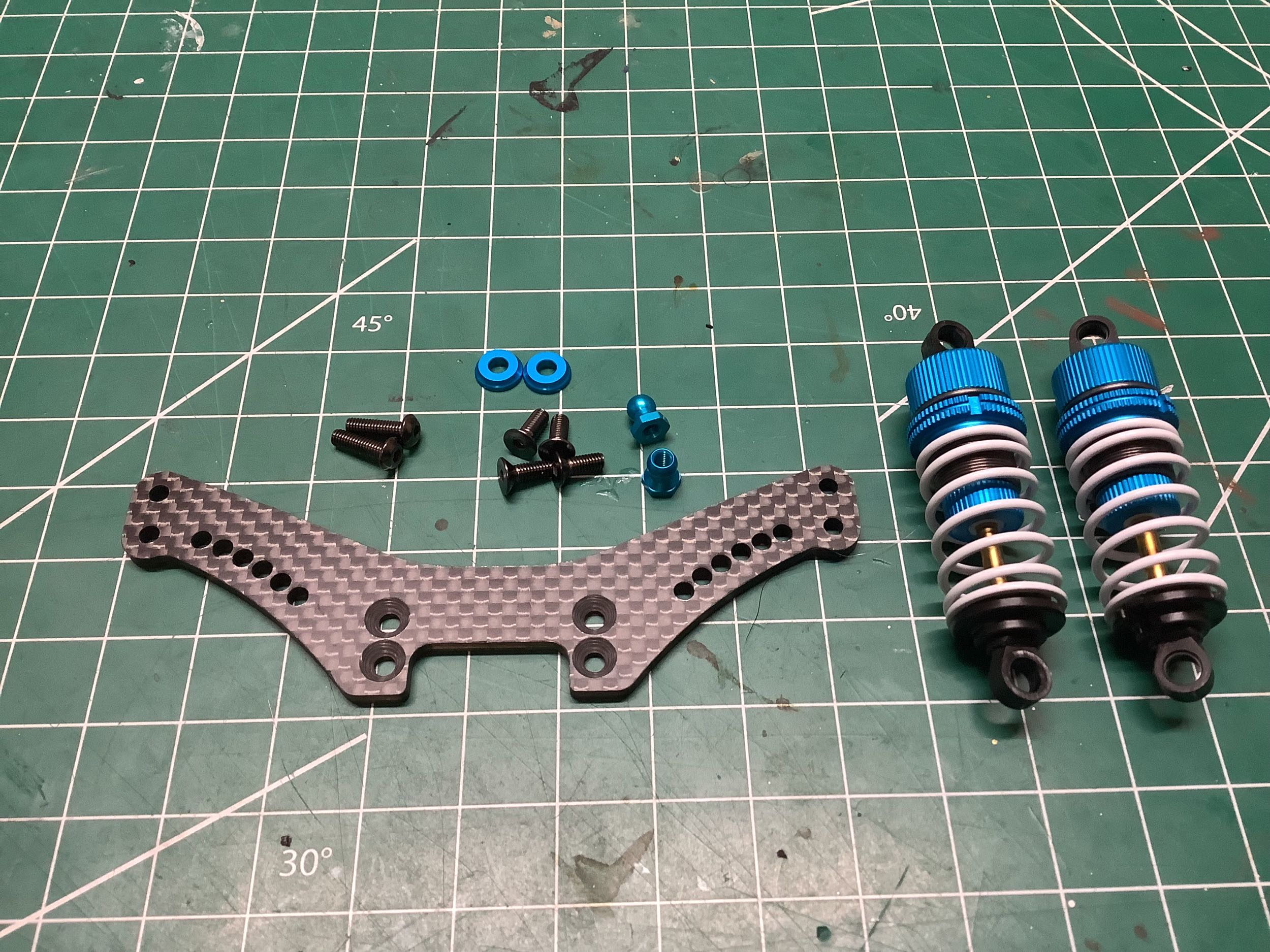
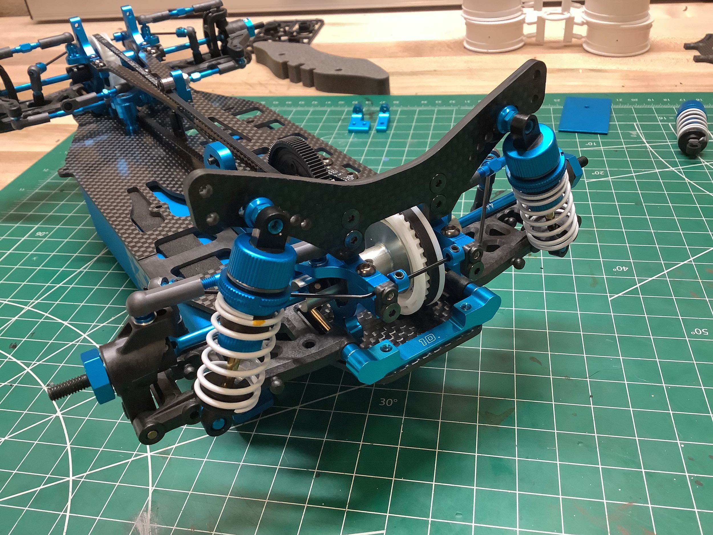
The story is much the same in the front. This shock tower is new
for this model, but looks extremely similar to what we've seen
before. The white springs at least make it easily distinguished
from the yellow used on the TRF 415MSX.
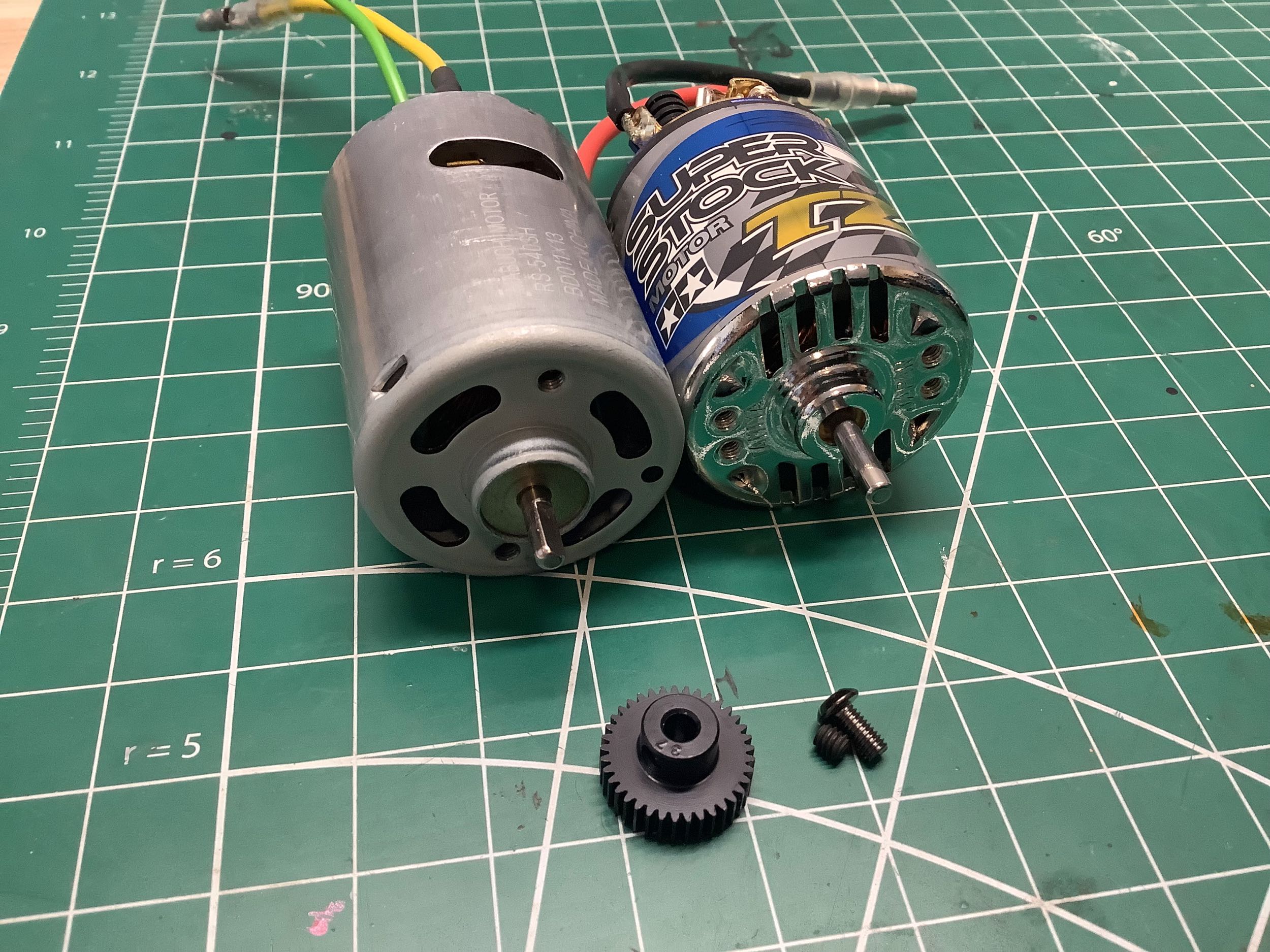
I've been putting silver can motors in my other TRF chassis intended
just for display, but the TRF 416 is the first in which I found that to
be impossible. The front bearing journal on the silver can is too
large in diameter to fit into the slot on the motor mount, so this motor
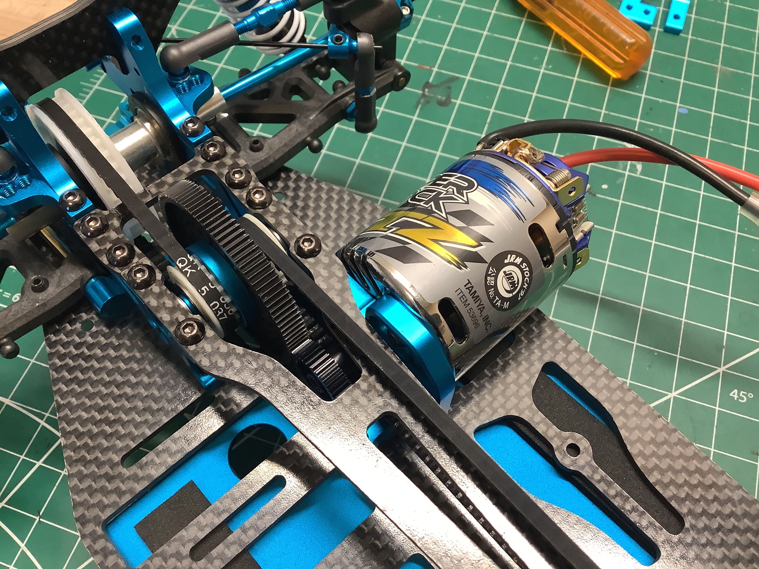
cannot be installed. I used a Super Stock TZ motor instead which
looks much better anyway. In fact, it looks so much better that I
may go back and change out the motors on the previous models. RC
collectors are experts in spending money on upgrades that offer no
actual improvement.
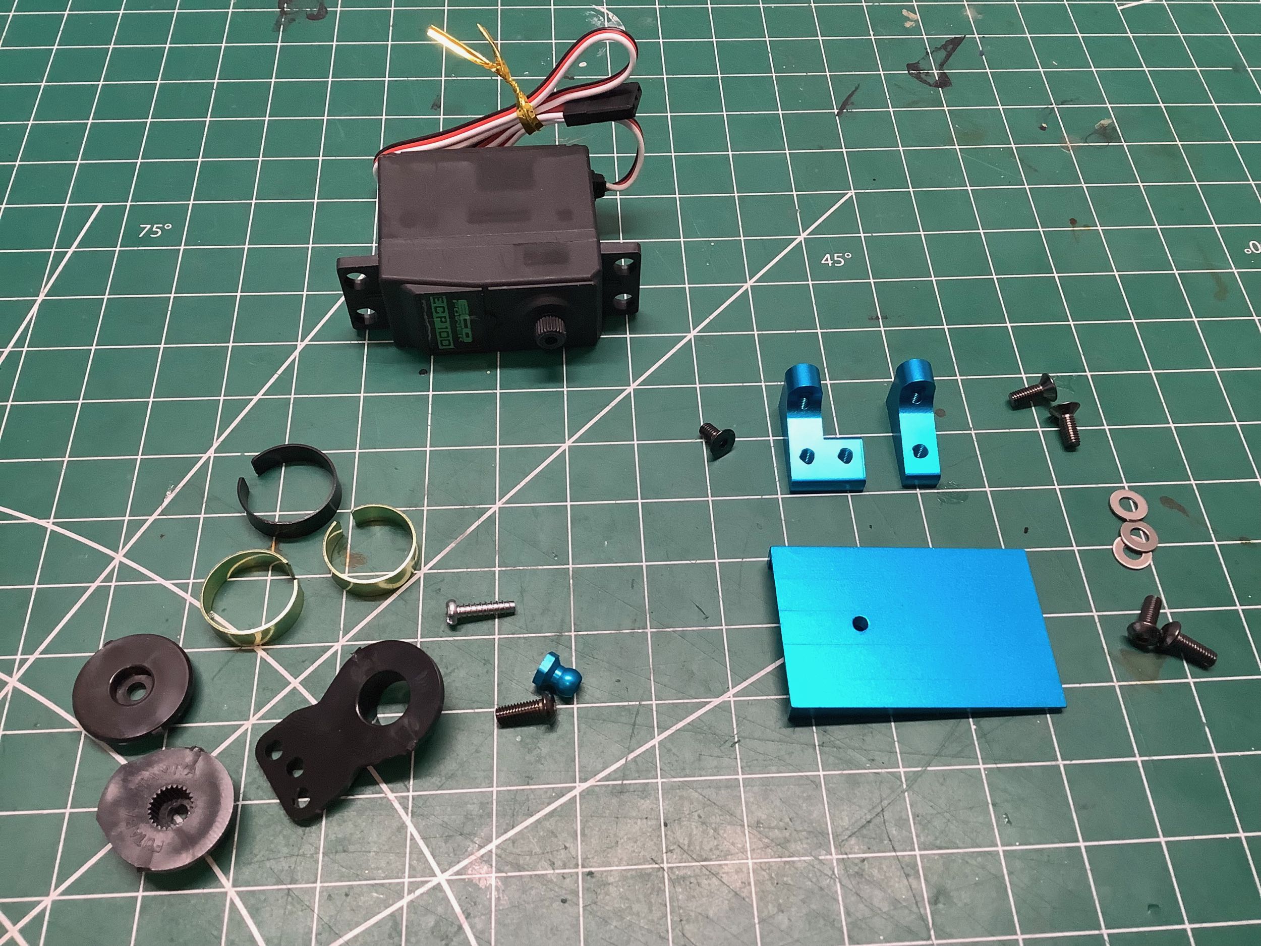
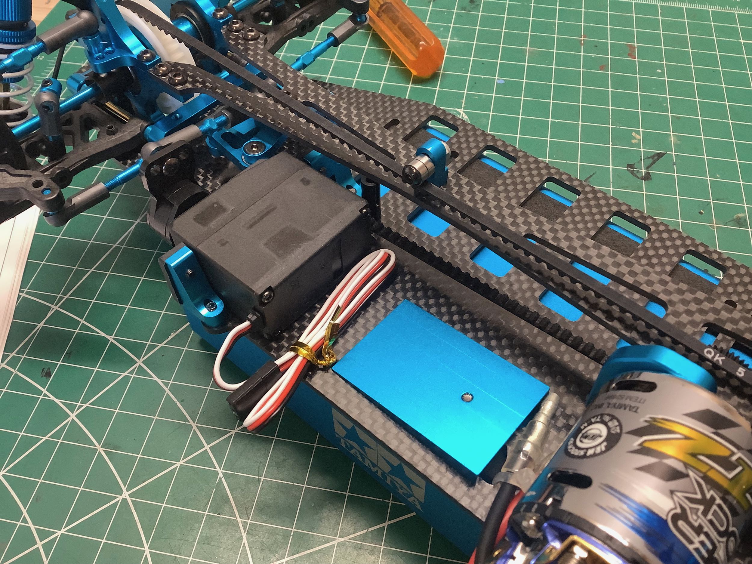
The TRF 416 is the first model I've built which includes slots in the
chassis for a ram induction scoop to cool the motor. The TRF
415MSXX had one, but I never built that model. I've also installed
a cheap servo at this point to hold the steering in place.
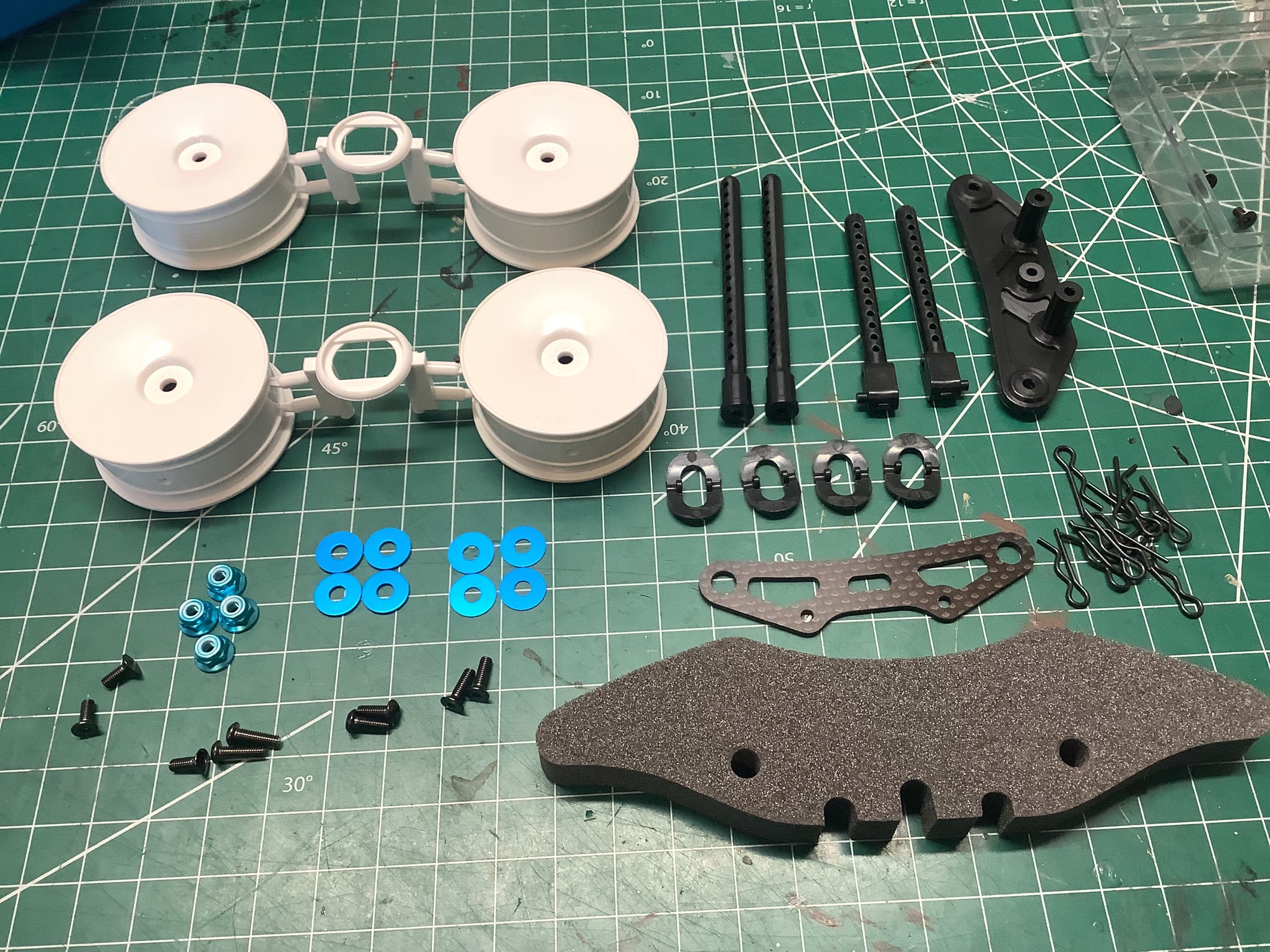
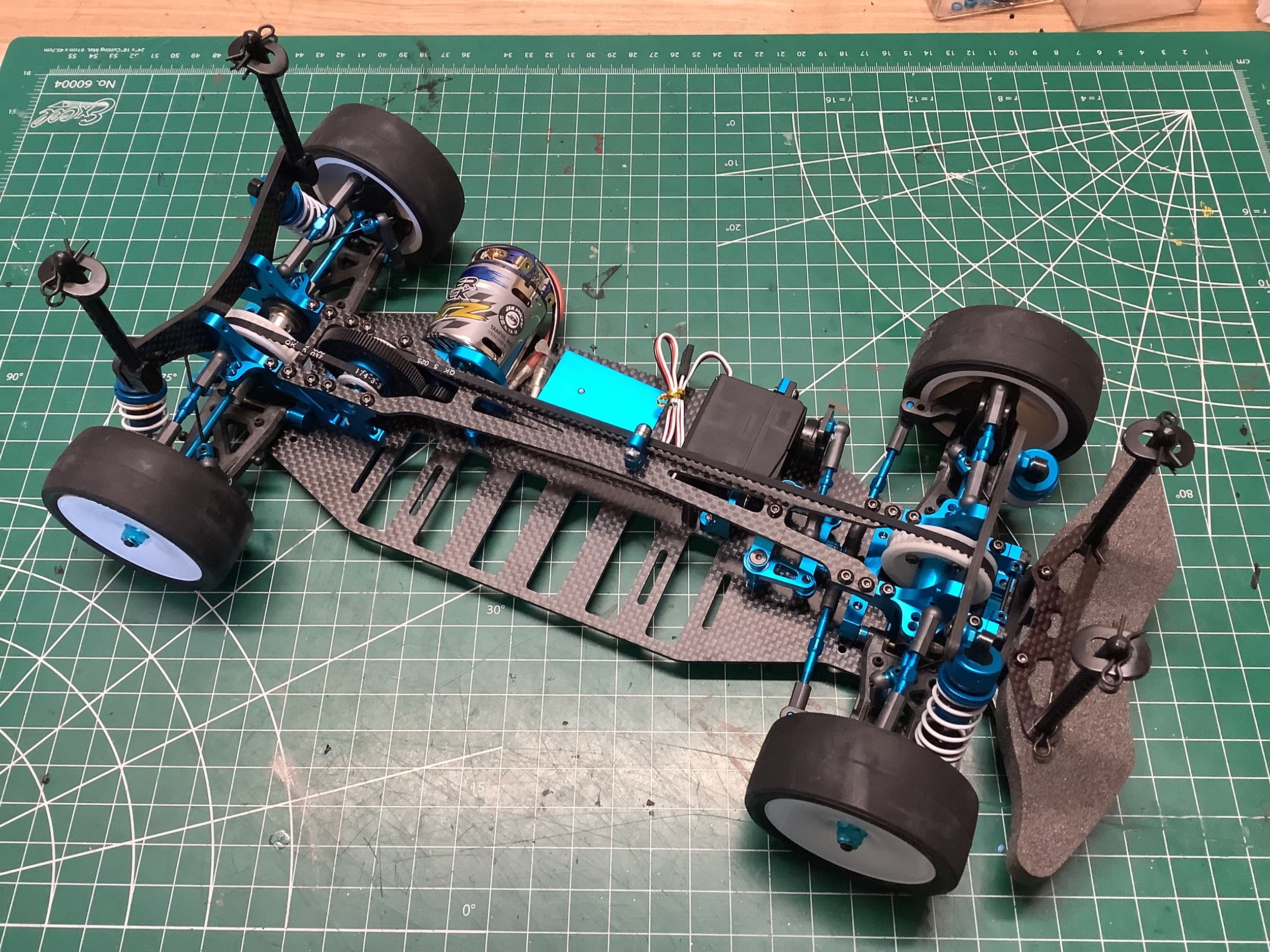
The TRF 416 did not come with any tires, but includes the same wheels
found in the TRF 415MSX. The bumper geometry has changed again and
a new carbon bumper support has been added. That completes the
chassis! It is quite lovely.
©2024 Eric Albrecht