Tamiya Lunchbox Mini Project
Page 1: Assembly
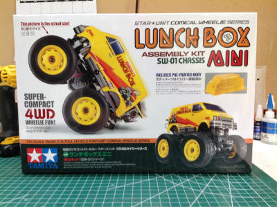
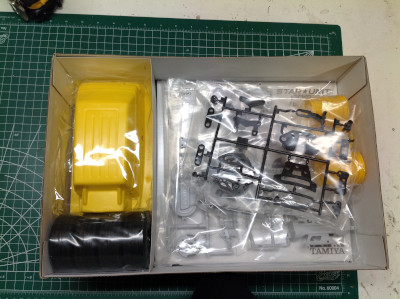
Considering the tiny size of the Lunchbox Mini, the box is pretty
big. You can see what a small portion of the space is consumed by
the body. There is ample empty space within the volume of the box.
The parts cover only a small portion of my build table, and there isn't
much hardware either. Still, the build ended up being more complex
than I expected.
The chassis parts are molded in very light gray while the gears are
black. The kit did not come with ball bearings, so the rubber
sealed bearings you see were supplied separately by me. In the
first step, a pair of spur gears are installed within the chassis
housing and enclosed.
The next set of gears installs from the outside of the chassis side and
is then hidden by a cover as shown. The larger end of the gears
are quite close together. The motor spur gear will span them and
drive both at the same time.
Here is the 370 sized brushed motor installed in its mount. The 16
tooth pinion gear is plastic and just presses onto the motor output
shaft. An 18 tooth gear can also be used for more top speed and
less torque, but this would come at the expense of wheelie
performance. On the right you can see the planetary style gear
differentials which come from the T3-01 and are identical front and
rear.
The outdrive axles have a dogbone at one end and a universal joint in
the middle which must be assembled manually. Unlike the T3-01, the
spline alone is not expected to carry the torque to the dogbone, there
is also a set screw inserted. On the right you can see the first
set of axles installed in the front uprights. The cotter pins are
only there temporarily to keep things together until the wheels are
installed.
The steering system on this vehicle is not like anything I've seen
before. The springs on the upper kingpins serve as the only
suspension. The bar which spans them pivots on the chassis tipping
the entire front axle back and forth. The steering therefore
results in body lean more like a motorcycle than a car. The
differential installs from the end of the chassis and is enclosed by a
cover as shown.
The front bumper and lower arms complete the front suspension, then the
rear is built in a very similar way. The only difference is that
the upper lever arm does not have a vertical slotted drive crank like
the front. Instead of a bumper, the rear of the chassis gets a
wheelie bar.
The steering just keeps getting stranger. The crank mechanism
shown serves both to turn the steering knuckles and to lean the
suspension at the same time. From bottom to top, the lower bronze
ball joints drive the steering arms, the screws above them support the
lower lateral link, the screws above those are the fixed structural
pivots, and the screws at the top support the upper lateral link.
One of the structural pivots is driven by a crank which will later
attach to the steering servo.
This view from above is intended to help with understanding of the
steering system, but probably doesn't. You really need to see it
in motion for it to make sense, and even then it is strange. Note
that the rear axle uses links which fix to the chassis so that the rear
doesn't steer. This can be changed with upgrade parts.
The electronics are all installed on their own upper bracket
assembly. Shown on the left is the installation of the steering
servo. The slot behind it is intended for a 4-AA battery box which
only comes with the Japanese version of the kit or a Lithium-Iron
battery which is likewise Japanese only. I'll be using a small 2s
LiPo. I stuck a small ESC to the top of the servo and the receiver
atop the battery box.
Now the electronics assembly can be bolted to the top of the
chassis. To mechanically connect it to the chassis only a small
steering tie rod is needed. To electrically connect it, you just
need to plug in the motor wires. Now the body can be
started. The yellow body comes painted but mostly uncut.
Only the wheel arches have been pre-trimmed. The picture on the
right shows the result after I've completely cut out the body.
Note that there are no clear windows.
The stickers must be painstakingly cut out and applied. In
addition to being small, they are also quite intricate. For
example, the stickers which must bend around the front bumper and
headlights have several triangular notches which allow them to cover
properly as shown. The completed body is shown on the right.
The windows are just stickers. The plastic parts on the lower
sides serve to simulate the side pipes of the bigger Lunchbox as well as
support the body on the chassis.
©2019 Eric Albrecht

