Tamiya Mini Cooper Rally Project
Page 1: Assembly
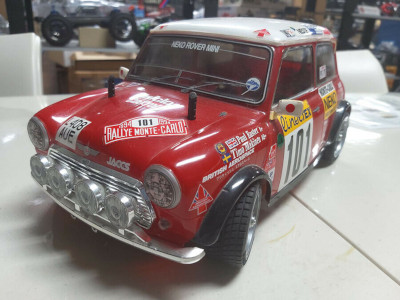
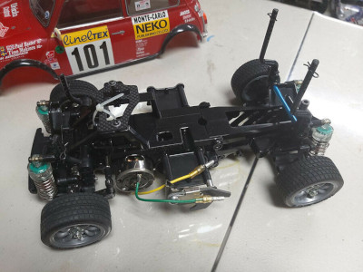
Here are a couple of pictures which were part of the eBay posting from
which I purchased the model. I chose it primarily because the body
and stickers looked to be in very good condition. The M-03
chassis on which it was mounted was sold to recover some of the money
spent on the auction, and it turned out to have a pretty long list of
upgrades which increased its value (though not its selling price).
I kept the wheels and tires. The wheels are the right style for
the Mini Rally, but they should really be chrome. I may replace
them some day.
The M-05 Version II R never came as a complete model, it was only
available as a chassis kit with no body, electronics, wheels, or
tires. That makes the box pretty small, but the contents are not
simple. In general M chassis are not very complex, but this one
appears to have a lot more going on that most.
This picture shows the metal parts of Bag A of the kit that I was able
to quickly find. All of the aluminum parts are black anodized
rather than the standard Tamiya blue. We have an aluminum motor
mount, servo mount, battery holders, lightweight hollow gear shafts, and
full ball bearings.
The first step involves preparing the chassis halves. While most
chassis either have a continuous tub, base plate, or are split along the
length, this chassis is split in half side to side. The gearbox
will be located between the sides. The aluminum motor mount is
attached to one side. The aluminum battery holders stick out the
sides to support a transverse mounted battery which apparently must be
secured with "glass fiber tape", something I'd never heard of
before. That's way too much hassle for me, so I reverted to the
regular plastic battery mounts.
The kit comes with reinforced gears which I'm pretty such just means
there is glass fiber in the plastic. The big gear holds the metal
bevel gears for the differential. This is not a sealed diff, but
it does use Tamiya's super thick Anti-Wear grease to give it a
reasonable amount of resistance to slip.
These photos show how the gears fit between the chassis halves.
This makes for a nicely protected gear mesh, but also means that it is
very difficult to access the gears if any maintenance is required.
The big gap in the back might look like it is for the battery, but
actually the electronics will fit under those beams. The battery
sits forward of that to move more weight over the front wheels.
Here are the metal parts for Bag B. Among them are some high
strength, low friction king pins (step screws), some aluminum steering
supports , some stainless hinge pins, and some very nice double cardan
axles. These can support a much larger driven turning angle than
dog bones or standard universals. They are fun to build as well.
Here the front suspension is being built and installed. It is very
compact because of the short arms. The 1-piece lower arms are
upgrades as are the uprights which are from the M-05 Ra, the rally
version of the chassis. There is no camber adjustment, but the
ride height can be changed by using an alternate set of holes on the
uprights. This model is being built in the lowest configuration.
Now the dual bellcrank steering has been completed. I found it a
bit strange that the little crank support brackets are aluminum but the
cranks and bridge are plastic. Seems backwards. There are
ball bearings in the cranks though, so the motion is quite nice.
The pinion gear mesh is not manually adjustable, instead there are 3
sets of holes to mount the motor which allow a 16, 18, or 20 tooth
pinion gear. The kit comes with the 20 tooth gear which should
provide the highest top speed. Because the motor is mounted inside
the chassis, the weight is pretty well centered which makes for good
lateral balance. The steering servo actually installs in the
back. Although this model is capable of accepting a regular sized
servo, it is really made to work best with a low profile servo so that's
what I got.
The kit comes with very nice copper colored TRF (Tamiya Racing Factory)
shocks. Of all the upgrades included in the "R" version of the
chassis, these are the biggest deal. The bodies all full machined
aluminum and the shafts are titanium coated. Piston heads and rod
support rings are Delrin. The right hand picture shows how many
parts it takes to make a single shock.
Now the shocks have been installed on the front and rear
suspension. All 4 are built the same. They are very short
and don't have much travel, but that's OK for a touring car
chassis. Note that the rear upper links are adjustable to rear
camber can be changed.
Going back a step, this picture shows the wheelbase adjustment of the
M-05 chassis. While most M-chassis change the wheelbase with
chassis plugs, this one is more subtle. There are multiple sets of
holes on the rear of the chassis. Depending on which holes you
use for the shock tower, on which side of the shock tower you install
the upper links, which holes you use for the lower arm support, and
which way around you install the support and arms, you can end up with a
short (210mm), medium (225mm), or long (239mm) wheelbase. The
entire rear axle moves to accommodate this variability which also means
you need various rear body mounts to get the body to align with the axle
position. I'm using the short wheelbase.
Now I can install the wheels, tires, and electronics. You can see
the very long steering link which is needed since the steering servo is
located all the way in the back. The ESC, servo, and receiver all
sit side by side across the back.
Finally, the prepared body can be dropped onto the chassis. The
body post locations made for a good alignment with the axles, but there
was a bit of interference at the front and rear bumpers. I had to
do a tiny bit of body trimming to make it fit perfectly.
Update 1:
After a while I decided that a standard silver can motor was not
sufficiently special for a chassis of this excellence. On the
other hand, I didn't really need the car to go any faster either.
To balance these two requirements, I selected a 28T Lightly Tuned motor
from Tamiya. This leaves the speed approximately the same but
makes me feel better.
Update 2:
These pictures show my updated model after the rebuild. The servo
and speed controller are different, and I also decided to use the
aluminum battery mounts this time so I could use a lithium battery.
©2019/2023 Eric Albrecht

