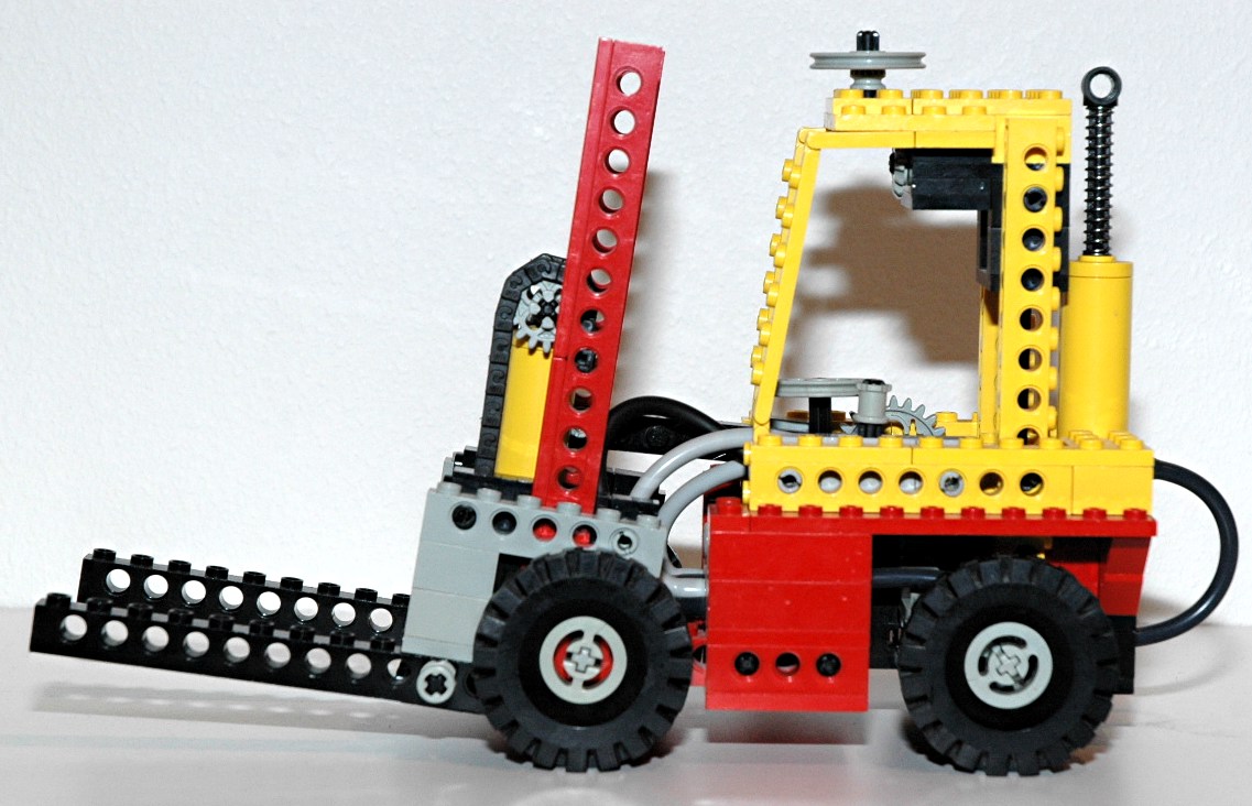
Features
|
|
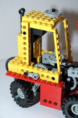
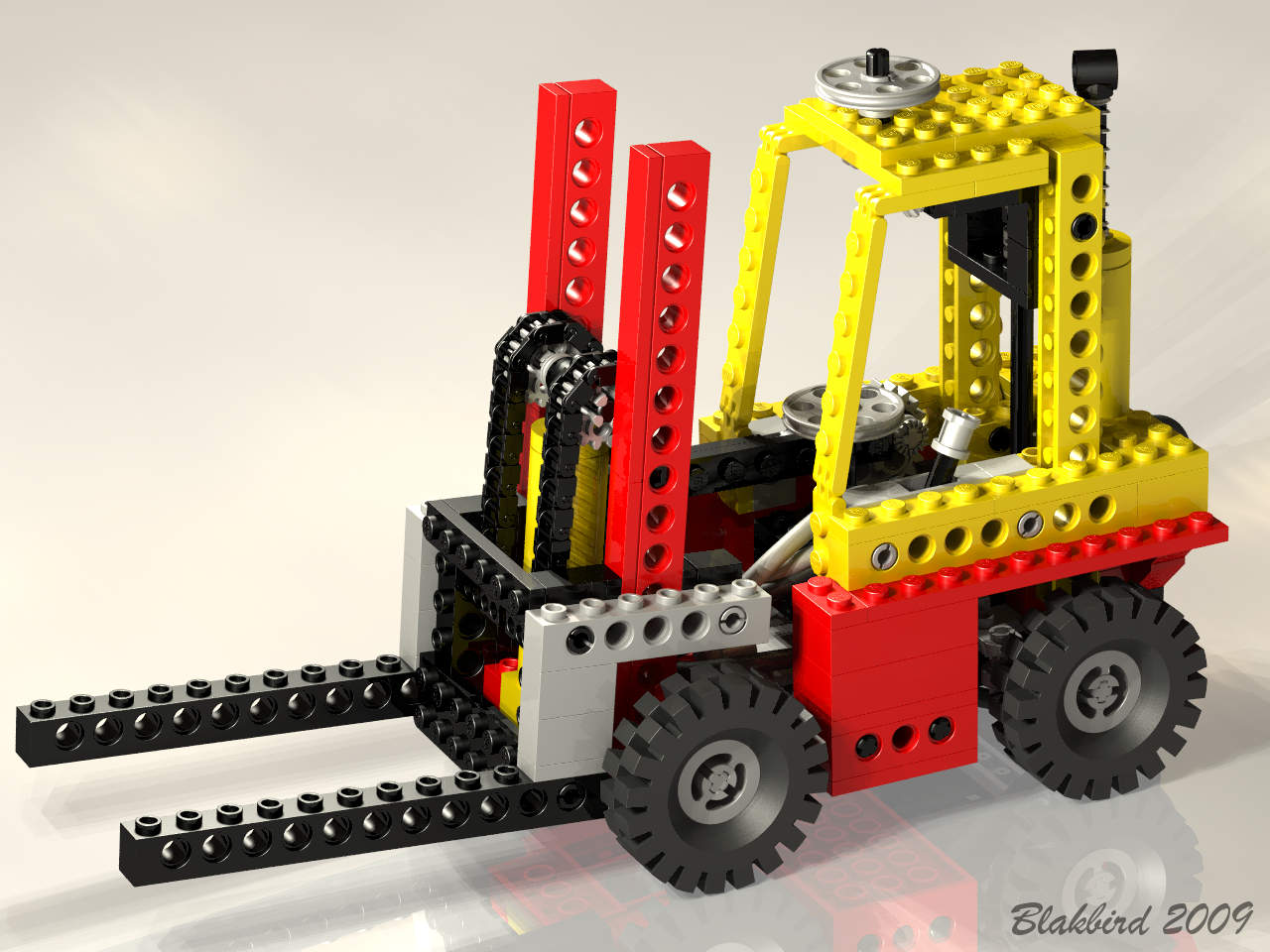
Steering
The rear wheels can be steered using an overhead control or a steering
wheel in the cabin. This is the first Technic model to combine
both steering inputs. (The
8846 Tow Truck had a backdriving steering
wheel but it could not actually be used to steer the vehicle because
the belt would slip.)
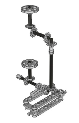
The path from the overhead control to the wheels is quite convoluted to
hide the axles. The overhead control drives an axle connected to
a pair of 14 tooth bevel gears. The second axle drives
another set which runs vertically down the aft of the cabin.
A third set of bevel gears drives a rack via a pair of 8 tooth pinion
gears. The steering mechanism itself uses the new control arms
and toothed links as shown in the computer image.
On the other side of the steering rack, on the same axle as the pinion
gears, another pair of 14 tooth bevel gears drive the steering wheel in
the cabin.
|
Click for an animation of the
steering in motion.
|
|
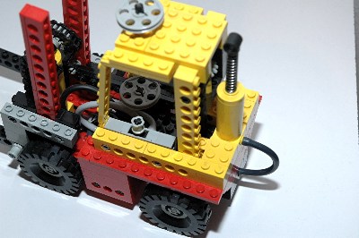
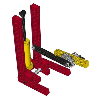
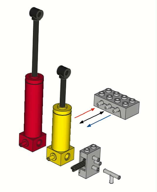
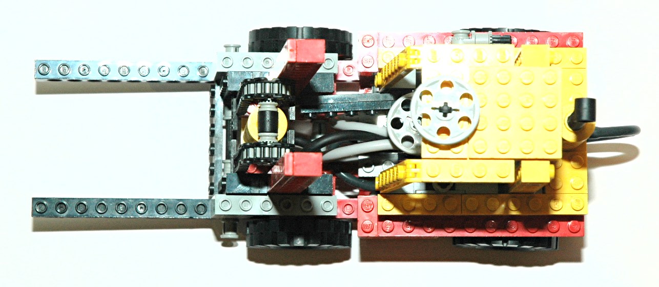
Pneumatics
This model contains a single acting pneumatic system. The components of
this system are connected with rubber tubing routed through the holes
in the beams.
A single pump provides air pressure. Depression of the piston
produces positive pressure, and raising the piston produces negative
pressure (suction), limited by atmospheric pressure.
The pressure is fed to a distribution block with an input (pump) and
two outputs (switch). One output has a check valve which flows
out and the other a check valve which flows in. Each of these is
routed to a different inlet of a selector valve (switch) with one
output. Selection of the switch in one direction therefore allows
pressure output, while selection in the other direction allows suction.
Finally, there is a pneumatic actuator which has a port at the head end
to accept input from the switch. Positive pressure extends the
piston, while suction retracts it.
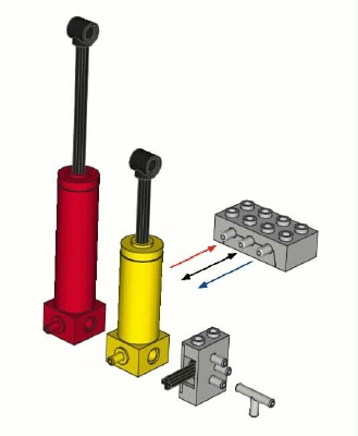
This model has the long stroke (64mm) pneumatic actuator which is only
found in two models.
In the picture, the actuator is on the left, the selector valve is in
the middle, and the pump is on the right. The distribution block
is not visible.
|
|
|
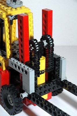
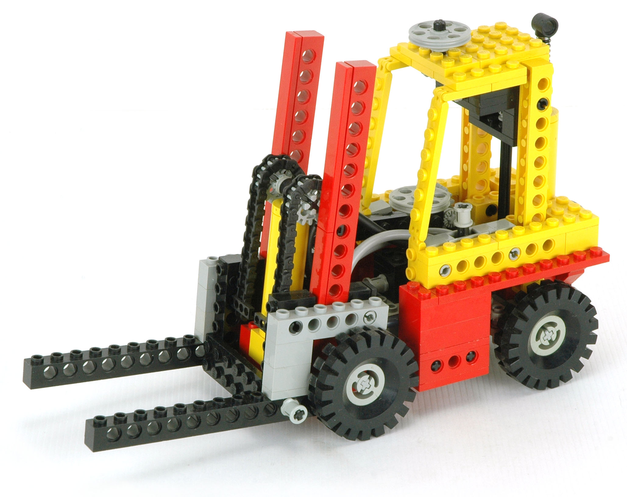
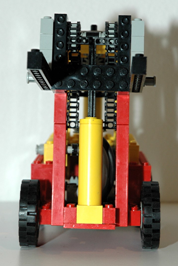
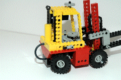
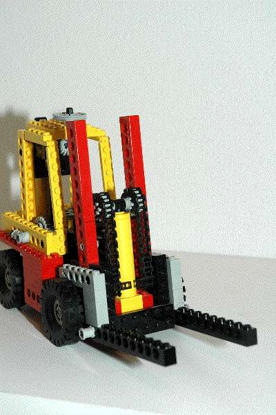
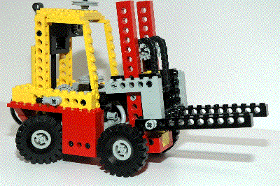
Forks
The forks can be raised and lowered using a pneumatic actuator.
The actuator does not drive the forks directly, but drives a pair of
chains via two 16 tooth gears used as pulley wheels. One end of
the chains is fixed to the vertical structure via a long chain link
(track), while the other end is attached to the moving forks (see
picture). Since the chain doubles back on itself, the chain has
to move twice as far as the pulleys to which it is attached. The
effect of this (a reverse pulley system) is that the forks can raise
and lower twice the distance of the stroke of the actuator.
When retracting, the actuator does not really pull the forks down, it
only lowers the pulley, removing the force which holds the forks
up. The forks must descend under their own weight, which works as
long as there is no binding in the system.
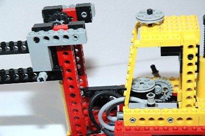
The moment created by the cantilevered weight is
reacted by a force couple: the upper forward load is reacted by a
set of tiles on the back of the vertical structural assembly, and the
lower aft load is reacted by contact of the
lower tiles against the vertical structural assembly. This use of
tiles on both sides makes the motion of this forklift quite smooth,
among the best of all the Technic forklifts.
|
Click for an animation of the forks
lifting.
|
|
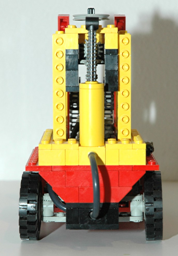
Fork Tilting
The entire fork and lift assembly can also be tipped forward to aid in
picking up a pallet from the ground (or dumping one on someone's
head). A lever on the right side made of a toothed connector
turns a 24 tooth gear used as a crank. A series of linear links
attached to the crank connect to the vertical structural assembly which
pivots about an axle on its base.
|
Click for an animation of the forks
tilting.
|
|
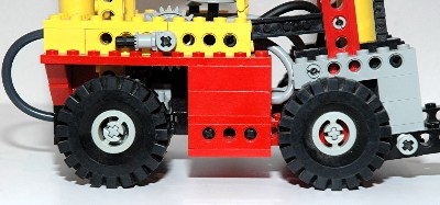
Wheels and Tires
This set uses four rubber 17x43 tires and standard old gray wheels.
|
|


