Features
|
|
Directional
Control
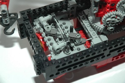
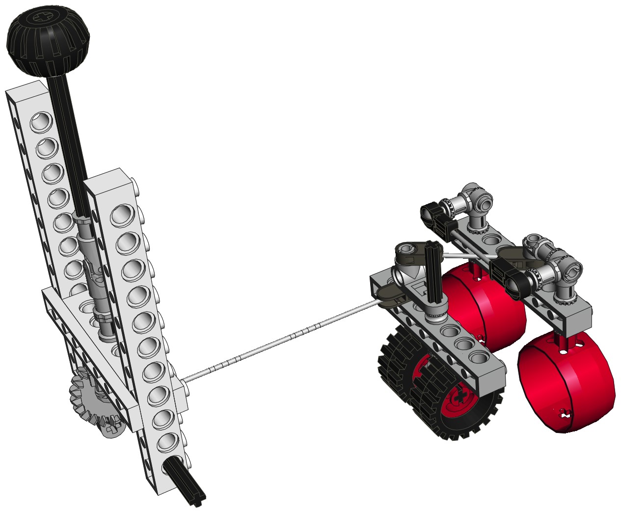
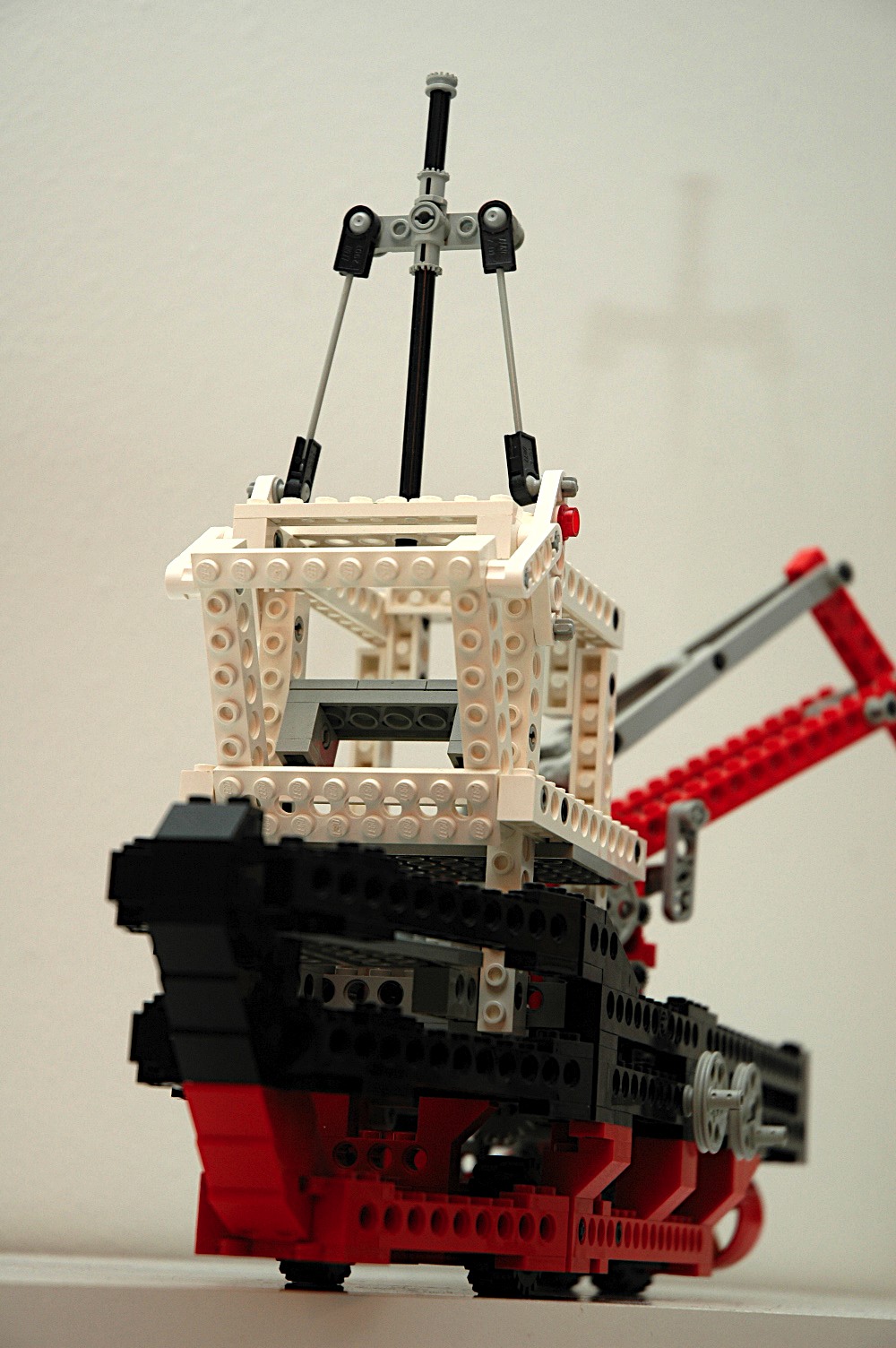
The ship has multiple means of direction control: one real and one
simulated.
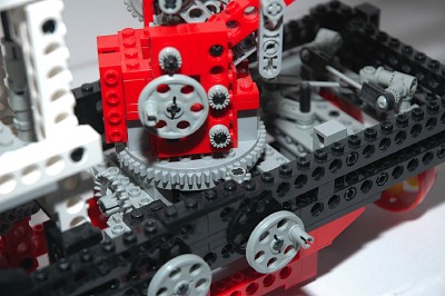
The simulated system is based on thrust vectoring. An overhead
"Hand of God" wheel drives a pinion gear meshing with a 24 tooth crown
gear. On this second axle is a liftarm used as a crank which
drives a flex cable. This flex cable runs aft to the steering
assembly. It drives an inverted steering arm used as a
crank. The opposite pin of the steering arm is used for
another flex cable. This cable is attached to a ball joint on one
of the propeller housing axes. Yet another flex cable attaches
the housings on the port and starboard sides. Movement of the
cables causes both housings to pivot together. Like you would
expect with this type of steering, the rotation of the housings is
opposite in direction to the turning direction of the ship. Note
that the propellers themselves do not pivot.
The real steering system is based on the fact that this model has 3
wheels hidden inside the hull. The two in the front are not
steerable, but the real wheel bogey can pivot. The same steering
arm which was mentioned above for use with the flex cables also turns
the steering axle. In this way, movement of the steering input
moves the prop housings and also turns the wheels to make the ship
really turn on solid ground.
|

Click for an animation of the
steering linkage in motion.
Click for an animation of the
thrust vectoring in motion.
|
|
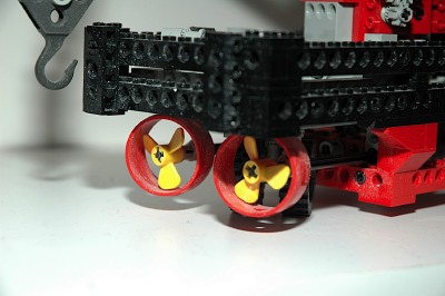
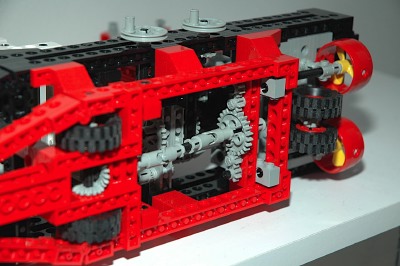
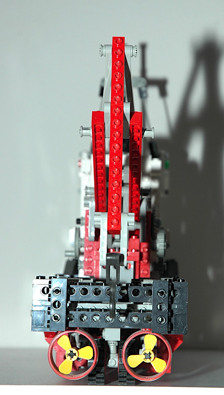
Propellers
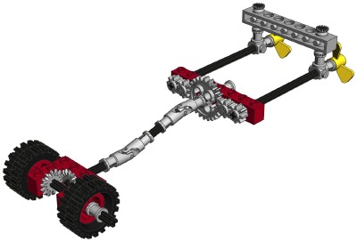
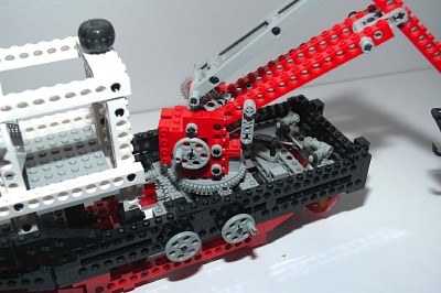
The hidden front wheels share an axle which drives through a pair of 14
tooth bevel gears. After passing through a pair of universal
joints, torque is transmitted to a 24 tooth spur gear. There are
2-8 tooth pinions on either side as can be seen in the computer
image. The final outboard gears turn drive shafts which rotate
the twin 3-blade propellers.
There's no differential thrust here; both props always rotate at the
same speed.
|
 |
|
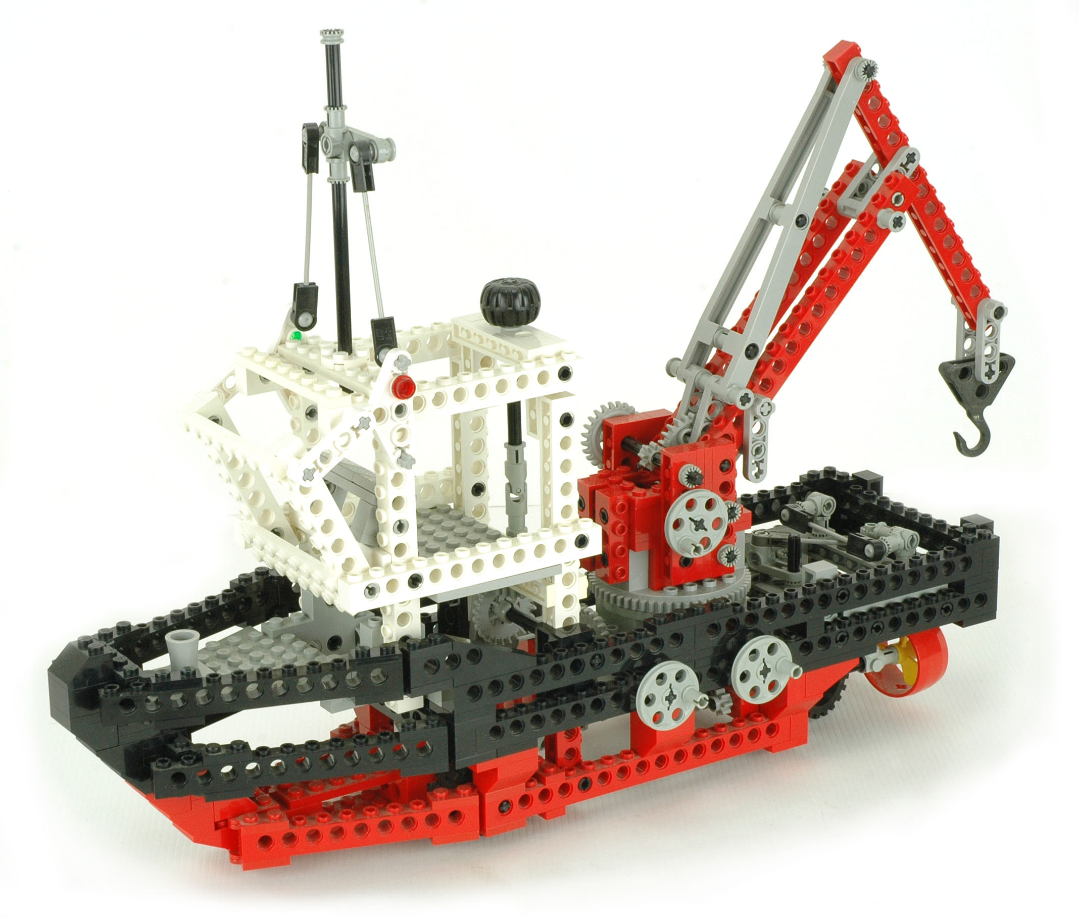
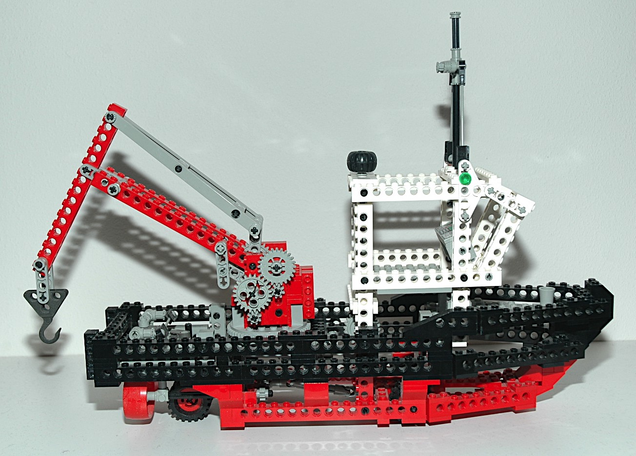
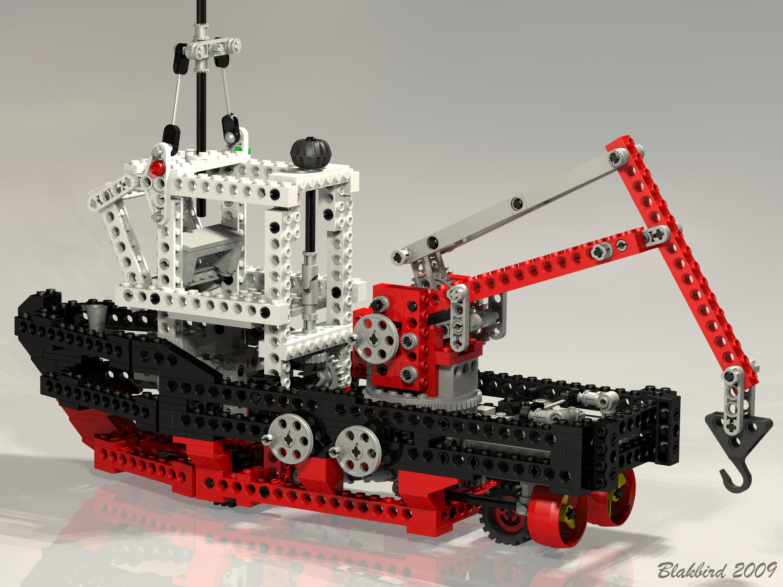
Slewing Crane
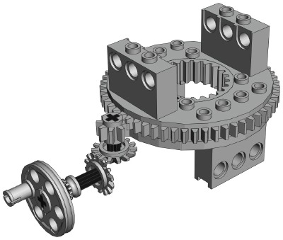
The loading crane is mounted to a turntable. A crank on the port
side turns a pair of 14 tooth bevel gears. An 8 tooth pinion then
drives the outer ring gear of the turntable. The crane cannot turn 360
degrees because the bridge is in the way.
|
Click for an animation of the crane
slewing.
|
|
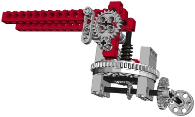
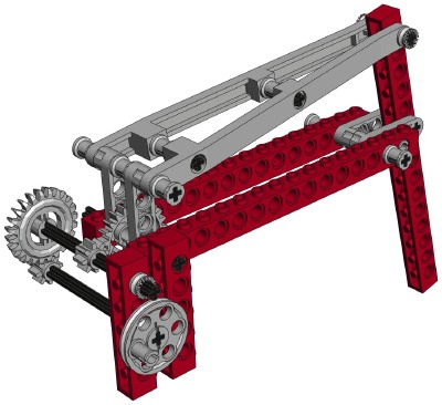
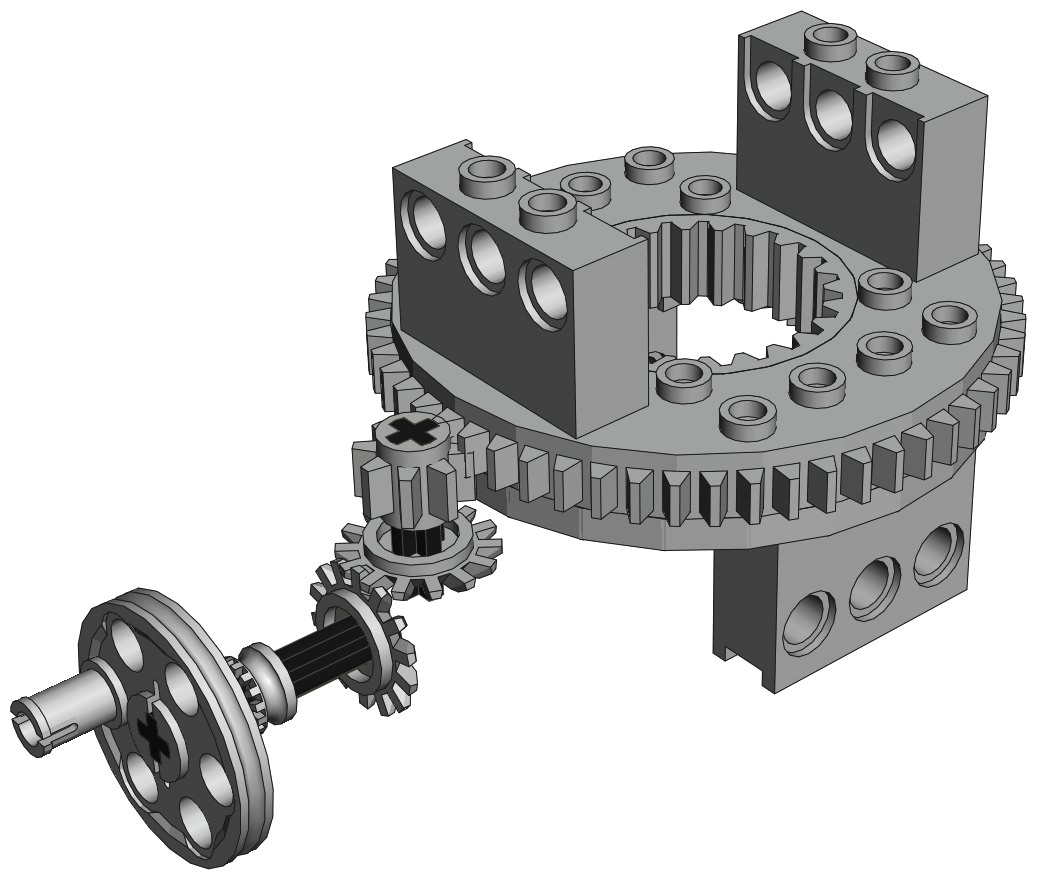
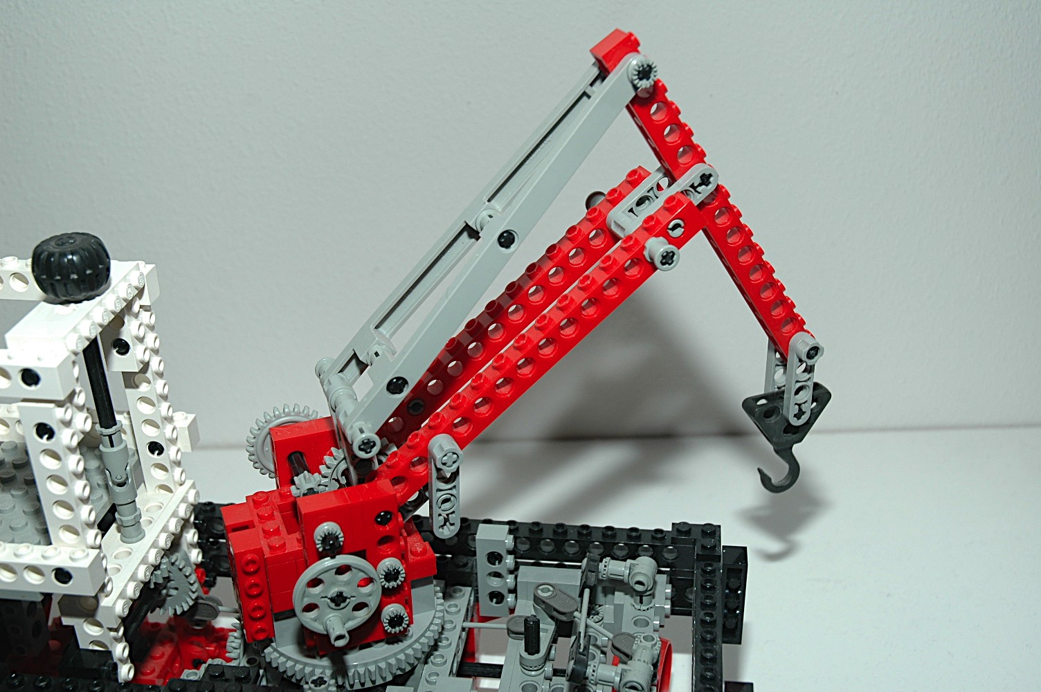
Luffing Boom
The main boom of the crane raises via a crank on the port side of the
hull. An 8 tooth pinion and a 24 tooth crown gear come
first. The a set of 14 tooth bevel gears pass torque up through
the center of the turntable to a worm screw. The worm screw
drives an 8 tooth which in turn drives another meshed with a 24 tooth
spur gear. This spur gear luffs the boom via liftarms which act
as a 4-bar linkage as seen in the computer image. Total gear
reduction is (24:8)*(14:14)*(8:1)*(24:8) = 48:1.
Use of a worm gear means that the system
cannot be backdriven because the axial friction is higher than the
backdriving torque due to the screw pitch angle.
|
Click for an animation of the boom in
motion.
|
|
Luffing Jib
The jib can be pivoted through a small angle through use of a crank on
the side on the crane base. Two sets of 8 and 24 tooth gears
result in a gear reduction of 9:1. The final gear turns a pair of
liftarms which have a moment arm of 3L. A pair of long tapered
arms then reach out to the jib. Since the jib has a moment arm of
5L, it does not rotate very far but has a large lifting capacity.
The jib liftarms have a hard stop at either end when they contact the
top of the crane housing.
|

Click for an animation of the jib in
motion.
|


