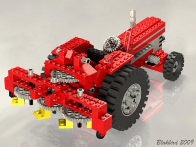
Features
|
|
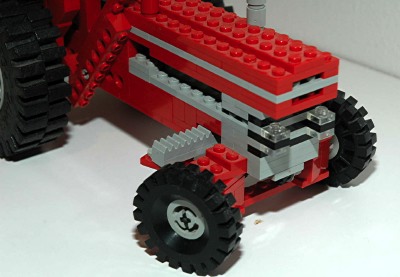
Steering
The front wheels can be steered using a wheel made from a 24
tooth gear at the driver's
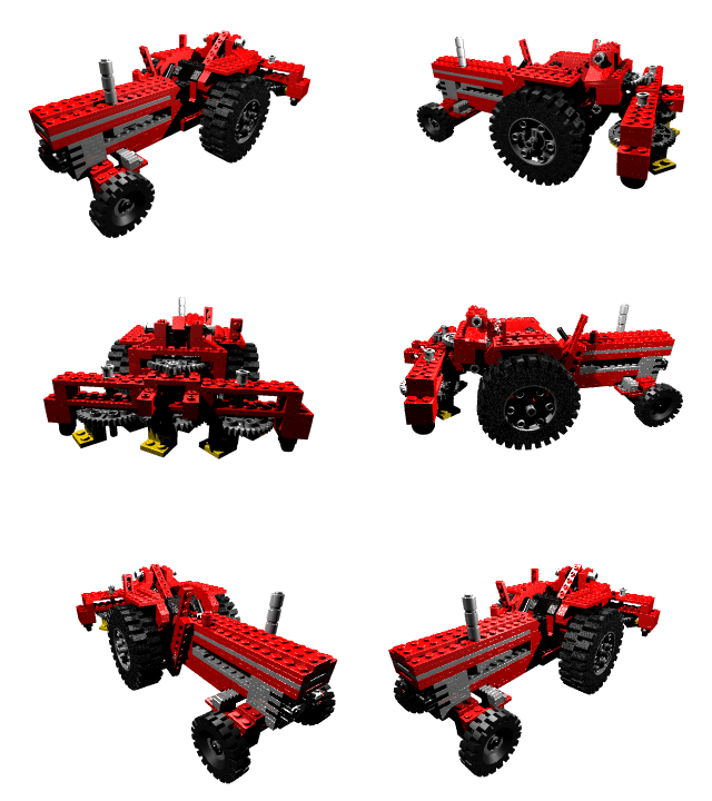
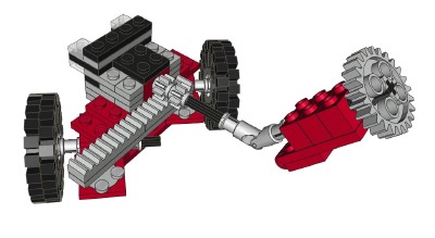
position. As can be seen in the computer generated image, the
wheel drives an axle connected to a pair of 8 tooth pinion gears via a
universal joint. The pinions
drive a pair of racks. The steering mechanism itself uses 6
traditional 2x2 swivels with 2 pair allowing rotation of the wheels
about the vertical axis and another pair acting as control arms
attached to the rack gears. Simple axles allow the wheels to
rotate freely.
|
Click for an animation of the
steering in motion.
|
|
Implements
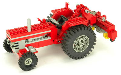
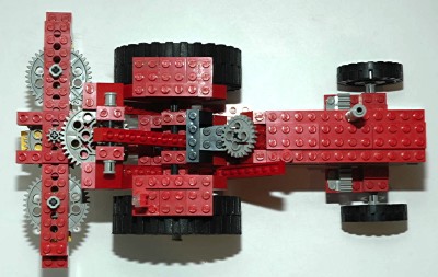
The right rear wheel of the tractor drives a PTO (Power Take Off) via a
bevel set using an 8 tooth pinion and a 24 tooth crown gear. This
gives the PTO a gear ratio of 3:1. The left rear wheel is not
connected to this mechanism.
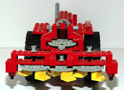
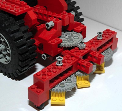
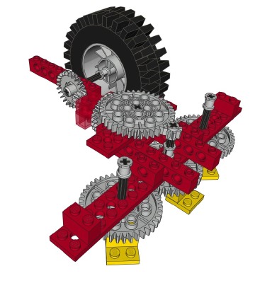
The implement for the primary model is a thresher. The PTO drives
a 40 tooth spur gear on the thresher which, in turn, drives an 8 tooth
spur gear. This final set of gear reduction drives a trio of 40
tooth gears acting as cutting wheels. Yellow bricks are inserted
into some of the stud holes in the gear to act as cutters.
The final gear reduction at the cutters is 9:1 with respect to the rear
wheels, so these turn very quickly when engaged (see animation).
They turn so quickly that this creates a lot of drag on the tire and
tends to make it slip.
|
Click for an animation of the thresher
in motion.
|
|
Lift
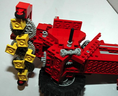
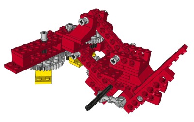
The thresher can be raised and lowered via a lever at the driver's
position on the right side. The lever pivots about the frame and
drives a push-pull link made from connectors. This link pushes a
four bar linkage which raises the implement, keeping it (almost)
parallel to the ground during motion. The reason it is not quite
parallel is that the vertical distance between the upper and lower
links is not equal at the front and the back, so the links are not
quite parallel.
As long as the model is right side up, the push-pull linkage is always
in compression so it tends to stay together. If the model is
inverted, this is in tension and can pop apart.
If the thresher is lowered too far, the 40 tooth gear will fall under
the PTO and jam. There are wheels on the thresher to make it
level and prevent this from happening.
The original mechanism (pictured) had a weak spot at the aft end of the
connector link. Only the friction on the studs kept this
together, so it tended to come apart often. In 1978, LEGO®
changed the design to have a vertical 1x4 beam at this location to hold
things together. This resulted in a slightly different parts list
and count for this set.
|
Click for an animation of the lift in
motion.
|
|
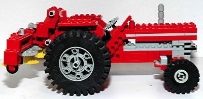
Wheels and Tires
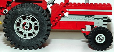
This set uses two rubber 17x43 tires and standard old gray wheels on
the front. The rear uses a foam 24x43 tire and wheel, the biggest
foam tire that LEGO® made.
|
|

