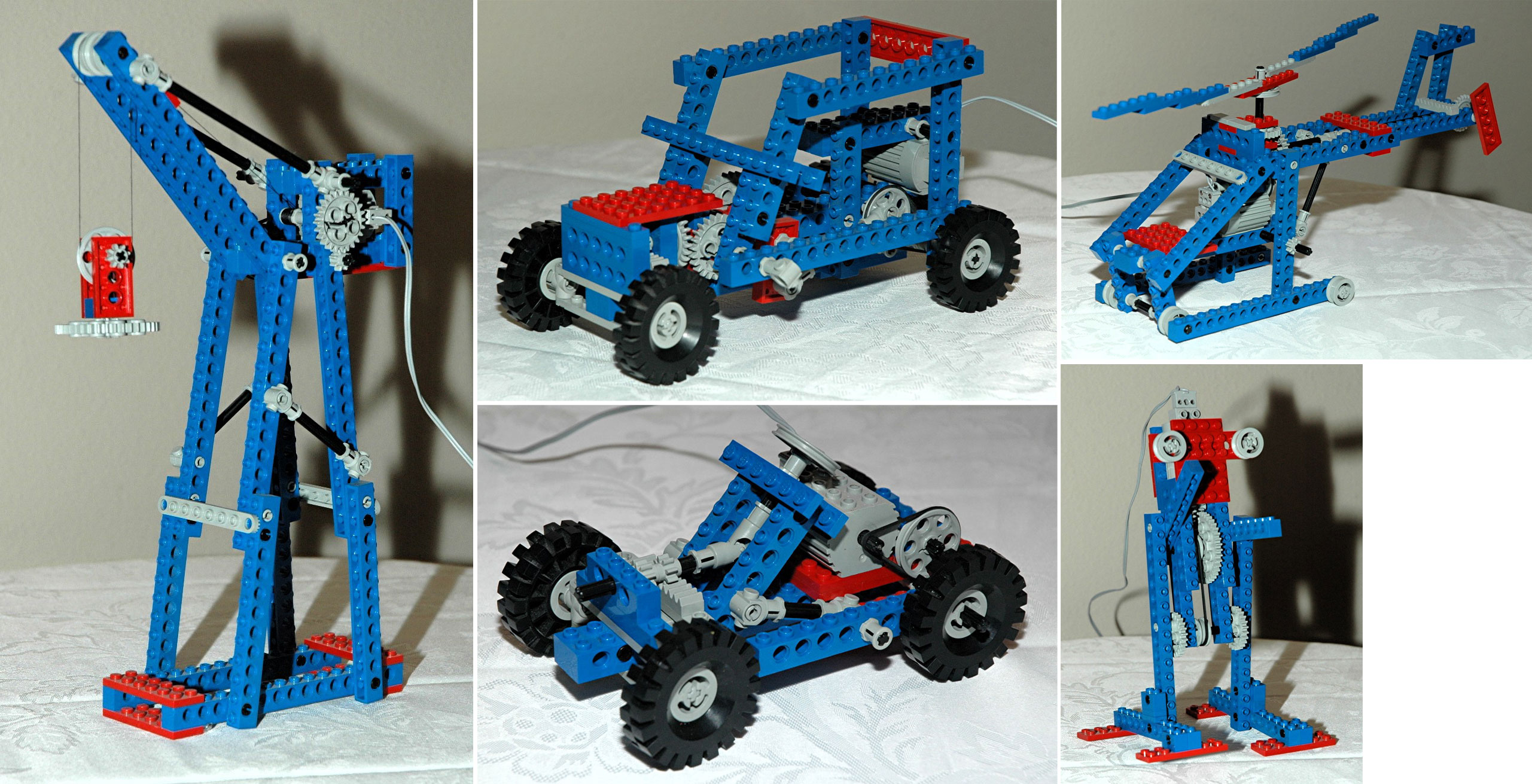
1st Model: Car
|
This
little car has manual steering and a motor driven rear axle.
The front wheels can be steered using a wheel in the cabin. The
wheel drives an 8 tooth pinion gear through a
universal joint. The pinion drives the steering rack. The
steering mechanism itself uses
control arms and toothed links.
The motor is mounted on the driver's seat and drives a pulley via a
belt which results in considerable gear reduction. The pulley
drives through a set of 8 and 24 tooth spur gears for yet another set
of
gear reduction. The 24 tooth gear is on the rear axle.
The rear axle helps hold the frame together and consequently carries a
bit of shear load which tends to make the axle bind.
|
 
Click for an animation of
the
steering in motion.
Click for an animation of
the car in motion.
|
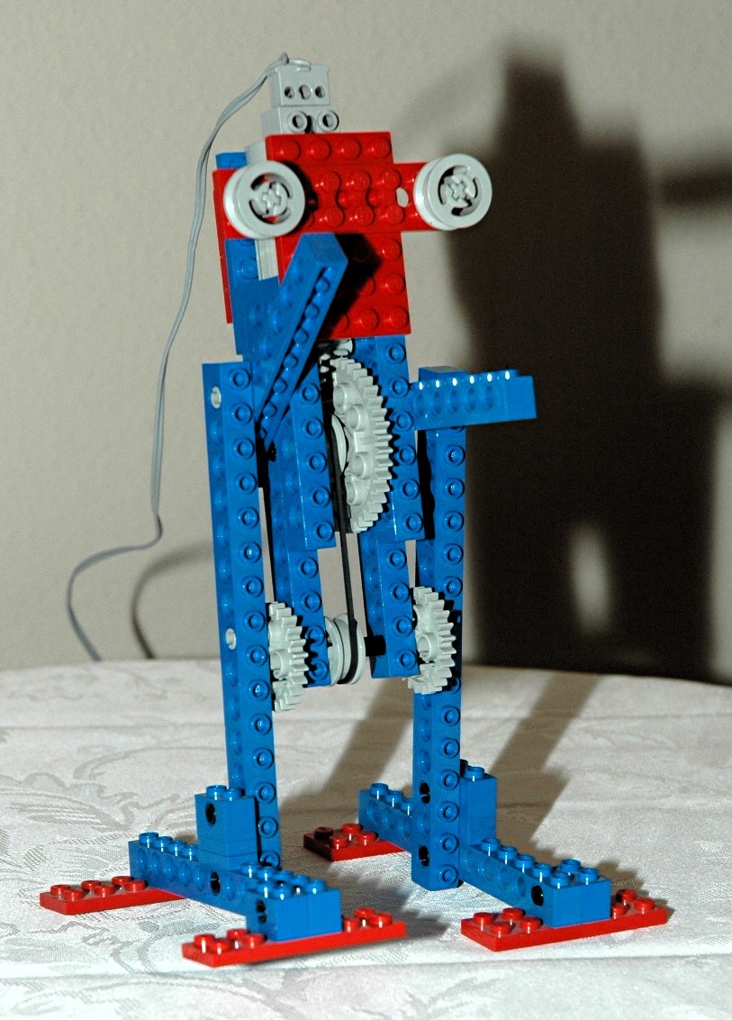
2nd
Model: Robot
|
LEGO®
gets big points from me for doing something other than a vehicle, but
this little robot isn't exactly Asimo. It "walks" in a manner of
speaking, but more realistically looks like it is having a seizure.
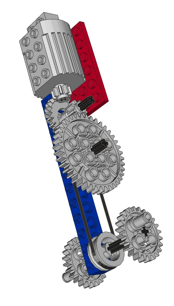
A motor mounted in the head of the robot has an 8 tooth pinion on the
output shaft which drives a 24 tooth crown gear. The next stage
is a set of 8 and 40 tooth spur gears which then drive a belt down to
the robot's "waist" where a pair of 24 tooth gears act as cranks using
the offset pin holes (see computer image). This final ratio of
15:1 sounds like a lot, but the legs still move way too fast to make
this guy stable. One of the Technic gear reduction boxes would do
wonders here, but would move the center of gravity even higher.
The top end of the "legs" attaches to the second hole of the "arms"
which makes them flail wildly while the robot attempts to "walk".
As you look at the animation, you can see that the motion is highly
nonlinear. First it moves very slowly, then it suddenly lurches
as the balance shifts to the next side.
|


Click for an animation of
the robot in motion.
|
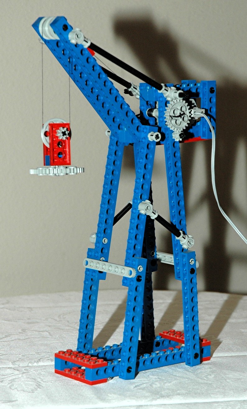
3rd
Model: Stationary Crane
|
This
free-standing stationary crane looks nice but doesn't do much.
A pair of trusses support a hoist system. The motor drives a
pulley via a belt, after which a set of 8 and 24 tooth gears turn a
cable drum. The cable then proceeds up the fixed boom and down to
a sheave. The sheave has its own pulley which further reduces the
motion 2:1 compared to the cable.
This system is hampered by the fact that the pulley axle (shown in red
in the computer image) also supports
the weight of the motor on the legs and therefore tends to bog down and
not turn
well.
|
|
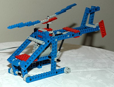
4th
Model: Helicopter
|
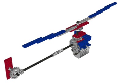
This
fairly large helicopter features rotating main and tail rotors.
The motor is mounted in the cockpit and drives a pulley via a
belt. Next, a set of 8 and 24 gears lead to an axle heading back
to the tail rotor. In parallel, a second 24 tooth spur gear is
actually used as a bevel gear. This is the only place I have seen
this done. Normally a crown gear would be used here, but the spur
gear was needed for other models in this set so it was all that was
available.
The rotors rotate well although the angular velocity of the main rotor
is far too fast with respect to the tail rotor (3:1). It should
be
the other way around.
|
Click for an animation of
the rotors in motion.
|
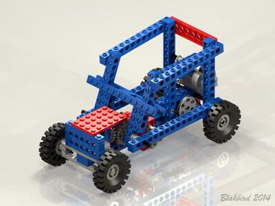
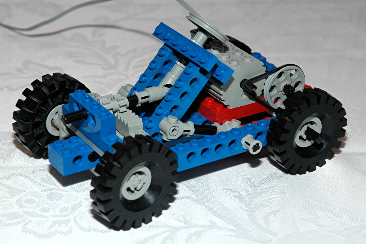
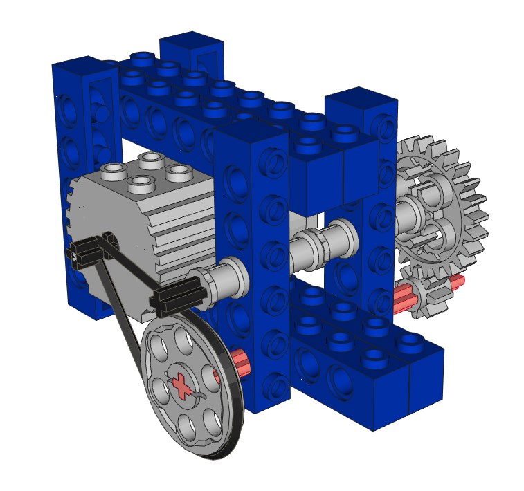
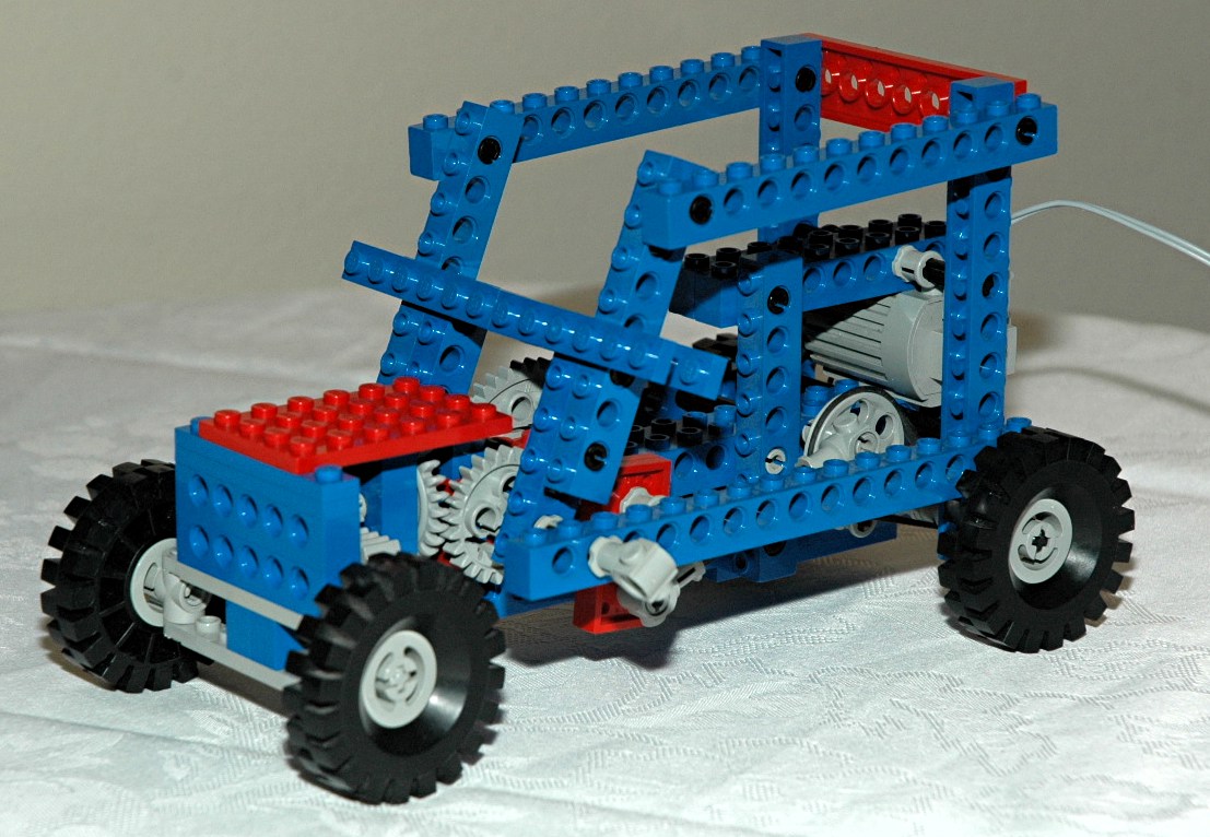
5th
Model: Buggy
|
This
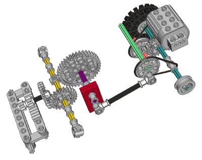
buggy has a unique mechanism which couples the motorized rotation of
the rear wheels to an oscillation of the front wheel steering.
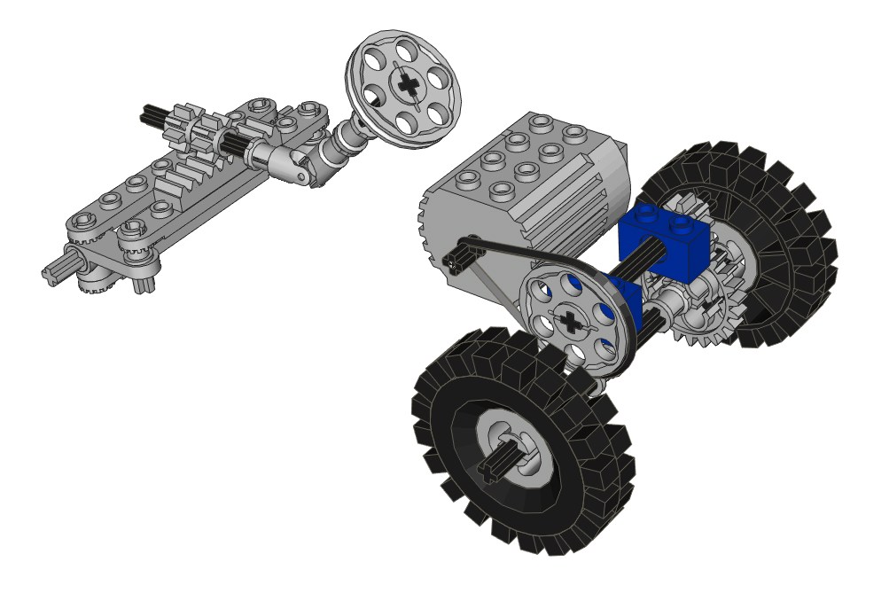
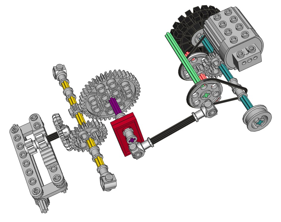
As can be seen in the color coded computer image, the motor belt
drives a pulley
(red axle) which, through a set of 8 and 24 tooth spur gears, drives
the rear
axle (blue). The rear axle drives another pulley (green axle)
through a belt. This pulley acts as a crank and drives a
pushrod. This pushrod turns a crank in the middle of the vehicle
(purple axle) which controls the rack and pinion steering through a set
of 40
and 8 tooth gears, followed by a pair of 24 tooth gears (yellow
axle). The
steering mechanism itself uses
control arms and toothed links.
It is very important that the correct gear tooth be chosen when rigging
this system or it will tend to steer more in one direction that the
other.
Because the steering is belt driven, it tends to slip much of the
time. Even when working, the model doesn't turn very well because
of the solid rear axle. Still, this is a great model to
demonstrate how a variety of functions can work.
|

Click to download the LDraw
file of this model.
Model by Eric Albrecht
Click for an animation of
the mechanism in motion.
|


