
| Original
Year |
1993 |
|---|---|
| # of
pieces |
225 |
| Categories |
Other: Universal Sets |
| Dimensions |
various |
| Models |
Car Forklift Cherry Picker Log Loader |
 |
|
||||||||||
8042 Pneumatic Universal Building Set
|
| 1st Model: Car |
|
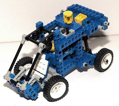
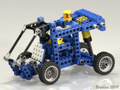
| This
little
car has front wheel steering and a pneumatic system which opens
the front canopy. The model itself is not particularly
noteworthy, but the use of a pneumatic pump as a shock absorber is
clever. This model does not use the small pneumatic cylinder. |
  Click to download the LDraw file of this model. Model by Benjamin Wendl |
|
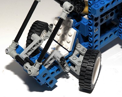
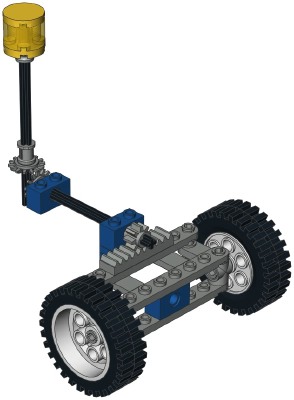
Steering
The front wheels can be steered using an overhead "hand of god"
wheel. The
wheel drives a set of 14 tooth bevel gears. The second axle
drives a pinion. The pinion drives the steering rack. The
steering mechanism itself uses
control arms and toothed links. |
  Click for an animation of the steering in motion. |
|
Pneumatic Canopy
The rear axle features a trailing arm type suspension. The axle
actually passes through the hole in the translating end of the pneumatic pump. This is one of the very few cases in which this
hole is actually used. The opposite end of the pump is pinned to
structure. The result is that the spring acts as a rear shock
absorber. Depression of the suspension builds pressure in the
system.A large pneumatic cylinder lifts the front canopy for access to the front seat. The pneumatic switch is located on the roof. |
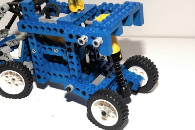 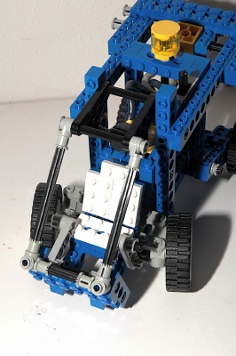 Click for an animation of the canopy in motion. |
| 2nd
Model: Forklift |
|
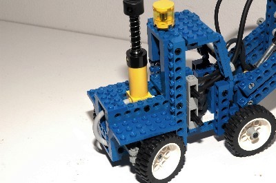
| There
have
been a lot of forklifts over the years so it is hard to make one
which stands out. I actually find the looks of this one quite
appealing. Functionally, the vertical lift capability is too
small to be useful for much and the model is very front heavy. The pneumatic pump is on the rear end. The switches are stacked on the right side and control the two pneumatic functions. |
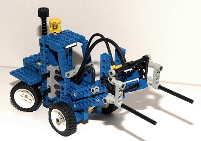
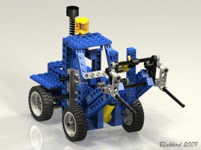 Click to download the LDraw file of this model. Model by Benjamin Wendl |
|
Steering
The rear wheels can be steered using an overhead "hand of god"
wheel. The
wheel drives a set of 14 tooth bevel gears. The second axle
drives a pinion. The pinion drives the steering rack. The
steering mechanism itself uses
control arms and toothed links. |
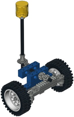 Click for an animation of the steering in motion. |
|
Pneumatic Lift
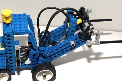
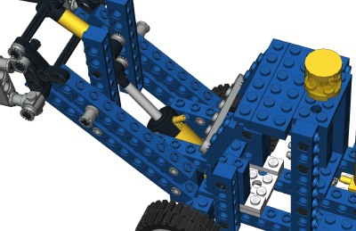
The forks can be lifted via a large pneumatic cylinder. A 4-bar
linkage keeps the forks parallel to the ground during lifting.Because of the way the cylinder is oriented, the total amount of lift height is small. The mechanism is capable of going higher, but the cylinder runs out of travel and bottoms in the extended position. |
  Click for an animation of the forks lifting. |
|
Pneumatic Tilt
A small pneumatic cylinder drives the tilt of the forks. The tilt
angle range is fairly scale compared with a real forklift.
However the small output capability of the cylinder, combined with the
already front heavy design of the vehicle, make the total lifting
capability small. |
 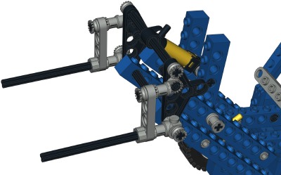 Click for an animation of the forks tilting. |
| 3rd
Model: Cherry Picker |
|
| I
like this unique model very much. It would be over a decade
before another cherry picker would be available. The model
steers, features rear outriggers, and raises the rear arm via a very
clever mechanism. The pneumatic pump is just behind the cabin and the switches are located on the right side of the frame. |
|
|
Steering
The front wheels can be steered using an overhead "hand of god"
wheel. The
wheel drives a set of 14 tooth bevel gears. The second axle
drives a pinion. The pinion drives the steering rack. The
steering mechanism itself uses
control arms and toothed links. |
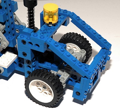
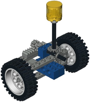 Click for an animation of the steering in motion. |
|
Pneumatic Lift
This lift is cool, and you may have to stare at it for a wheel to grasp
the kinematics. The animation should help.The main power comes from a large pneumatic cylinder which is pinned to the frame at the bottom. The lower set of links is a 4-bar linkage made from vertical beams at each end, a long beam at the bottom, and an axle with connectors at the top. Thankfully, the statics are such that the axle is always in compression so it does not pull apart. The upper set of links is a very similar 4 bar linkage. In this case, the final link is the cradle which remains level throughout lifting. The real magic comes in the interaction between these two linkages. The pneumatic actuator actually attaches to the upper set of links. The lower set just follows along for the ride and maintains parallelism. Therefore, none of the weight is actually supported by the lower set of links. An angled toothed link joins the upper and lower links. The angle of this link ensures that when the actuator is retracted, the system is properly stowed with everything parallel to the ground. |
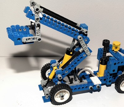 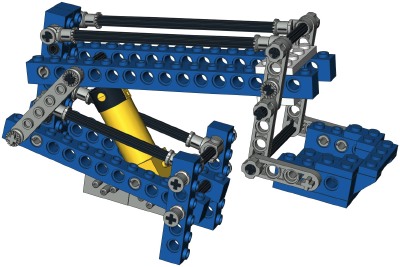 Click for an animation of the lift in motion. |
|
Pneumatic
Outriggers
A pair of outriggers on the rear bumper are driven by a small pneumatic
cylinder. Because their footprint is actually narrower than that
of the rear wheels, they do nothing whatever to stabilize the vehicle,
but they look cool. And in the end, isn't that all that really
matters? |
 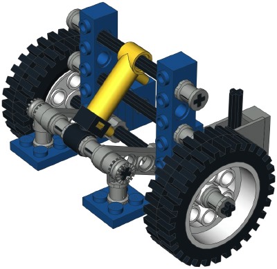 Click for an animation of the outriggers in motion. |
| 4th
Model: Log Loader |
|
| A
log loader is a rare Technic commodity. This one is a little
goofy looking but fairly functional. It features steering and two
pneumatic functions. The pneumatic pump is just behind the cabin and the switches are stacked on the left side of the frame. |
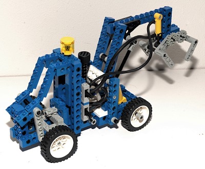
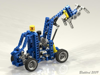 Click to download the LDraw file of this model. Model by Benjamin Wendl |
|
Steering
The front wheels can be steered using an overhead "hand of god"
wheel. The
wheel drives a set of 14 tooth bevel gears. The second axle
drives a pinion. The pinion drives the steering rack. The
steering mechanism itself uses
control arms and toothed links. |
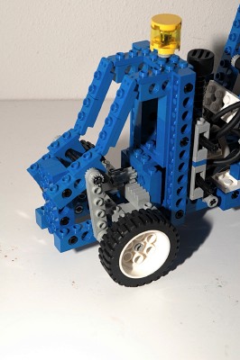
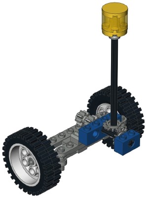 Click for an animation of the steering in motion. |
|
Pneumatic Boom
The rear main boom can be raised via a large pneumatic cylinder.
The lift mechanism is just a simple cantilevered beam. The jib angle actually changes slightly during lift. This is due to the fact that the two vertical arms of the 4-bar linkage are different lengths. You can see this angle change in the animation. The animation also shows the retraction force of the actuator is enough to lift the back of the vehicle off of the ground. |
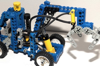 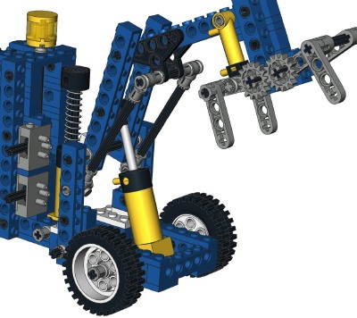 Click for an animation of the boom in motion. |
|
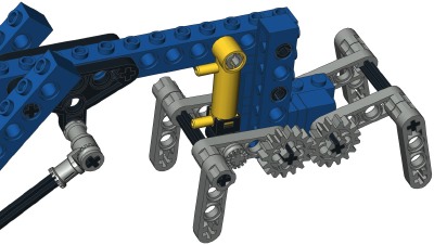
Pneumatic Claw
A claw on the end of the jib can be opened and closed via a small
pneumatic cylinder. The two sets of teeth are linked together via
a set of spur gears which keeps them synchronized and drives them in
opposite directions. |
  Click for an animation of the claw in motion. |